EP4391236A1 - Ensemble de raccordement - Google Patents
Ensemble de raccordement Download PDFInfo
- Publication number
- EP4391236A1 EP4391236A1 EP23214146.5A EP23214146A EP4391236A1 EP 4391236 A1 EP4391236 A1 EP 4391236A1 EP 23214146 A EP23214146 A EP 23214146A EP 4391236 A1 EP4391236 A1 EP 4391236A1
- Authority
- EP
- European Patent Office
- Prior art keywords
- clamping
- slide
- conductor
- arrangement
- holding
- Prior art date
- Legal status (The legal status is an assumption and is not a legal conclusion. Google has not performed a legal analysis and makes no representation as to the accuracy of the status listed.)
- Pending
Links
- 239000004020 conductor Substances 0.000 claims abstract description 99
- 230000008878 coupling Effects 0.000 claims description 9
- 238000010168 coupling process Methods 0.000 claims description 9
- 238000005859 coupling reaction Methods 0.000 claims description 9
- 238000003780 insertion Methods 0.000 description 16
- 230000037431 insertion Effects 0.000 description 16
- 239000000463 material Substances 0.000 description 3
- 239000007769 metal material Substances 0.000 description 3
- 238000011161 development Methods 0.000 description 1
- 230000018109 developmental process Effects 0.000 description 1
- 239000011810 insulating material Substances 0.000 description 1
- 239000002184 metal Substances 0.000 description 1
- 230000002093 peripheral effect Effects 0.000 description 1
Images
Classifications
-
- H—ELECTRICITY
- H01—ELECTRIC ELEMENTS
- H01R—ELECTRICALLY-CONDUCTIVE CONNECTIONS; STRUCTURAL ASSOCIATIONS OF A PLURALITY OF MUTUALLY-INSULATED ELECTRICAL CONNECTING ELEMENTS; COUPLING DEVICES; CURRENT COLLECTORS
- H01R4/00—Electrically-conductive connections between two or more conductive members in direct contact, i.e. touching one another; Means for effecting or maintaining such contact; Electrically-conductive connections having two or more spaced connecting locations for conductors and using contact members penetrating insulation
- H01R4/28—Clamped connections, spring connections
- H01R4/48—Clamped connections, spring connections utilising a spring, clip, or other resilient member
- H01R4/4809—Clamped connections, spring connections utilising a spring, clip, or other resilient member using a leaf spring to bias the conductor toward the busbar
- H01R4/4828—Spring-activating arrangements mounted on or integrally formed with the spring housing
- H01R4/4833—Sliding arrangements, e.g. sliding button
-
- H—ELECTRICITY
- H01—ELECTRIC ELEMENTS
- H01R—ELECTRICALLY-CONDUCTIVE CONNECTIONS; STRUCTURAL ASSOCIATIONS OF A PLURALITY OF MUTUALLY-INSULATED ELECTRICAL CONNECTING ELEMENTS; COUPLING DEVICES; CURRENT COLLECTORS
- H01R13/00—Details of coupling devices of the kinds covered by groups H01R12/70 or H01R24/00 - H01R33/00
- H01R13/62—Means for facilitating engagement or disengagement of coupling parts or for holding them in engagement
- H01R13/629—Additional means for facilitating engagement or disengagement of coupling parts, e.g. aligning or guiding means, levers, gas pressure electrical locking indicators, manufacturing tolerances
-
- H—ELECTRICITY
- H01—ELECTRIC ELEMENTS
- H01R—ELECTRICALLY-CONDUCTIVE CONNECTIONS; STRUCTURAL ASSOCIATIONS OF A PLURALITY OF MUTUALLY-INSULATED ELECTRICAL CONNECTING ELEMENTS; COUPLING DEVICES; CURRENT COLLECTORS
- H01R13/00—Details of coupling devices of the kinds covered by groups H01R12/70 or H01R24/00 - H01R33/00
- H01R13/02—Contact members
- H01R13/15—Pins, blades or sockets having separate spring member for producing or increasing contact pressure
- H01R13/187—Pins, blades or sockets having separate spring member for producing or increasing contact pressure with spring member in the socket
-
- H—ELECTRICITY
- H01—ELECTRIC ELEMENTS
- H01R—ELECTRICALLY-CONDUCTIVE CONNECTIONS; STRUCTURAL ASSOCIATIONS OF A PLURALITY OF MUTUALLY-INSULATED ELECTRICAL CONNECTING ELEMENTS; COUPLING DEVICES; CURRENT COLLECTORS
- H01R4/00—Electrically-conductive connections between two or more conductive members in direct contact, i.e. touching one another; Means for effecting or maintaining such contact; Electrically-conductive connections having two or more spaced connecting locations for conductors and using contact members penetrating insulation
- H01R4/28—Clamped connections, spring connections
- H01R4/48—Clamped connections, spring connections utilising a spring, clip, or other resilient member
- H01R4/4809—Clamped connections, spring connections utilising a spring, clip, or other resilient member using a leaf spring to bias the conductor toward the busbar
- H01R4/48185—Clamped connections, spring connections utilising a spring, clip, or other resilient member using a leaf spring to bias the conductor toward the busbar adapted for axial insertion of a wire end
- H01R4/4819—Clamped connections, spring connections utilising a spring, clip, or other resilient member using a leaf spring to bias the conductor toward the busbar adapted for axial insertion of a wire end the spring shape allowing insertion of the conductor end when the spring is unbiased
- H01R4/4821—Single-blade spring
-
- H—ELECTRICITY
- H01—ELECTRIC ELEMENTS
- H01R—ELECTRICALLY-CONDUCTIVE CONNECTIONS; STRUCTURAL ASSOCIATIONS OF A PLURALITY OF MUTUALLY-INSULATED ELECTRICAL CONNECTING ELEMENTS; COUPLING DEVICES; CURRENT COLLECTORS
- H01R4/00—Electrically-conductive connections between two or more conductive members in direct contact, i.e. touching one another; Means for effecting or maintaining such contact; Electrically-conductive connections having two or more spaced connecting locations for conductors and using contact members penetrating insulation
- H01R4/28—Clamped connections, spring connections
- H01R4/48—Clamped connections, spring connections utilising a spring, clip, or other resilient member
- H01R4/4809—Clamped connections, spring connections utilising a spring, clip, or other resilient member using a leaf spring to bias the conductor toward the busbar
- H01R4/4828—Spring-activating arrangements mounted on or integrally formed with the spring housing
- H01R4/4835—Mechanically bistable arrangements, e.g. locked by the housing when the spring is biased
Definitions
- the invention relates to a connection arrangement for connecting an electrical conductor.
- connection arrangements usually have a clamping spring designed as a leg spring, which has a holding leg and a clamping leg, whereby a conductor inserted into the connection arrangement can be clamped against a current bar by means of the clamping leg of the clamping spring.
- the clamping spring must be moved into an open position by means of the actuating element before the conductor is inserted and thus actuated in order to pivot the clamping spring or the clamping leg away from the current bar so that the conductor can be inserted into the space between the current bar and the clamping spring that forms the conductor connection space.
- the invention is therefore based on the object of providing a connection arrangement in which the connection of flexible conductors in particular can be improved.
- the connection arrangement has a housing, a conductor connection space formed in the housing, a current bar against which the conductor to be connected that is introduced into the conductor connection space can be clamped, a clamping spring that has a clamping leg that can be transferred into a clamping position and into an open position, an actuating element by means of which the clamping leg of the clamping spring can be transferred from the clamping position to the open position, and a slide arrangement on which a holding element for holding the clamping leg in the open position is formed, wherein the slide arrangement has a slide element arranged in the housing so as to be linearly displaceable, wherein the slide element has a pressure surface which can be actuated by the conductor to be connected to transfer the clamping spring from the open position to the clamping position, and by actuating the pressure surface, the slide element can be linearly displaced in a sliding direction such that the clamping leg of the clamping spring can be brought out of engagement with the at least one holding element of the slide arrangement. Furthermore, the slide arrangement has
- the clamping spring is preferably designed as a leg spring, which has a holding leg and a clamping leg that can pivot relative to the holding leg.
- the holding leg is preferably arranged in a fixed position.
- the clamping leg of the clamping spring By pivoting the clamping leg of the clamping spring, it can be transferred into an open position, in which the clamping leg is arranged at a distance from the current bar and a conductor to be connected can be introduced into or led out of the conductor connection space in a space formed thereby between the current bar and the clamping leg, and into a clamping position, in which the clamping leg can rest against the current bar or on the connected conductor in order to clamp the conductor against the current bar.
- the transfer of the clamping leg, in particular from the clamping position to the open position takes place by means of an actuating element.
- the actuating element is preferably guided in a purely linear manner in the housing.
- the actuating element preferably has an actuating section on which an actuating surface is formed, with which the actuating element rests against the clamping leg when the clamping leg is actuated.
- a slide arrangement is arranged in the housing which has at least one holding element on which the clamping leg can latch behind in the open position in order to be able to be held in the open position.
- the slide arrangement has a slide element which is slidably arranged in the housing. By sliding the slide element, the clamping leg can come out of engagement with the at least one holding element in order to be able to pivot from the open position back into the clamping position.
- the slide element can be actuated by means of the conductor to be connected itself.
- the slide element has a pressure surface against which the conductor to be connected can strike when inserted into the conductor connection space, as a result of which the slide element can be moved or shifted in a sliding direction which corresponds to the conductor insertion direction, as a result of which the clamping leg can be released from the latching behind the holding element. Therefore, in order to connect a conductor, neither the actuation element nor an additional tool is required.
- the pressure surface is aligned in such a way that it limits the conductor connection space in the conductor insertion direction.
- a display element is also provided according to the invention.
- the display element is part of the slide arrangement.
- the display element is preferably arranged or mounted in the housing so that the connection state can be shown to a user via the position of the display element within the housing.
- the display element therefore preferably forms a mechanical display element.
- the display element is connected to the slide element.
- the position of the display element can be changed and the corresponding connection status can be displayed.
- the display element can follow the movement of the slide element.
- the slide element is actuated by the The position of the indicator element can be changed immediately when the conductor is connected in order to display the correspondingly changed connection status.
- the indicator element can be connected to the slide element via a snap-in connection.
- the indicator element it is also possible for the indicator element to be formed in one piece with the slide element.
- An opening can be formed on the housing through which the display element for displaying the connection status is visible from outside the housing.
- the opening can thus form a type of viewing window for a user.
- the opening can be part of a guide channel in the housing, within which the display element can be guided in the housing to display the connection status.
- the guide channel can open into the opening.
- the display element can be designed in such a way that it can have a rod-shaped display section and a coupling section connected to the rod-shaped display section for connecting the display element to the slide element.
- the display element can thus be made up of two sections, in particular two functional sections, the display section and the coupling section.
- the display element can be guided in the guide channel of the housing with the display section, wherein a free end section of the display section can be visible to a user from outside via the opening in the housing in order to be able to display the connection state.
- At least the rod-shaped display section can be positioned in the housing in such a way that a clamping section of the current bar is arranged between the rod-shaped display section and the clamping spring.
- the display element is thus arranged and guided outside the conductor connection space so that the display element does not hinder the actual connection of the conductor.
- the slide element is preferably arranged in the housing in such a way that the sliding direction of the slide element extends parallel to an actuation direction of the actuation element.
- the slide element and the actuation element can thus be moved or displaced parallel to each other.
- the slide element and the actuation element can then have the same Actuation direction.
- Both the actuation direction of the actuating element and the sliding direction of the slide element preferably correspond to the direction in which the conductor is inserted into the housing and into the conductor connection space. If the display element is connected to the slide element, the movement of the display element corresponds to the sliding direction of the slide element. This means that the display element can also be moved in a direction parallel to the actuation direction of the actuating element.
- the at least one holding element can have a holding surface for holding the clamping leg in the open position and a driving surface along which the clamping leg slides when transferred from the clamping position to the open position. If the clamping leg is actuated by means of the actuating element in order to be transferred from the clamping position to the open position, the clamping leg can slide along the driving surface of the holding element, whereby the clamping leg can exert a compressive force on the holding element and thus on the slide element, so that the slide element is displaced in the sliding direction until the clamping leg slides from the driving surface onto the holding surface and can thereby latch onto the holding element.
- the slide element can be moved in the same direction as the actuating element, which presses on the clamping leg.
- the clamping leg can slide with its clamping edge along the driving surface and latch onto the holding surface. When the slider element is moved in the sliding direction and the display element is coupled to the slider element, the display element can also be moved in the sliding direction.
- the slide element can have a first wall surface and a second wall surface arranged opposite the first wall surface, wherein the conductor connection space can extend between the first wall surface and the second wall surface and wherein the first wall surface and/or the second wall surface can form a conductor guide.
- the clamping of the conductor to be connected can then take place within the slide element, between the two wall surfaces of the slide element.
- the two wall surfaces are spaced apart from one another so far that the clamping leg of the clamping spring can be pivoted between the two wall surfaces in order to be able to move into the clamping position and into the open position.
- the first wall surface and/or the second The wall surface can then simultaneously form a lateral guide for the conductor within the conductor connection space, so that incorrect insertion or evasion of the conductor to be connected can be prevented.
- the first wall surface and/or the second wall surface can be arranged in such a way that they form an extension of the wall of the housing that delimits the conductor insertion opening. This allows a conductor to be connected to be guided further into the conductor connection space, starting from the conductor insertion opening of the housing, along the immediately adjacent first and/or second wall surface of the slide element.
- the slide element can be spring-operated.
- the slide arrangement can have a return spring which can interact with the slide element. If the clamping leg slides along the driving surface of the at least one holding element during its pivoting movement from the clamping position to the open position, the return spring can be tensioned by the sliding movement of the slide element. As soon as the clamping leg has pivoted so far that it moves from the driving surface to the holding surface of the at least one holding element, the spring force of the return spring can move the slide element back to its starting position against the sliding direction and the clamping leg can latch onto the at least one holding element. If a conductor to be connected hits the pressure surface of the slide element during connection, the slide element is moved in the sliding direction and the return spring is tensioned.
- the spring force of the return spring can move the slide element back to its starting position against the sliding direction.
- the return spring ensures that the slide element is always moved back to its defined starting position after it has been actuated by the clamping leg of the clamping spring or by the conductor to be connected.
- the return spring is preferably supported on the current bar.
- the return spring can therefore be supported against a metal element.
- the return spring is preferably supported against a section of the current bar that extends at an angle, in particular at a 90° angle, to the clamping section.
- the slide element can have a receiving pocket into which the return spring is inserted. This allows a positive connection to be formed between the slide element and the return spring.
- the return spring can be designed, for example, as a spiral spring or as a leaf spring.
- the return spring is designed as a leaf spring, it can be mounted on the slide element in such a way that the return spring designed as a leaf spring surrounds a bottom wall of the slide element in a U-shape.
- the return spring designed as a leaf spring can then have a first leg and a second leg, whereby the two legs can be connected to one another via an arcuate section.
- the return spring can be supported on the current bar with the first leg.
- the return spring can be mounted on the slide element with the second leg.
- a receiving pocket can be formed on the inner surface of the first wall surface and on the inner surface of the second wall surface of the slide element, into which the return spring is inserted with its second leg.
- the return spring can be designed as a separate component from the slide element.
- the slide element can be made from a plastic material, for example.
- the return spring can be made from a metal material, for example.
- the slide element and the return spring can be made of the same material.
- the slide element and the return spring can both be made of a metal material. It is also possible for the slide element and the return spring to both be made of a plastic material.
- the return spring is preferably designed as a leaf spring.
- the return spring designed as a leaf spring can then, for example, form a kind of tongue shape. With a first end of the The return spring can be supported against the current bar.
- the return spring can be connected to the slide element in one piece with a second end opposite the first end.
- the return spring designed as a leaf spring can also be bent in a U-shape.
- the return spring can be supported on the current bar with a first leg of the U-shape.
- the return spring can be connected to the slide element in one piece with a second leg of the U-shape.
- the at least one holding element can be formed, for example, on the slide element.
- the two holding elements can then be formed on the wall surfaces of the slide element.
- At least one of the two holding elements can be formed in the form of a tab on the slide element, which can be sheared out from one of the wall surfaces.
- connection arrangement designed and further developed as described above can be formed, for example, in a connection terminal, such as a series terminal or a printed circuit board connection terminal.
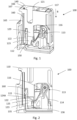
- connection arrangement 100 shows a connection arrangement 100 according to a possible embodiment.
- This connection arrangement 100 can, for example, be integrated in a connection terminal, such as a series terminal or a circuit board connection terminal.
- the connection arrangement 100 has a housing 110 made of an insulating material.
- a conductor connection space 111 is formed in an interior of the housing 110, within which the conductor 200 to be connected is connected.
- the conductor 200 to be connected can be introduced into the conductor connection space 111 via a conductor insertion opening 121 formed in the housing 110.
- a current bar 112 with its clamping section 122 projects into the conductor connection space 111, against which the conductor 200 to be connected can be clamped and connected by means of a clamping spring 113.
- the clamping spring 113 is designed as a leg spring which has a holding leg 114 and a clamping leg 115. The clamping leg 115 clamps the conductor 200 to be connected against the current bar 112 or against the clamping section 122 of the current bar 112.
- an actuating element 116 To transfer the clamping leg 115 from a clamping position to an open position, as shown in Fig. 1 and 2 shown is an actuating element 116
- the actuating element 116 is guided essentially linearly in a housing shaft 117 of the housing 110.
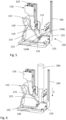
- the actuating element 116 has an actuating section 118 at its lower end in the actuating direction B of the actuating element 116, as shown for example in the illustration of the Fig. 5 and 6 can be seen.
- An actuating surface 119 is formed on an outer peripheral surface of the actuating section 118, which is in operative connection with the clamping leg 115, in particular when the clamping leg 115 is actuated.
- the actuating element 116 has a tool engagement surface 120, into which a tool, such as a screwdriver, can engage in order to actuate the actuating element 116 by guiding the actuating element 116 in the actuation direction B.
- a tool such as a screwdriver
- the connection arrangement 100 also has a slide arrangement 150 arranged in the housing 110.
- the clamping leg 115 of the clamping spring 113 can be held in the open position by means of the slide arrangement 150.
- the slide arrangement 150 can be designed in different ways, with the slide arrangement 150 each having a slide element 123, a return spring 135 and a display element 160.
- the slide element 123 has a first holding element 124A and a second holding element 124B, which interact with the clamping leg 115, in particular with the clamping edge 125 of the clamping leg 115, in order to hold the clamping leg 115 in the open position.
- the two holding elements 124A, 124B are arranged opposite one another.
- the two holding elements 124A, 124B each have a driving surface 126A, 126B and a holding surface 127A, 127B. If the clamping leg 115 is actuated by means of the actuating element 116 in order to be transferred from the clamping position to the open position, the clamping leg 115 can slide along the driving surface 126A, 126B of the holding element 124A, 124B, whereby the clamping leg 115 can exert a compressive force on the holding element 124A, 124B and thus on the slide element 123, so that the slide element 123 is displaced in the sliding direction S until the clamping leg 115 with its clamping edge 125 is detachable from the Driving surface 126A, 126B slides onto the holding surface 127A, 127B and can thereby latch onto the holding element 124A, 124B.
- the slide element 123 When sliding along the driving surface 126A, 126B, the slide element 123 can be moved in the same direction as the actuating element 116, which presses onto the clamping leg 115.
- the clamping leg 115 can slide with its clamping edge 125 along the driving surface 126A, 126B and latch onto the holding surface 127A, 127B.
- the driving surface 126A, 126B extends at an angle, in particular at a 90° angle, to the holding surface 127A, 127B. Viewed in the sliding direction S, the holding surface 127A, 127B extends below the driving surface 126A, 126B.
- the slide element 123 has a first wall surface 128A and a second wall surface 128B arranged opposite the first wall surface 128A.
- the two wall surfaces 128A, 128b are arranged at a distance from one another, with the conductor connection space 111 extending into the free space between the two wall surfaces 128A, 128b.
- the clamping leg 115 of the clamping spring 113 is pivotably positioned in the free space between the two wall surfaces 128A, 128b. The clamping of the conductor 200 to be connected takes place between the first wall surface 128A and the second wall surface 128B.
- the first wall surface 128A is designed to be so long that it forms an extension of the wall 129 of the housing 110 delimiting the conductor insertion opening 121, as shown in particular in Fig.1 can be seen.
- the conductor 200 inserted into the conductor insertion opening 111 is thereby guided further along the wall surface 128A, 128B of the slide element 123 following the wall 129, so that the first wall surface 128A and/or the second wall surface 128B form a conductor guide in the region of the conductor connection space 111.
- the two holding elements 124A, 124B are formed on the two wall surfaces 128A, 128B.
- the first holding element 124A is arranged on the first wall surface 128A and the second holding element 124B is arranged on the second wall surface 128B.
- the wall surfaces 128A, 128B are inclined in the direction of the conductor connection space 111, so that in the area of the two holding elements 124A, 124B, the two wall surfaces 128A, 128B are closer to each other than in the remaining area of the two wall surfaces 128A, 128B.
- the driving surface 126A, 126B of the two holding elements 124A, 124B extends here essentially transverse to the sliding direction S of the slide element 123.
- the holding surface 127A, 127B of the two holding elements 124A, 124B extends in the sliding direction S and thus perpendicular to the driving surface 126A, 126B.
- the first holding element 124A is formed here on a tab 145 punched out of the first wall surface 128A.
- the two wall surfaces 128A, 128B of the slide element 123 are designed to be so long that they form an extension of the wall 129 of the housing 110 that delimits the conductor insertion opening 121.
- the conductor 200 inserted into the conductor insertion opening 111 is thereby guided further along the wall surface 128A, 128B of the slide element 123 following the wall 129, so that the first wall surface 128A and/or the second wall surface 128B form a conductor guide in the region of the conductor connection space 111.
- the two wall surfaces 128A, 128b are connected to each other via a bottom wall 132 of the slide element 123.
- the bottom wall 132 has a pressure surface 133 pointing in the direction of the conductor connection space 111.
- a conductor 200 to be connected can strike against the pressure surface 133 in order to move the slide element 123 in the sliding direction S.
- the slide element 123 interacts with a return spring 135.
- the slide element 123 and the return spring 135 together with the display element 160 form the slide arrangement 150. If the clamping leg 115 slides along the driving surface 126A, 126B of the respective holding element 124A, 124B during its pivoting movement from the clamping position to the open position, the return spring 135 can be tensioned by the sliding movement of the slide element 123.
- the spring force of the return spring 135 can move the slide element 123 back to its starting position against the sliding direction S and the clamping leg 115 can latch onto the at least one holding element 124A, 124B. If a conductor 200 to be connected hits the pressure surface 133 of the slide element 123 during connection, the slide element 123 is moved in the sliding direction S and the return spring 135 is tensioned. As soon as the clamping leg 115 has disengaged from the two holding elements 124A, 124B, the spring force of the return spring 135 can move the slide element 123 back into its starting position against the sliding direction S.
- the return spring 135 is supported against a portion 136 of the current bar 112 which extends perpendicular to the clamping portion 122 of the current bar 112.
- the slide element 123 and the return spring 135 are formed integrally with one another. Both the slide element 123 and the return spring 135 can be formed from a metal material.
- the return spring 135 is designed as a leaf spring.
- the return spring 135 is elongated and has a first end 143 and a second end 144 arranged opposite the first end 143.
- the first end 143 of the return spring 135 is supported on the section 136 of the current bar 112.
- the second end 144 of the return spring 135 is connected in one piece to the slide element 123.
- the return spring 135 has a kind of tongue shape here.
- the return spring 135 is connected to the slide element 123 between the two wall surfaces 128A, 128B of the slide element 123.
- the return spring 135 is formed in one piece with the bottom wall 132 of the slide element 123.
- the return spring 135 together with the slide element 123 is a stamped and bent part.
- the display element 160 is connected to the slide element 123.
- the display element 160 can be used to display the connection status to a user.
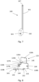
- the display element 160 is in Fig.7
- the display element 160 has a rod-shaped display section 161 and a coupling section 162 connected to the display section 161.
- the display element 160 can be connected to the slide element 123 via the coupling section 162, in particular via a locking connection.
- the coupling section 162 has a locking element 163 for this purpose, which can be locked into place by a counter-locking element 164 formed on the slide element 123. can be brought into engagement.
- the locking element 163 is designed here in the form of a locking pin or a locking nose and the counter-locking element 164 is designed here in the form of an opening.
- the counter-locking element 164 is formed on the second wall surface 128B of the slide element 123.
- the display element 160 is arranged in a fixed position relative to the slide element 123 via the coupling section 162. The display element 160 can follow the movement of the slide element 123 due to the connection to the slide element 123.
- the display section 161 is guided in a guide channel 165 formed on the housing 110.
- the guide channel 165 opens into an opening 166 in the housing 110, through which the position of the display section 161 or the display element 160 and thus the connection state can be seen from outside the housing 110.
- the rod-shaped display section 161 is positioned in the housing 110 such that the clamping section 122 of the current bar 112 is arranged between the rod-shaped display section 161 and the clamping spring 113.
- the display element 160 is thus arranged and guided outside the conductor connection space 111 so that the display element 160 does not hinder the actual connection of the conductor 200.
- Fig. 1, 2 and 5 show the clamping leg 115 of the clamping spring 113 in the open position, in which the clamping leg 115 is held with its clamping edge 125 on the holding elements 124A, 124B.
- the slide element 123 is here in a starting position in which the display element 160 with its display section 161, in particular the front surface 167 of the display section 161, is positioned flush with an outer surface 140 of the housing 110, as in Fig.1 can be recognized.
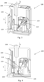
- a conductor 200 it can be inserted into the housing 110 in the insertion direction E via the conductor insertion opening 121, as shown in Fig. 3, 4 and 6 is shown.
- the clamping leg 115 of the clamping spring 113 is in the open position, in that the clamping leg 115 is in engagement with the two holding elements 124A, 124B of the slide arrangement 150 formed on the slide element 123. If the conductor 200 is inserted in the conductor insertion direction E into the conductor connection space 111, the conductor 200 against the pressure surface 133 of the slide element 123 which delimits the conductor connection space 111 in the insertion direction E.
- the slide element 123 is thereby pushed downwards in the sliding direction S, whereby the return spring 135 is tensioned by the second end 144 of the return spring 135 being moved together with the slide element 123 in the sliding direction S, and the clamping leg 115 is disengaged from the holding elements 124A, 124B of the slide arrangement 150.
- the clamping leg 115 can now pivot in the direction of the conductor 200 to be connected in order to clamp the conductor 200 against the clamping section 122 of the current bar 112.
- the display element 160 is also moved in the sliding direction S. As a result, the display element 160 dips into the guide channel 165 with the free end face 167 of the display section 161, so that the end face 167 is then no longer positioned flush with the outer surface 140 of the housing, but is immersed in the housing 110, as shown in Fig.3 can be recognized.
Landscapes
- Connections Arranged To Contact A Plurality Of Conductors (AREA)
Applications Claiming Priority (1)
| Application Number | Priority Date | Filing Date | Title |
|---|---|---|---|
| DE102022134060.0A DE102022134060A1 (de) | 2022-12-20 | 2022-12-20 | Anschlussanordnung |
Publications (1)
| Publication Number | Publication Date |
|---|---|
| EP4391236A1 true EP4391236A1 (fr) | 2024-06-26 |
Family
ID=89119143
Family Applications (1)
| Application Number | Title | Priority Date | Filing Date |
|---|---|---|---|
| EP23214146.5A Pending EP4391236A1 (fr) | 2022-12-20 | 2023-12-05 | Ensemble de raccordement |
Country Status (3)
| Country | Link |
|---|---|
| EP (1) | EP4391236A1 (fr) |
| CN (1) | CN118232088A (fr) |
| DE (1) | DE102022134060A1 (fr) |
Families Citing this family (2)
| Publication number | Priority date | Publication date | Assignee | Title |
|---|---|---|---|---|
| DE202024102624U1 (de) * | 2024-05-22 | 2025-08-25 | WAGO Verwaltungsgesellschaft mit beschränkter Haftung | Leiteranschlussklemme |
| DE202024104672U1 (de) * | 2024-08-19 | 2025-11-20 | WAGO Verwaltungsgesellschaft mit beschränkter Haftung | Federkraftklemmanschluss und Leiteranschlussklemme |
Citations (4)
| Publication number | Priority date | Publication date | Assignee | Title |
|---|---|---|---|---|
| JP2009230859A (ja) * | 2008-03-19 | 2009-10-08 | Toyo Giken Kk | 端子台 |
| WO2021095676A1 (fr) * | 2019-11-11 | 2021-05-20 | オムロン株式会社 | Bornier |
| US11101583B2 (en) * | 2018-03-14 | 2021-08-24 | Omron Corporation | Terminal block displaying connection state |
| DE102021101343A1 (de) * | 2021-01-22 | 2022-07-28 | Phoenix Contact Gmbh & Co. Kg | Anschlussanordnung, Anschlusseinrichtung sowie elektronisches Gerät |
-
2022
- 2022-12-20 DE DE102022134060.0A patent/DE102022134060A1/de active Pending
-
2023
- 2023-12-05 EP EP23214146.5A patent/EP4391236A1/fr active Pending
- 2023-12-19 CN CN202311748115.4A patent/CN118232088A/zh active Pending
Patent Citations (4)
| Publication number | Priority date | Publication date | Assignee | Title |
|---|---|---|---|---|
| JP2009230859A (ja) * | 2008-03-19 | 2009-10-08 | Toyo Giken Kk | 端子台 |
| US11101583B2 (en) * | 2018-03-14 | 2021-08-24 | Omron Corporation | Terminal block displaying connection state |
| WO2021095676A1 (fr) * | 2019-11-11 | 2021-05-20 | オムロン株式会社 | Bornier |
| DE102021101343A1 (de) * | 2021-01-22 | 2022-07-28 | Phoenix Contact Gmbh & Co. Kg | Anschlussanordnung, Anschlusseinrichtung sowie elektronisches Gerät |
Also Published As
| Publication number | Publication date |
|---|---|
| DE102022134060A1 (de) | 2024-06-20 |
| CN118232088A (zh) | 2024-06-21 |
Similar Documents
| Publication | Publication Date | Title |
|---|---|---|
| EP0920714B2 (fr) | Appareil electrique ou electronique | |
| EP2324533B1 (fr) | Borne de connexion électrique | |
| DE102020104140A1 (de) | Anschlussanordnung | |
| WO2010022955A1 (fr) | Borne de raccordement électrique | |
| EP3320582B1 (fr) | Borne de connexion | |
| DE102017129407B4 (de) | Elektrische Anschlussklemme | |
| EP4391236A1 (fr) | Ensemble de raccordement | |
| DE102019109975A1 (de) | Anschlussklemme | |
| DE202007001701U1 (de) | Universalkontakt | |
| DE102021117396A1 (de) | Anschlussanordnung, Anschlussklemme und elektronisches Gerät | |
| EP4033610A1 (fr) | Agencement de connexion électrique | |
| DE102019131146B4 (de) | Anschlussanordnung | |
| DE2039460A1 (de) | Mechanischer Rahmenaufbau fuer Fernmeldeanlagen | |
| DE102016112831B4 (de) | Anschlussklemme | |
| DE10103187B4 (de) | Elektrische Klemme | |
| DE102020104138A1 (de) | Anschlussanordnung | |
| EP4084226A1 (fr) | Agencement de borne, borne de connexion et appareil électronique | |
| DE102022109217A1 (de) | Anschlussanordnung | |
| EP3813198A1 (fr) | Dispositif de raccordement permettant de raccorder une conduite électrique | |
| LU501848B1 (de) | Anschlussanordnung | |
| EP4010945B1 (fr) | Dispositif de connexion, borne de connexion et dispositif électronique | |
| DE102019120306B4 (de) | Leiteranschlussklemme zum Anschluss wenigstens eines elektrischen Leiters | |
| EP0352679A2 (fr) | Appareillage interrupteur électrique | |
| DE102022117906A1 (de) | Anschlussanordnung | |
| WO2024017653A1 (fr) | Ensemble de connexion |
Legal Events
| Date | Code | Title | Description |
|---|---|---|---|
| PUAI | Public reference made under article 153(3) epc to a published international application that has entered the european phase |
Free format text: ORIGINAL CODE: 0009012 |
|
| STAA | Information on the status of an ep patent application or granted ep patent |
Free format text: STATUS: THE APPLICATION HAS BEEN PUBLISHED |
|
| AK | Designated contracting states |
Kind code of ref document: A1 Designated state(s): AL AT BE BG CH CY CZ DE DK EE ES FI FR GB GR HR HU IE IS IT LI LT LU LV MC ME MK MT NL NO PL PT RO RS SE SI SK SM TR |
|
| STAA | Information on the status of an ep patent application or granted ep patent |
Free format text: STATUS: REQUEST FOR EXAMINATION WAS MADE |
|
| 17P | Request for examination filed |
Effective date: 20241218 |