EP4393555A1 - Wasserlöschsystem und verfahren zur durchführung eines pumpbetriebs darin - Google Patents
Wasserlöschsystem und verfahren zur durchführung eines pumpbetriebs darin Download PDFInfo
- Publication number
- EP4393555A1 EP4393555A1 EP22216728.0A EP22216728A EP4393555A1 EP 4393555 A1 EP4393555 A1 EP 4393555A1 EP 22216728 A EP22216728 A EP 22216728A EP 4393555 A1 EP4393555 A1 EP 4393555A1
- Authority
- EP
- European Patent Office
- Prior art keywords
- pump
- fluid
- test run
- start condition
- control unit
- Prior art date
- Legal status (The legal status is an assumption and is not a legal conclusion. Google has not performed a legal analysis and makes no representation as to the accuracy of the status listed.)
- Withdrawn
Links
Images

Classifications
-
- A—HUMAN NECESSITIES
- A62—LIFE-SAVING; FIRE-FIGHTING
- A62C—FIRE-FIGHTING
- A62C37/00—Control of fire-fighting equipment
- A62C37/50—Testing or indicating devices for determining the state of readiness of the equipment
-
- A—HUMAN NECESSITIES
- A62—LIFE-SAVING; FIRE-FIGHTING
- A62C—FIRE-FIGHTING
- A62C35/00—Permanently-installed equipment
- A62C35/58—Pipe-line systems
-
- A—HUMAN NECESSITIES
- A62—LIFE-SAVING; FIRE-FIGHTING
- A62C—FIRE-FIGHTING
- A62C35/00—Permanently-installed equipment
- A62C35/58—Pipe-line systems
- A62C35/68—Details, e.g. of pipes or valve systems
Definitions
- the present invention relates to a water extinguishing system and a method for controlling a pump operation, in particular a pump test run, in such a water extinguishing system.
- Water extinguishing systems according to the invention are in particular sprinkler, water spray and foam extinguishing systems, wherein the invention is not limited to special types of water extinguishing systems but may encompass others.
- the concept commonly connecting water extinguishing systems is that these systems encompass an extinguishing fluid, typically comprising or consisting of water, being pumped from a fluid supply line for providing the extinguishing fluid to a fluid distribution line that distributes the extinguishing fluid throughout a pipe network of the water extinguishing system to one or more - typically a plurality of - fluid outlets, such as sprinklers or fluid nozzles.
- the present invention relates in particular to water extinguishing systems comprising a fluid supply line for providing an extinguishing fluid, a fluid distribution line for distributing the extinguishing fluid to at least one extinguishing fluid outlet, a pump comprising a housing, a pump inlet in fluid connection with the fluid supply line and a pump outlet in fluid connection with the fluid distribution line and a control unit.
- the at least one extinguishing fluid outlet is part of a pipe system of the water extinguishing system, the pipe system being distributed throughout a room or place in which the water extinguishing system is provided for the purpose of fire protection.
- the water extinguishing system may further comprise at least one valve element provided within the fluid distribution line comprising a valve inlet in fluid connection with the pump outlet and a valve outlet in fluid connection with the at least one extinguishing fluid outlet, the valve element configured to control a flow of the extinguishing fluid between the valve inlet and the valve outlet based on an alarm state of the water extinguishing system.
- the valve element may preferably be an alarm valve as known in the art and the alarm state may particularly refer to a state in which an alarm is indicated as a first state and a state in which no alarm is indicated as a second state.
- a fluid supply line may particularly referto an element which serves to supply the extinguishing fluid towards the pump of the water extinguishing system.
- a fluid supply line may particularly correspond to a pipe.
- the fluid supply line, in particular the pipe may, at its one end, be fluidly connected to the pump and, at its other end, be fluidly connected to a fluid storage, such as a reservoir, in which the extinguishing fluid can be stored, or a fluid supply element, such as a drinking water supply from which drinking water can be supplied to the water extinguishing system as extinguishing fluid through the supply line.
- a fluid distribution line may refer to an element which serves to distribute the extinguishing fluid from the pump into the water extinguishing system towards the fluid outlets.
- the fluid distribution line may particularly correspond to a line which serves to distribute the extinguishing fluid pumped by the pump throughout the pipe network.
- the fluid distribution line may particularly be embodied as a pipe.
- the fluid distribution line may, at its first end, be fluidly connected to the pump, and, at its second end, be fluidly connected to at least one fluid outlet.
- the fluid distribution line may, at its second end, be fluidly connected to a pipe network comprising at least one fluid outlet.
- the fluid distribution line describes in particular a pipe that either directly feeds a branch pipe or a single sprinkler or nozzle on a branch pipe that is not a tailpipe and is longer than 300 mm.
- a pump that may be provided in the water extinguishing system may particularly be a motor-driven pump, typically an electrical pump or a diesel pump, configured to pump the extinguishing fluid from the supply line towards the distribution line for distribution to the fluid outlets.
- the pump may particularly separate the fluid supply line and the fluid distribution line.
- the pump needs not necessarily be part of either one, but may also be situated away from the fluid supply line and the fluid distribution line, as long as it allows to pump the fluid from the fluid supply line to the fluid distribution line.
- the pump may hereby be, at its one end, in fluid connection with the fluid supply line and, at its other end, be in fluid connection with the fluid distribution line.
- the fluid supply line and the fluid distribution line correspond to pipes, this means that the pump is provided in between these pipes and used for pumping the fluid from one (supply) pipe to the other (distribution) pipe.
- extinguishing fluid may particularly refer to a fluid which is used to extinguish and/or fight fires.
- This extinguishing fluid may in particular be extinguishing water provided with or without additives.
- the extinguishing fluid may contain in particular a foam, an anti-freezing agent or similar. If possible, the additives should be selected so as to be optimal for the respective application of the water extinguishing system.
- the extinguishing fluid may also be pure extinguishing water. Other extinguishing fluids are also conceivable.
- a test line may particularly refer to a water measuring device comprising a flow meter, calming sections and regulating valves for testing the water rate.
- the test line is preferably provided as a branch line from the fluid supply line or the fluid distribution line of the water extinguishing system, even more particularly as a branch line from the fluid distribution line, which is positioned behind the pump in flow direction.
- the test line may further comprise an opening element.
- an opening element is understood in particular to be a sliding element within an opening unit, such as a valve, which can be operated manually in accordance with the prior art. Opening is effected by moving the sliding element from a locking to an unlocking position.
- Opening the opening element in the test line enables a volume flow through the test line, by means of which a pump test run can be carried out. Closing is then effected by moving the sliding element from the unlocking position to the locking position. This interrupts the volume flow through the test line again.
- a fluid bypass line may particularly refer to an additional fluid-conducting line, which is provided in addition to the test line and may either also branch off from the fluid supply line, the fluid distribution line or from the test line.
- the fluid bypass line may typically have a cross-section that is much smaller than that of the test line. In some embodiments, for example, the cross-section of the fluid bypass line corresponds to only 2 to 10% of the cross-section of the test line, in other embodiments even less. Usually, the cross-section of the fluid bypass line is selected to conduct in particular 2% of the flow of the pump.
- the fluid bypass line is also called emergency line.
- the fluid bypass line is designed in such a way that it conducts the extinguishing fluid pumped by the pump away from the fluid outlets even if the opening element in the test line is in the locking position.
- the fluid bypass line thus serves to conduct the extinguishing fluid around the opening element away from the at least one fluid outlet and/or from the pipe system comprising the at least one fluid outlet if there is one.
- the bypass line may conduct the extinguishing fluid away from the fluid distribution line towards a drain outlet.
- the bypass line may conduct the extinguishing fluid away from the fluid distribution line towards the fluid supply line.
- the bypass line may conduct the extinguishing fluid away from the fluid distribution line towards a fluid storage or fluid reservoir configured to store the extinguishing fluid.
- test line is usually used for this purpose, enabling a pump test to be carried out while preventing the extinguishing fluid from causing weekly flooding of the areas monitored by the water extinguishing system during the weekly required pump test of the pump.
- This test line can be opened by means of the opening element for the purpose of the pump test run and closed again after the pump test run has been completed. In this way, it is possible to provide a kind of test circuit for the period of the pump test run, thus avoiding flooding of the monitored areas.
- the test line is configured in such a way that it conducts the extinguishing fluid flowing through it back into a fluid reservoir and/or an intermediate tank which is in fluid connection with the fluid supply line. This means that the extinguishing fluid passing through the test line during the pump test run can still be used by the water extinguishing system.
- the fluid bypass line can also be configured to conduct the extinguishing fluid flowing through it back into the reservoir and/or an intermediate tank.
- the fluid bypass line may be configured such that the extinguishing fluid passing through it is conducted into a waste water tank and/or a waste water pipe and/or otherwise discharged from the pipe system and is not available to the system again.
- the water extinguishing systems of the prior art comprised a control unit that is capable of controlling the pump and, in particular, activating the pump for the purpose of running the pump test run and aborting the pump test run - while typically maintaining operation of the pump for pumping the extinguishing fluid to fight the fire event - if an emergency event, e.g. a fire event, occurs.
- an emergency even such as a fire event or other hazard in an area monitored by the water extinguishing system, may be one reason to abort an otherwise automated pump test run.
- such an event may not only be an emergency event.
- the abortion of the test run and/or the shutting down of the pump also need to be automated, whereby this automation should also ensure that the pump test run is not aborted unnecessarily, i.e. that an appropriate reaction is made with respect to the pump and the pump test run.
- one object of the present invention is to create a solution which enables the pump test run to be activated and aborted automatically. More particularly, it is an object of the present invention to provide for a solution which allows appropriately reacting to irregularities and/or disruptions during the automated pump test run, thereby allowing for a more sophisticated automated decision on the actions to be taken in view of the occurrences registered during a pump test run.
- a water extinguishing system of the type mentioned initially in which the water extinguishing system comprises a plurality of sensors in signal connection with the control unit, wherein each of the plurality of sensors is configured to obtain at least one parameter value of a parameter indicative of an operating state of the water extinguishing system, wherein control unit is configured to receive the at least one parameter value from at least one of the plurality of sensors, to determine, based on an evaluation of the at least one parameter value, at least one pump operation condition and to control a pump operation comprising a pump test run based on the at least one pump operation condition.
- a plurality of sensor readings providing information collected at several positions within the water extinguishing system are used to determine at least one pump operation condition, preferably at least two pump operation conditions, on the basis of which the control unit may control the pump operation including the pump test run.
- the controlling of the pump operation including the pump test run may particularly comprise an initiating of the pump test run if the evaluation of the parameter values of the parameters as obtained from the sensors allows for the conclusion that the pump test run may be performed without any problems. In this case, it is assumed that the pump operation condition is met, i.e. that it is determined that all requirements necessary for performing the pump test run are fulfilled.
- the controlling of the pump operation may comprise not initiating the pump test run of the evaluation of the parameter values of the parameters as obtained from the sensor reveals that there are irregularities or disruptions present that make it problematic to perform the pump test run.
- the controlling may encompass aborting the pump operation including the pump test run once it has been started if the evaluation of the parameter values reveals that, while the pump test run could initially have been initiated, in the meantime some occurrence has occurred that makes it necessary to abort the pump test run.
- the controlling may also encompass running the pump operation including the pump test run until the pump test run is finished and then terminating the pump test run.
- the controlling may further, alternatively or additionally, encompass monitoring the progress of the pump operation including the pump test run and providing an indication of the progress as monitored to a central control unit such as a fire alarm centre.
- the controlling may encompass performing all steps that would otherwise be performed by trained personnel in an automated manner by the control unit.
- the pump test run may be executed for a certain time frame. This time should be chosen in dependence on the pump properties and selected such as to ensure a proper pump test run. It is also conceivable that the pump test run time is determined during the pump test run procedure itself. In some embodiments, the pump test run time depends on sensor data, preferably the pump test run will be maintained until one or more parameter values from sensors meet a threshold criterion. In some embodiments, such parameter values may comprise any combination of parameter values of parameters indicative of an operating state of the water extinguishing system. In such a case, it can be understood that the final pump test run time is changed or set to be derived from the time between starting the pump and meeting the threshold criteria.
- the pump test run may be aborted.
- the pump test run time may be 15 minutes. In some embodiments, it may be shorter, such as 5 minutes, 10 minutes, or anything between 1 second to 15 minutes. In some embodiments, it may be longer, i.e. 15 minutes, such as 20 minutes, 25 minutes or any other value above 15 minutes.
- the pump test run is, inter alia, used to determine the functionality of the pressure switch, respectively pressure switches, that are used for starting the pump. These pressure switches are typically provided in a redundant manner for sake of security (such as to have a second pressure switch in case a first pressure switch does not work properly).
- the invention is based on the realization that the automation of the pump operation, and, in particular, the pump test run, requires a continuous monitoring of the operating state of the water extinguishing system. More particularly, the invention is based on the realization that the water extinguishing system and its operating state are fluent and that it cannot be assumed that, just because the operating state was appropriate for a pump test run when the pump test run was started, it remains appropriate for the entire length of the pump test run.
- the water extinguishing system may be in an alarm state due to a reduced pressure of fluid, such as air or gas within the pipe network of the water extinguishing fluid.
- a reduced pressure of fluid such as air or gas within the pipe network of the water extinguishing fluid.
- This reduced pressure may particularly be determined using a respective pressure switch provided in the system.
- the water extinguishing system may particularly comprise a valve, such as an alarm valve, typically implemented as a wet or dry alarm valve.
- the pressure switch may e.g. provided downstream of the valve element.
- the term pump operation condition refers to any condition, determined on the basis of the parameter value or parameter values given, under which the pump may continue to operate.
- a pressure sensor for measuring the pressure of the extinguishing fluid in the fluid distribution line
- a temperature sensor for measuring the temperature of the pump and if the pressure of the extinguishing fluid is above a pre-set threshold above which proper operation of the water extinguishing system is ensured and if the temperature of the pump is below a pre-set threshold below which it may be assumed that the pump does not overheat, this, in combination, may be viewed as a pump operation condition under which the pump test run may continue.
- the pressure sensor indicates a pressure drop, leading to the pressure falling below the threshold this may be seen as an indication that the pump test run should be aborted. If such pressure drop is measured prior to starting the pump, this may - irrespective of the temperature of the pump measured - be a sign to not start the pump test run at all, but instead start the pump operation in order to properly pump water in the direction of the fluid outlets.
- the control unit may evaluate the sensor readings and determine whether the water extinguishing system is in a readiness state in which no irregularities and/or disruptions are present or in an exception state, such as an alarm state, in which something irregular and/or disruptive, such as an emergency event or a leakage, has been detected.
- an exception state such as an alarm state
- something irregular and/or disruptive such as an emergency event or a leakage
- the fulfilment or non-fulfilment of the pump operation condition and, hence, the decision of whether or not to initiate or continue the pump test run may particularly be determined by comparing the sensor readings to a standard range or a standard threshold value that provides for a pre-set indication as to what is the norm and what is an exception.
- the control unit enforces a corresponding action to allow for an appropriate reaction by the water extinguishing system.
- the control unit may use this to determine that a pre-start condition is not met and, hence, may lead the control unit to prevent initiating the pump test run.
- the temperature reading indicates a temperature below the threshold prior to the start of the pump test run, this may cause the control unit to consider that the pre-start condition is met and, hence, initiate the pump test run.
- the control unit may find that the post-start condition is not met anymore and abort the pump test run.
- the post-start condition is determined, as described herein above, based on an activation state and/or a response time of the pressure switch at or within the fluid distribution system.
- a further parameter considered when determining the post-start condition is the temperature of the extinguishing fluid at the pump inlet which may indicate the temperature at or within the pump and may be used to determine whether the pump could be sufficiently cooled during the pump test run. If this is not the case, the post-start condition may indicate that the pump test run should be aborted.
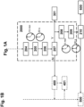
- Fig. 1A Another parameter value reviewed in the exemplary embodiment of Fig. 1A in order to check whether pre-start conditions are met is the temperature at the pump housing. If the temperature at the pump housing is already very high, it may not be beneficial to start the pump test run. Accordingly, this may lead to the pre-start condition not being fulfilled. On the other hand, if the temperature is within a certain acceptable range, the pre-start condition may been considered as being fulfilled.
- a sensor reading is provided that indicates the room temperature of the room in which the pump is situated.
- the pump is prevented of starting the pump test run.
- a service device for forwarding the indication to a portable monitor at a service person responsible for servicing the water extinguishing system in order to inform said person that the pump operation and, hence, the pump test run, has not taken place.
- This indication will, in the following, be referred to as a pump test run termination indication. That is, in step 401, a pump test run termination indication is signalled so as to inform the responsible personnel of the termination, respectively the non-initiation, of the pump test run.
- step 204 the controlling of the magnetic valve is deactivated since the pump test run will proceed.
- the pump test run is executed for a certain time. In the specific embodiment of Fig. 1B , this time amounts to 15 minutes. However, it is noted that the invention is not limited to this amount of time.
- the pump test run time may also be below 15 minutes, for example 5 minutes, 10 minutes, or anything between 1 second to 15 minutes or even above 15 minutes, such as 20 minutes, 25 minutes or any other value above 15 minutes.
- the time should be chosen in dependence on the pump properties and selected such as to ensure a proper pump test run.
- the sensors may further encompass a pressure sensor and/or a flow rate sensor and/or a combined sensor for measuring pressure and flow rate at or within the bypass line branching off from the distribution line and being configured to conduct the extinguishing fluid away from the fluid distribution line towards a drain outlet and/or the supply pipe system.
- a pressure sensor and/or a flow rate sensor and/or a combined sensor for measuring pressure and flow rate at or within the bypass line branching off from the distribution line and being configured to conduct the extinguishing fluid away from the fluid distribution line towards a drain outlet and/or the supply pipe system.
- the water extinguishing system corresponds to a pre-action dry system or a deluge system
- it is the control unit and/or a control centre which is in signal connection with respective fire detection devices and receives an indication about a fire event from one or more of those devices that opens the valve 31 which causes the pump to be started as described herein above.
- the test line 40 is provided with an opening element 41, such as a magnetic valve, which may be changed from an open state in which the test circuit comprising the fluid supply line 20, the fluid distribution line 30 and the test line 40 is opened to a closest state in which the test circuit is closed. Branching from the test line 40 is bypass line 42.
- Bypass line 42 has a smaller cross section compared to the test line 40 and, hence, is capable of conducting only a portion of the extinguishing fluid that might be conducted through the test line if the opening element 41 is opened.
- the bypass line 42 has a cross section that amounts to roughly 2% of the cross section of the test line 40, meaning that the bypass line 42 may also conduct only 2% of the extinguishing fluid that might be conducted by the test line 40.
- the test line 40 may branch from a different line or even from the pump in the water extinguishing system 1.
- the important part about the test line 40 is that it is fluidly connected to the pump and may be used to conduct extinguishing fluid during a pump test run.
- test line 40 is illustrated as branching into the fluid supply line 20, it may also branch into the fluid reservoir 70 and/or another fluid connection line leading to the pump 10. That is, the test line 40 is not limited to branching from the fluid supply line 20 and/or the fluid distribution line 30.
- bypass line 42 is illustrated as branching from the test line 40, it is also conceivable that the bypass line 42 branches directly from the fluid distribution line 30 or the pump 10. Similarly, although the bypass line 42 is illustrated as branching into the test line 40, it may also branch into the fluid supply line 20, the fluid reservoir 70, another fluid connection line leading to the pump 10 and/or any discharge outlet. That is, the bypass line 42 is likewise not limited to a particular branching scheme, as long as it fulfils its purpose of bypassing the fluid around the opening element of test line 40.
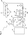
- the pump 10 is in signal connection with control unit 50 Further, the pump 10 is provided with a switch 11, which is in direct connection with pressure switches 32a and 32b. As described herein above, in order to initiate pump operation, a small discharge valve adjacent to pressure switches 32a and 32b is opened, causing a small drop in pressure close to the pressure switches 32a and 32b. This may cause the pressure switches 32a and 32b to switch. Now, both pressure switches are in direct connection with the activation switch 11 at the pump 10, whereby, in the exemplary embodiment of Fig. 2 , pressure switch 32a is switching activation switch 11 to activate the pump.
- the pump 10 is configured to perform the pump test run through the bypass line 42. Accordingly, in the specific embodiment of Fig. 2 it is not required that the opening element in test line 40 is opened. Instead, the pump test run of the pump 10 is performed using the fluid of the bypass line 42. As discussed herein above, this means that it should be ensured that there are no deposits and/or cavitation in bypass line 42 such as to ensure a proper amount of fluid being conducted therein which allows to properly cool the pump 10.
- the bypass line 42 is provided, in the specific embodiment of Fig. 2 , with a sensor 25 whose functioning will be described further below.
- control unit 50 may control the pump operation, in particular the pump test run, by e.g. executing the method according to Figs. 1A and 1B as described herein above.
- the water extinguishing system 1 further comprises a plurality of sensors 21, 22, 23, 24, 25, 26 and 27. It is noted that any of the sensors 21, 22, 23, 24, 25, 26 and 27 may be implemented as any sensor as described herein above, such as a pressure sensor, a temperature sensor, a vibration sensor, a flow sensor, a leakage sensor, a current sensor and/or a sensor for detecting the activation state and/or the response time of a pressure switch and/or any other sensor previously described. In the specific embodiment of Fig. 2 , each of the sensors is in signal communication with the control unit 50.
- the sensor 21 is implemented as a vibration sensor.
- the sensor 22 is implemented as a temperature sensor and the sensor 23 is implemented as a leakage sensor.
- the sensor 24 is implemented as a sensor for sensing the activation state of a pressure switch 32.
- the sensor 25 is implemented as a flow sensor sensing the flow rate through the bypass line 42, and the sensor 26 is implemented as a pressure sensor for determining the pressure behind the valve 31 , i.e. between the valve 31 and the pipe system 60 in which the fluid outlets 61 are arranged.
- sensor 21 is used to monitor a vibration of the pump 10, in particular at the pump housing of the pump 10.
- the vibration monitoring may be used to derive a pump operation condition, in particular a post-start condition.
- this may be indicative of a disruption and/or irregularity with the pump operation and/or the fluid supply line 20, the fluid distribution line 30 and/or the bypass line 42, such as cavitation in any of these lines which may lead to insufficient fluid conduction and, as a result, to overheating of the pump 10.
- the change in vibration may cause an evaluation by the control unit 50 which renders the result that the post-start condition is not met anymore and the pump test run should be aborted.
- a cavitation may also mean that the pump test run should not be started at all, i.e. might also be indicative for a pre-start condition not being met.
- the vibration of the pump 10 may only be obtained once the pump has been started.
- the sensor reading provided by the vibration sensor 21 may only serve to determine a post-start condition.
- the sensor 22 is used to monitor the temperature of the extinguishing fluid at the pump outlet of the pump 10 towards the distribution line.
- This monitoring of the temperature of the extinguishing fluid at the pump outlet may likewise be used to determine whether or not a post-start condition is fulfilled.
- the control unit 50 may receive sensor readings from sensor 22 that show a continuous increase in extinguishing temperature at the pump outlet. This may be considered as an indication that the pump 10 is heating up, potentially due to insufficient cooling.
- the control unit may consider a post-start condition to not be fulfilled and abort the pump test run.
- the leakage measurement may also be used to be indicative of a pre-start condition. That is, the control unit 50 may be configured to prevent the pump operation, in particular the pump test run, from being initiated in case the fluid drop rate is above a certain threshold. As such, the fluid drop rate and, hence, the leakage measured by sensor 23 may be considered for both, pre-start and post-start conditions of the pump 10.
- the sensor 24 is, in the embodiment according to Fig. 2 , provided at pressure switches 32a and 32b and may monitor the activation of these pressure switches 32a and 32b in response to pressure changes.
- the sensor 24 is further configured to determine the response time of the pressure switches 32a and 32b.
- the sensor 24 provides a reading about whether or not the pressure switches 32a and 32b have activated and, if it has activated, at which reaction time it has activated, to control unit 50.
- the control unit 50 may use this sensor reading to determine whether the pump operation, in particular the pump test run, shall be continued or not as described in relation to Figs. 1A and 1B .
- the sensor 27 is implemented, in the specific embodiment according to Fig. 2 , as a pressure sensor for measuring the pressure of the fluid inside the pipe system 60 including the fluid outlets 61.
- the fluid inside the pipe system 60 may hereby likewise either correspond to air or gas for a dry system including a dry alarm valve 31 or to a liquid for a wet system including a wet alarm valve 31.
- the pressure sensor 27 should be able to monitor a constant pressure inside the pipe system 60. If the pressure gradually decreases overtime with a rate exceeding a certain threshold rate, this may be considered as an indication that leakage is present within the pipe system 60.
- a drop in pressure below a certain threshold value may be considered as an indication that the water extinguishing system 1 is in an alarm state. This may be counter-indicative to starting and/or continuing the pump test run. As such, the pressure measurement by the sensor 27 may be used by the control unit to determine a pre-start and/or a post-start condition being met.
- the position and selection of sensors is only exemplary.
- the sensors used may be different sensors and, accordingly, their respective position in the system may be different.
- the skilled person will appreciate, from the above general description the variety of sensors that may be used and their respective positioning necessary for this purpose.
- a respective pressure sensor should be provided at or within the fluid reservoir 70.
Landscapes
- Health & Medical Sciences (AREA)
- Public Health (AREA)
- Business, Economics & Management (AREA)
- Emergency Management (AREA)
- Control Of Positive-Displacement Pumps (AREA)
Priority Applications (3)
| Application Number | Priority Date | Filing Date | Title |
|---|---|---|---|
| EP22216728.0A EP4393555A1 (de) | 2022-12-27 | 2022-12-27 | Wasserlöschsystem und verfahren zur durchführung eines pumpbetriebs darin |
| EP23838019.0A EP4642539A1 (de) | 2022-12-27 | 2023-12-21 | Wasserlöschsystem und verfahren zur durchführung eines pumpbetriebs darin |
| PCT/EP2023/087314 WO2024141410A1 (en) | 2022-12-27 | 2023-12-21 | Water extinguishing system and method of performing a pump operation therein |
Applications Claiming Priority (1)
| Application Number | Priority Date | Filing Date | Title |
|---|---|---|---|
| EP22216728.0A EP4393555A1 (de) | 2022-12-27 | 2022-12-27 | Wasserlöschsystem und verfahren zur durchführung eines pumpbetriebs darin |
Publications (1)
| Publication Number | Publication Date |
|---|---|
| EP4393555A1 true EP4393555A1 (de) | 2024-07-03 |
Family
ID=84603995
Family Applications (2)
| Application Number | Title | Priority Date | Filing Date |
|---|---|---|---|
| EP22216728.0A Withdrawn EP4393555A1 (de) | 2022-12-27 | 2022-12-27 | Wasserlöschsystem und verfahren zur durchführung eines pumpbetriebs darin |
| EP23838019.0A Pending EP4642539A1 (de) | 2022-12-27 | 2023-12-21 | Wasserlöschsystem und verfahren zur durchführung eines pumpbetriebs darin |
Family Applications After (1)
| Application Number | Title | Priority Date | Filing Date |
|---|---|---|---|
| EP23838019.0A Pending EP4642539A1 (de) | 2022-12-27 | 2023-12-21 | Wasserlöschsystem und verfahren zur durchführung eines pumpbetriebs darin |
Country Status (2)
| Country | Link |
|---|---|
| EP (2) | EP4393555A1 (de) |
| WO (1) | WO2024141410A1 (de) |
Citations (5)
| Publication number | Priority date | Publication date | Assignee | Title |
|---|---|---|---|---|
| GB2280369A (en) * | 1993-07-29 | 1995-02-01 | Project Fire Engineers Limited | Testing a fire sprinkling system |
| US5680329A (en) * | 1996-07-05 | 1997-10-21 | Lloyd; Steven J. | Fire protection code compliance verification system and method |
| WO2020035385A1 (de) | 2018-08-14 | 2020-02-20 | Minimax Viking Research & Development Gmbh | Wasserlöschanlage und zugehöriges verfahren zum kontrollieren der wasserlöschanlage |
| KR102132995B1 (ko) * | 2019-10-11 | 2020-07-13 | 동원펌프주식회사 | 자동 시운전 및 고착방지 시운전이 가능한 소방펌프 시스템 |
| EP3842101A1 (de) | 2019-12-27 | 2021-06-30 | Minimax Viking Research & Development GmbH | Wasserlöschanlage und verfahren zum steuern eines pumpentestlaufs in einer wasserlöschanlage |
-
2022
- 2022-12-27 EP EP22216728.0A patent/EP4393555A1/de not_active Withdrawn
-
2023
- 2023-12-21 WO PCT/EP2023/087314 patent/WO2024141410A1/en not_active Ceased
- 2023-12-21 EP EP23838019.0A patent/EP4642539A1/de active Pending
Patent Citations (7)
| Publication number | Priority date | Publication date | Assignee | Title |
|---|---|---|---|---|
| GB2280369A (en) * | 1993-07-29 | 1995-02-01 | Project Fire Engineers Limited | Testing a fire sprinkling system |
| US5680329A (en) * | 1996-07-05 | 1997-10-21 | Lloyd; Steven J. | Fire protection code compliance verification system and method |
| WO2020035385A1 (de) | 2018-08-14 | 2020-02-20 | Minimax Viking Research & Development Gmbh | Wasserlöschanlage und zugehöriges verfahren zum kontrollieren der wasserlöschanlage |
| US20210260425A1 (en) * | 2018-08-14 | 2021-08-26 | Minimax Viking Research & Development Gmbh | Water Extinguishing System and Associated Method for Controlling the Water Extinguishing System |
| KR102132995B1 (ko) * | 2019-10-11 | 2020-07-13 | 동원펌프주식회사 | 자동 시운전 및 고착방지 시운전이 가능한 소방펌프 시스템 |
| EP3842101A1 (de) | 2019-12-27 | 2021-06-30 | Minimax Viking Research & Development GmbH | Wasserlöschanlage und verfahren zum steuern eines pumpentestlaufs in einer wasserlöschanlage |
| US20210197004A1 (en) * | 2019-12-27 | 2021-07-01 | Minimax Viking Research & Development Gmbh | Water Extinguishing System and Method for Controlling a Pump Test Run in a Water Extinguishing System |
Also Published As
| Publication number | Publication date |
|---|---|
| EP4642539A1 (de) | 2025-11-05 |
| WO2024141410A1 (en) | 2024-07-04 |
Similar Documents
| Publication | Publication Date | Title |
|---|---|---|
| US12168156B2 (en) | Water extinguishing system and method for controlling a pump test run in a water extinguishing system | |
| US11253738B2 (en) | Water extinguishing system and associated method for controlling the water extinguishing system | |
| KR102389705B1 (ko) | 고착방지기능을 갖는 소방펌프 패키지 시스템 및 소방펌프 패키지 시스템의 고착방지방법 | |
| KR102452095B1 (ko) | 건축물 소방수 급배수장치 | |
| EP4393555A1 (de) | Wasserlöschsystem und verfahren zur durchführung eines pumpbetriebs darin | |
| KR20230010178A (ko) | 고착 감지 기능성 펌프, 펌프 고착 감지 시스템, 및 고안전성 소방 펌프 시스템과 그 운용 방법 | |
| CN109405256A (zh) | 一种冷凝水处理方法、装置及设备 | |
| US9802071B2 (en) | Valve control device for fire-extinguishing piping | |
| JPH04194385A (ja) | 故障診断装置を備えた給水装置の故障診断方法 | |
| KR102328626B1 (ko) | 철도차량 dc 모터타입 화재진압장치 | |
| EP4513096A1 (de) | Wärmepumpensystem und verfahren zur steuerung der pumpengeschwindigkeit auf basis von leckagedetektionsdaten und wasserdurchflussratendaten | |
| US5975114A (en) | System, method and apparatus for purging fluid | |
| ES2806602T3 (es) | Activador de operación de sistema de rociadores a preacción | |
| CN107893909B (zh) | 一种安全用水监控器和安全用水监控方法 | |
| WO2010098674A1 (en) | High pressure safety hose | |
| JP2517683B2 (ja) | 住宅用スプリンクラ―装置 | |
| JPH05172A (ja) | 消火設備の自動点検装置 | |
| JP2517684B2 (ja) | 住宅用スプリンクラ―装置 | |
| KR102883260B1 (ko) | 소방 배관의 동결 및 부식 방지 시스템 | |
| JPH0686838A (ja) | 予作動式スプリンクラー消火設備の試験装置 | |
| JP2517682B2 (ja) | 住宅用スプリンクラ―装置 | |
| GB2375301A (en) | Fire control/extinguishment system | |
| JP2003275335A (ja) | 流水検知装置およびスプリンクラー消火設備 | |
| EP3697506B1 (de) | Verfahren zum betrieb eines feuerschutzwasserverteilungssystems | |
| JP3852865B2 (ja) | 消火設備 |
Legal Events
| Date | Code | Title | Description |
|---|---|---|---|
| PUAI | Public reference made under article 153(3) epc to a published international application that has entered the european phase |
Free format text: ORIGINAL CODE: 0009012 |
|
| STAA | Information on the status of an ep patent application or granted ep patent |
Free format text: STATUS: THE APPLICATION HAS BEEN PUBLISHED |
|
| AK | Designated contracting states |
Kind code of ref document: A1 Designated state(s): AL AT BE BG CH CY CZ DE DK EE ES FI FR GB GR HR HU IE IS IT LI LT LU LV MC ME MK MT NL NO PL PT RO RS SE SI SK SM TR |
|
| RAP1 | Party data changed (applicant data changed or rights of an application transferred) |
Owner name: MINIMAX VIKING PATENT MANAGEMENT GMBH |
|
| P01 | Opt-out of the competence of the unified patent court (upc) registered |
Free format text: CASE NUMBER: APP_54000/2024 Effective date: 20240930 |
|
| STAA | Information on the status of an ep patent application or granted ep patent |
Free format text: STATUS: REQUEST FOR EXAMINATION WAS MADE |
|
| 17P | Request for examination filed |
Effective date: 20250103 |
|
| STAA | Information on the status of an ep patent application or granted ep patent |
Free format text: STATUS: THE APPLICATION IS DEEMED TO BE WITHDRAWN |
|
| 18D | Application deemed to be withdrawn |
Effective date: 20250104 |