EP4397291A1 - Faltbarer und zerlegbarer motorisierter rollstuhl - Google Patents
Faltbarer und zerlegbarer motorisierter rollstuhl Download PDFInfo
- Publication number
- EP4397291A1 EP4397291A1 EP23219531.3A EP23219531A EP4397291A1 EP 4397291 A1 EP4397291 A1 EP 4397291A1 EP 23219531 A EP23219531 A EP 23219531A EP 4397291 A1 EP4397291 A1 EP 4397291A1
- Authority
- EP
- European Patent Office
- Prior art keywords
- seat
- base
- support
- gripping structure
- backrest
- Prior art date
- Legal status (The legal status is an assumption and is not a legal conclusion. Google has not performed a legal analysis and makes no representation as to the accuracy of the status listed.)
- Pending
Links
- 238000005096 rolling process Methods 0.000 claims abstract description 12
- 238000003860 storage Methods 0.000 description 4
- 238000004519 manufacturing process Methods 0.000 description 3
- 239000000463 material Substances 0.000 description 2
- 230000008859 change Effects 0.000 description 1
- 239000002131 composite material Substances 0.000 description 1
- 239000000470 constituent Substances 0.000 description 1
- 238000009434 installation Methods 0.000 description 1
- 238000003754 machining Methods 0.000 description 1
- 230000007246 mechanism Effects 0.000 description 1
- 230000004048 modification Effects 0.000 description 1
- 238000012986 modification Methods 0.000 description 1
- 230000009467 reduction Effects 0.000 description 1
- 238000000926 separation method Methods 0.000 description 1
- 230000003068 static effect Effects 0.000 description 1
- 238000003466 welding Methods 0.000 description 1
Images


Classifications
-
- A—HUMAN NECESSITIES
- A61—MEDICAL OR VETERINARY SCIENCE; HYGIENE
- A61G—TRANSPORT, PERSONAL CONVEYANCES, OR ACCOMMODATION SPECIALLY ADAPTED FOR PATIENTS OR DISABLED PERSONS; OPERATING TABLES OR CHAIRS; CHAIRS FOR DENTISTRY; FUNERAL DEVICES
- A61G5/00—Chairs or personal conveyances specially adapted for patients or disabled persons, e.g. wheelchairs
- A61G5/04—Chairs or personal conveyances specially adapted for patients or disabled persons, e.g. wheelchairs motor-driven
-
- A—HUMAN NECESSITIES
- A61—MEDICAL OR VETERINARY SCIENCE; HYGIENE
- A61G—TRANSPORT, PERSONAL CONVEYANCES, OR ACCOMMODATION SPECIALLY ADAPTED FOR PATIENTS OR DISABLED PERSONS; OPERATING TABLES OR CHAIRS; CHAIRS FOR DENTISTRY; FUNERAL DEVICES
- A61G5/00—Chairs or personal conveyances specially adapted for patients or disabled persons, e.g. wheelchairs
- A61G5/08—Chairs or personal conveyances specially adapted for patients or disabled persons, e.g. wheelchairs foldable
- A61G5/0866—Chairs or personal conveyances specially adapted for patients or disabled persons, e.g. wheelchairs foldable folding down backrest, e.g. where the backrest folds down onto the seat support
-
- A—HUMAN NECESSITIES
- A61—MEDICAL OR VETERINARY SCIENCE; HYGIENE
- A61G—TRANSPORT, PERSONAL CONVEYANCES, OR ACCOMMODATION SPECIALLY ADAPTED FOR PATIENTS OR DISABLED PERSONS; OPERATING TABLES OR CHAIRS; CHAIRS FOR DENTISTRY; FUNERAL DEVICES
- A61G5/00—Chairs or personal conveyances specially adapted for patients or disabled persons, e.g. wheelchairs
- A61G5/08—Chairs or personal conveyances specially adapted for patients or disabled persons, e.g. wheelchairs foldable
- A61G5/0891—Chairs or personal conveyances specially adapted for patients or disabled persons, e.g. wheelchairs foldable having rigid supports, e.g. seat or back supports which retain their shape after folding of the wheelchair
-
- A—HUMAN NECESSITIES
- A61—MEDICAL OR VETERINARY SCIENCE; HYGIENE
- A61G—TRANSPORT, PERSONAL CONVEYANCES, OR ACCOMMODATION SPECIALLY ADAPTED FOR PATIENTS OR DISABLED PERSONS; OPERATING TABLES OR CHAIRS; CHAIRS FOR DENTISTRY; FUNERAL DEVICES
- A61G5/00—Chairs or personal conveyances specially adapted for patients or disabled persons, e.g. wheelchairs
- A61G5/10—Parts, details or accessories
- A61G5/12—Rests specially adapted therefor, e.g. for the head or the feet
- A61G5/128—Rests specially adapted therefor, e.g. for the head or the feet for feet
Definitions
- front In the remainder of the description, the terms “front”, “rear”, “upper”, “lower”, “top”, “bottom”, are understood to qualify elements in the context of normal use of the chair , a user sitting at the front of the chair.
- lateral describes an element arranged in a plane perpendicular to the front and rear of the chair.
- the two support and connection parts are integral with the seat, and the base is removably coupled to the two parts of support and connection. This allows the seat to be disassembled from the base, making the chair even more compact.
- each of the support and connection parts comprises a support part capable of cooperating with the base by engagement of male-female shapes, and a connecting part capable of cooperating with the gripping structure by engagement of male-female shapes, and in that the gripping structure comprises locking means which are capable of cooperating with the connecting part once the latter is coupled according to an engagement of the male-female shapes, in particular the locking means being constituted tightening knobs.
- each of the support and connection parts comprises a support part capable of cooperating with the base, and a connecting part capable of cooperating with the gripping structure.
- the support part and the connecting part forming a V-shaped assembly; in this way, in the coupled position of the gripping structure, the support and connection parts of a support and connection part form with the gripping structure (a portion of the gripping structure), a triangle of forces.
- This design allows a reduced number of parts and assembly means to ensure secure fixing of the cantilever seat in a robust manner.
- the two support and connection pieces on each side of the chair and in the lower part provide with the gripping structure, two pairs of force triangles.
- the support part of each of the support and connection parts is considered as a bracing in the triangle of forces. The chair is thus resistant to static and dynamic stresses.
- the means for adjusting each of the two flanges comprise several spaced notches, extending in a vertical plane and of different angular orientation, while the locking members consist for each flange of a movable key secured to the edge (of the edge) of the file.
- the armchair may include a footrest capable of adopting a stowed position such as folded on the base and under the seat, and a deployed position projecting from the base and for which said footrest is designed to be adjustable in height, depth and is tiltable relative to the base.
- depth we mean the separation distance from the base.
- tiltable we mean the fact of being able to modify the angular position relative to the plane of the base.
- the invention also relates to a motorized wheelchair which comprises a base (extending in a horizontal plane in the position of use of the wheelchair), rolling means, a seat comprising a seat and a backrest, two support parts and connection arranged between the base and the seat and so as to carry the seat in a cantilevered position, and a structure for gripping and pushing the chair (for an accompanying person), called a gripping structure, the chair being characterized in that it comprises a footrest capable of adopting a stowed position which is a folded position on the base and under the seat, and a deployed position projecting from the base and for which said footrest is designed to be adjustable in height, depth and is tiltable relative to the base
- the footrest comprises two connecting links on each side of the base, each link having a generally flat and arcuate shape, preferably being made of a perforated material, and comprising a first pivoting joint at one of its ends, which is made integral with the base and a second pivoting joint at its opposite end, which is
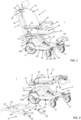
- the armchair 1 comprises a base 2 extending in a horizontal plane in the position of use of the chair, a seat 3 arranged in height relative to the base and in a plane parallel to it in the position of use, two pieces support and connection 4 ensuring the fixing of the seat 3 to the base 2, and a structure 5 for gripping and pushing the chair, called a gripping structure because it extends in a substantially vertical plane in the position of use of the chair, said structure of grip 5 being arranged behind the seat 3, and fixed to the base 2 and to the seat 3.
- the seat 3 is foldable and the gripping structure 5 is removable.
- the gripping structure 5 is removable relative to the base 2 and relative to the seat 3, so as to constitute an independent part.
- the seat 3 also being removable relative to the base 2, leading to an armchair made up of three independent parts which can be handled independently (which is less heavy) and store independently (providing freedom of arrangement).
- the gripping structure 5 has a general inverted U shape and comprises two uprights 50 and 51 and at least one upper end crosspiece or bar 52 connecting the two uprights at their upper end.
- the bar 52 serves as a gripping means for a third person who wishes to push the chair 1.
- the latter can include, as illustrated, two other crosspieces 53 and 54.
- the lower ends 55 of the uprights 50 and 51 are free and are intended to cooperate removably with the frame 20 of the base 2, as will be seen later.
- the bar 52 may include control means 52' of the motorization of the chair, which can be accessible to the third person to drive and move the chair.
- the upper end of the uprights 50 and 51, at a distance from the bar 52 is curved backwards which contributes to the rigidity of the gripping structure.
- the base 2 comprises a lower chassis 20 and rolling means 21 fixed to the chassis 20.
- the lower chassis 20 comprises a platform 22 which accommodates at the rear, without protruding from the chassis, a box 23 housing one or more batteries to power electrically the motorization.
- the motor is integrated in a known manner into the rolling means 21.
- the rolling means 21 are for example two large wheels at the rear and two small wheels at the front.
- the armchair 1 comprises a footrest 24 which is fixed to the lower frame 20 of the base 2.
- it is here retractable by adopting either an deployed position ( figure 1 ), or a stowed position ( Figure 3 And Figure 11 ) by integrating into the upper part of the platform 22 of the chassis 20, parallel to it.
- the footrest 24 in its stowed position is flat and does not take up the free space under the seat 3.
- the way in which it is retractable will be described later by way of non-limiting example.
- the footrest 24 In the deployed position, it can take several reclining positions.
- the footrest 24 is fixed at two opposite points making it stable and sturdy; it can thus also constitute a step stool.
- the seat 3 comprises a seat 30, a backrest 31, and preferably armrests 32.
- the seat 30 comprises a frame 33 and a padding 34.
- the backrest 31 comprises a frame 35 and a padding 36.
- the seat 3 is foldable. The backrest 31 folds parallel and against the seat 30 by articulation means 6.
- the motorized wheelchair of the invention can be arranged in a more compact manner when not in use as shown on the figure 2 .
- the articulation means 6 are designed to arrange the backrest 31 according to a choice of several angular positions. A preferred example of articulation means 6 will be described later.
- the armrests 32 may include at the front distal end 32' support means for accessories ( figure 1 ) such as telephone, remote control, etc.
- the seat 3 is carried by the base 2 thanks to two support and connection parts 4.
- the support and connection parts 4 are arranged in the rear part of the armchair 1 and are capable of carrying the seat 3 door-to-door. false so as to create a free volume under the entire seat.
- the free volume which is located above the platform 22 of the chassis 20 of the base is accessible not only from the front of the chair but especially advantageously at the level of the two lateral sides of the chair.
- the two support and connection parts 4 are integral with the seat 3 and are coupled to the base 2 in a removable manner.
- the seat 3 can also be dismantled relative to the base, so as to present the chair of the Figure 3 in three parts, making it even more compact.
- the two support and connection parts 4 are identical. They are spaced apart and secured to the seat 3. They are fixed to the frame 33 of the seat 30 at the level of the side edges 33' of the frame and in the rear end zone.
- the two support and connection parts 4 cooperate, on the one hand with the base 2, in particular with the chassis 20, and on the other hand, with the gripping structure 5.
- the support and connecting parts 4, the gripping structure 5, the chassis 20 of the base and the frame 33 of the seat are preferably made of plastic or composite material. Alternatively, they could be metallic.
- Each of the support and connection parts 4 comprises two parts, a support part 40 with a bracing or strut function (intended to connect the base to the seat) and a connection part 41 (intended to connect the support part for the gripping structure 5).
- each support and connection part 4 In the assembled position of the seat 3 to the base 2, each support and connection part 4 has a general V shape.
- each support and connection piece 4 forms with (a portion of) the gripping structure 5, a triangle of forces.
- Each triangle of force extends in a vertical and lateral plane of the chair while being arranged at the lower end of the gripping structure 5 and at the rear end of the base 2 and the seat 3.
- the support part 40 extends in a vertical plane starting from a lateral edge 20' and at the rear end 20A of the chassis 20, and joins the side edge 33' just above the frame 33 of the seat 30.
- the support part 40 is arranged inclined from the rear end 20A of the chassis 20 towards the front of the seat 3, the support part remaining arranged in a plane of the lateral edge of the seat and at the rear end of the seat.
- the inclination of the support part 40 is preferably approximately 45°.
- the connecting part 41 with the gripping structure 5 it cooperates with the gripping structure 5 at a height corresponding to the plane of the seat 30.
- the connecting part 41 extends parallel and against the lateral edge 33' in the corner area of seat 3 all protruding at the rear of the seat 30 to be able to cooperate with the gripping structure 5.
- the support part 40 has a cylindrical geometry, while the connecting part 41 has a flat elongated shape.
- the support part 40 is integral with the connecting part 41.
- the support part 40 has a free distal end 40A intended to mate with the frame 20 of the base 2.
- the connecting part 41 has a free distal end 41A intended to mate with the gripping structure 5.
- each V-shaped support and connection part 4 is articulated allows (when its two free ends 40A and 41A are uncoupled from the base 2 and the gripping structure 5) to fold back on itself. , allowing all the components of the seat 3 to be arranged in parallel planes, providing a seat that is completely folded on top of itself, making it easy to store.
- the seat 3 is foldable by the articulation means 6 connecting the seat 30 to the backrest 31 so that the backrest 31 folds parallel and against the seat 30.
- the articulation means 6 are designed to allow the backrest 31 to be arranged in several angular tilt positions for the user.
- the articulation means 6 comprise two opposite flanges 60 arranged on the two respective lateral sides of the seat, means 61 for adjusting the angular position of the backrest 31 relative to the seat 30, locking members 62 of the position angular on each of the lateral sides of the seat, and preferably an actuating member 63 for concomitantly actuating the locking members 62 on each side of the seat.
- the two flanges 60 are fixed to the side edges 33' of the frame 33 of the seat 30, in particular are fixed to the two connecting parts 41 of the two respective support and connecting parts 4.
- the fixing is made for example by screwing.
- the flanges 60 extend vertically and have in their upper part the means 61 for adjusting the angular position of the backrest 31 relative to the seat 30.
- each flange 60 comprise several spaced notches 61', extending in a vertical plane and of different angular orientation, while each locking member 62 consists of each lateral edge of the frame 34 of the backrest (to cooperate with each flange) into a key capable of being movable in vertical translation.
- the key 62 In the low position, the key 62 is housed in one of the notches 61' depending on the desired inclination position of the backrest ( figures 8A And 8B ), and in the high position, it is extended ( Figure 9 ) to be able to tilt folder 31 forward ( Figure 10 ) until folding it against the seat 30 ( figure 2 ).
- the actuating member 63 of the keys 62 located on each lateral side of the seat is an actuating bar which is transverse, located at the rear of the backrest 31 and which is connected by its ends to the keys 62.
- the seat 3 may include a headrest 64 ( figure 1 ) which can be adjustable in height and inclination.
- the footrest 24 comprises two connecting rods 240 on each side of the base 2 (at the front end and between the two 20' side edges of the base).
- Each link 240 can have an arcuate shape.
- each link 240 is made of perforated material to save weight.
- Each link 240 has a first articulation 241 at one of its ends, which is made integral with the chassis 20, and a second articulation 242 at its opposite end, which is made integral with the footrest 24.
- the second articulation 242 of the links 240 ensures the pivoting of the footrest 24 around a horizontal axis passing through said joints to allow the inclination of the footrest.
- the base 2 advantageously includes a handle 7 at the rear (under the housing 23 and between the rolling means 21) in order to facilitate the grip of the base 2 and its handling when it is disassembled from the seat 3 and the gripping structure 5.
- the base 2 can also include at the rear and between the rolling means 21 casters 8. These casters 8 make it possible to roll the base 2 vertically when it is uncoupled from the seat 3 and the gripping structure 5, so as to help its movement.
Landscapes
- Health & Medical Sciences (AREA)
- Life Sciences & Earth Sciences (AREA)
- Animal Behavior & Ethology (AREA)
- General Health & Medical Sciences (AREA)
- Public Health (AREA)
- Veterinary Medicine (AREA)
- Special Chairs (AREA)
- Chairs Characterized By Structure (AREA)
- Chairs For Special Purposes, Such As Reclining Chairs (AREA)
Applications Claiming Priority (1)
| Application Number | Priority Date | Filing Date | Title |
|---|---|---|---|
| FR2214228A FR3143972B1 (fr) | 2022-12-22 | 2022-12-22 | Fauteuil roulant motorise pliable et demontable |
Publications (1)
| Publication Number | Publication Date |
|---|---|
| EP4397291A1 true EP4397291A1 (de) | 2024-07-10 |
Family
ID=85461848
Family Applications (1)
| Application Number | Title | Priority Date | Filing Date |
|---|---|---|---|
| EP23219531.3A Pending EP4397291A1 (de) | 2022-12-22 | 2023-12-21 | Faltbarer und zerlegbarer motorisierter rollstuhl |
Country Status (2)
| Country | Link |
|---|---|
| EP (1) | EP4397291A1 (de) |
| FR (1) | FR3143972B1 (de) |
Citations (3)
| Publication number | Priority date | Publication date | Assignee | Title |
|---|---|---|---|---|
| EP0048717B1 (de) * | 1980-03-28 | 1986-01-08 | ENIX, Wilma | Zusammenklappbares angetriebenes vierradfahrzeug |
| FR2779636B1 (fr) * | 1998-06-15 | 2000-09-08 | Jean Paul Dudouyt | Support de fixation d'accessoires pour fauteuil roulant manuel |
| FR2860709A1 (fr) | 2003-10-10 | 2005-04-15 | Dupont Medical | Fauteuil roulant motorise. |
-
2022
- 2022-12-22 FR FR2214228A patent/FR3143972B1/fr active Active
-
2023
- 2023-12-21 EP EP23219531.3A patent/EP4397291A1/de active Pending
Patent Citations (3)
| Publication number | Priority date | Publication date | Assignee | Title |
|---|---|---|---|---|
| EP0048717B1 (de) * | 1980-03-28 | 1986-01-08 | ENIX, Wilma | Zusammenklappbares angetriebenes vierradfahrzeug |
| FR2779636B1 (fr) * | 1998-06-15 | 2000-09-08 | Jean Paul Dudouyt | Support de fixation d'accessoires pour fauteuil roulant manuel |
| FR2860709A1 (fr) | 2003-10-10 | 2005-04-15 | Dupont Medical | Fauteuil roulant motorise. |
Also Published As
| Publication number | Publication date |
|---|---|
| FR3143972A1 (fr) | 2024-06-28 |
| FR3143972B1 (fr) | 2024-11-15 |
Similar Documents
| Publication | Publication Date | Title |
|---|---|---|
| EP0296075A1 (de) | Zerlegbarer Stuhl | |
| FR3101290A1 (fr) | Siège de véhicule | |
| EP0561774A1 (de) | Faltbarer rollstuhl. | |
| EP4056241A1 (de) | Ausrüstung zum praktizieren von basketball | |
| EP2583653A1 (de) | Krankenbett mit entfernbarem Transportwagen | |
| EP1179449B1 (de) | Mittelkonsole, insbesondere für den Kraftfahrzeuginnenraum | |
| EP1214238B1 (de) | Zusammenklappbarer wagen | |
| EP0323781B1 (de) | Zusammenlegbares wasserdichtes kofferartiges Sitzmöbel für draussen | |
| EP1693275A2 (de) | Schirmartig zusammenklappbarer Kinderwagen | |
| EP4397291A1 (de) | Faltbarer und zerlegbarer motorisierter rollstuhl | |
| FR3047169A1 (fr) | Chaise | |
| EP2189355A2 (de) | Kinderwagengestell zum Zusammenklappen und entsprechender Kinderwagen | |
| EP1931295B1 (de) | Faltbares Rollstuhl-Fahrgestell und faltbarer Rollstuhl | |
| EP0052031A1 (de) | In beschränktem Volumen und beschränkter Länge klappbarer Stuhl | |
| EP3978333B1 (de) | Manuell bedienbarer förderwagen | |
| FR2621244A1 (fr) | Appareil elevateur pour personne handicapee | |
| FR3048401A1 (fr) | Poussette convertible, entretoise, support et procede correspondants | |
| EP1693276B1 (de) | Zusammenklappbarer Kinderwagen mit einer drehbaren Fussstütze | |
| FR2805866A1 (fr) | Systeme pour monter une structure telle qu'un plateau ou panneau sur une surface d'appui ou de fixation | |
| EP0291433A1 (de) | Klappstuhl | |
| EP0952277A1 (de) | Teleskopartige Arbeitsplatte | |
| FR2919835A1 (fr) | Module de rangement escamotable et amovible pouvant etre fixe dans un vehicule automobile | |
| EP0161157A1 (de) | In ein Bett umwandelbarer Sitz | |
| FR2794392A1 (fr) | Etabli pliant perfectionne | |
| EP0011546B1 (de) | Stapelbare Klappmöbel |
Legal Events
| Date | Code | Title | Description |
|---|---|---|---|
| PUAI | Public reference made under article 153(3) epc to a published international application that has entered the european phase |
Free format text: ORIGINAL CODE: 0009012 |
|
| STAA | Information on the status of an ep patent application or granted ep patent |
Free format text: STATUS: THE APPLICATION HAS BEEN PUBLISHED |
|
| AK | Designated contracting states |
Kind code of ref document: A1 Designated state(s): AL AT BE BG CH CY CZ DE DK EE ES FI FR GB GR HR HU IE IS IT LI LT LU LV MC ME MK MT NL NO PL PT RO RS SE SI SK SM TR |
|
| STAA | Information on the status of an ep patent application or granted ep patent |
Free format text: STATUS: REQUEST FOR EXAMINATION WAS MADE |
|
| 17P | Request for examination filed |
Effective date: 20250107 |