EP4400687A1 - Ferrure d'alignement pour l'alignement d'un vantail de porte ainsi que vantail et procédé d'assemblage d'une ferrure d'alignement associés - Google Patents
Ferrure d'alignement pour l'alignement d'un vantail de porte ainsi que vantail et procédé d'assemblage d'une ferrure d'alignement associés Download PDFInfo
- Publication number
- EP4400687A1 EP4400687A1 EP23151287.2A EP23151287A EP4400687A1 EP 4400687 A1 EP4400687 A1 EP 4400687A1 EP 23151287 A EP23151287 A EP 23151287A EP 4400687 A1 EP4400687 A1 EP 4400687A1
- Authority
- EP
- European Patent Office
- Prior art keywords
- screw
- rod
- sleeve
- channel
- door leaf
- Prior art date
- Legal status (The legal status is an assumption and is not a legal conclusion. Google has not performed a legal analysis and makes no representation as to the accuracy of the status listed.)
- Withdrawn
Links
Images


Classifications
-
- E—FIXED CONSTRUCTIONS
- E06—DOORS, WINDOWS, SHUTTERS, OR ROLLER BLINDS IN GENERAL; LADDERS
- E06B—FIXED OR MOVABLE CLOSURES FOR OPENINGS IN BUILDINGS, VEHICLES, FENCES OR LIKE ENCLOSURES IN GENERAL, e.g. DOORS, WINDOWS, BLINDS, GATES
- E06B3/00—Window sashes, door leaves, or like elements for closing wall or like openings; Layout of fixed or moving closures, e.g. windows in wall or like openings; Features of rigidly-mounted outer frames relating to the mounting of wing frames
- E06B3/96—Corner joints or edge joints for windows, doors, or the like frames or wings
- E06B3/964—Corner joints or edge joints for windows, doors, or the like frames or wings using separate connection pieces, e.g. T-connection pieces
- E06B3/9649—Tie rods spanning the whole width or height of the frame; Straps encircling the frame
Definitions
- the invention relates to an alignment fitting for aligning a door leaf and a door leaf with such an alignment fitting and also a method for assembling an alignment fitting.
- Alignment fittings for aligning a door leaf are known, e.g. ITMI982587A1 , ITMI20060337U1 and ITMI20070305U1 .
- the present invention is based on the object of specifying an alternative alignment fitting as well as a method for assembling such an alignment fitting that is as simple as possible.
- the internal thread of the screw channels, the first external thread of the rod and the external thread of the screw-in sleeve are each a first metric thread and the second external thread of the rod and the internal thread of the screw-in sleeve are each a second metric thread that is smaller than the first metric thread.
- two fine threads or a combination of a metric and a fine thread can be used instead.
- the thinner rod end and a middle rod section located between the two rod ends each have an outer diameter that is smaller than the inner diameter of the screw channels.
- the inner channel between the two screw channels has a middle channel section with an incircle whose inner diameter is larger than the outer diameter of the thinner rod end and a middle rod section.
- the hollow profile is preferably made of metal, in particular an aluminum extruded profile, and can have a rectangular, in particular square, outer cross-section.
- the rod can be in one piece or, as is preferred, can be formed by a threaded rod, one end of which forms the thinner rod end, and by a threaded sleeve screwed onto the other end of the threaded rod, which forms the thicker rod end and is connected to the threaded rod in a rotationally fixed and non-removable manner.
- the threaded sleeve can advantageously have the rotating handle, e.g. in the form of a polygon.
- the threaded rod can also advantageously be made up of several handy (e.g. 1m long) threaded rod pieces, which reduces the packaging size for the components of the erecting fitting accordingly.
- the hollow profile is integrated into a handle profile for the door leaf, i.e. formed as a single piece.
- the rod When the erecting fitting is assembled, the rod is screwed with its thicker rod end into a first of the two screw channels and with its thinner rod end into the screw-in sleeve screwed into the other, second screw channel and can be rotated by means of the rotating handle in order to generate either a compressive or a tensile stress in the rod and thus in the hollow profile due to the different thread pitches, depending on the direction of rotation of the rotating handle.
- the invention also relates to a door leaf, in particular a sliding or revolving door, with an alignment fitting as designed above, mounted on the door leaf in the longitudinal direction of the door, in order to produce a transverse deformation of the door leaf in one direction or the other at right angles to the front and rear of the door, depending on the direction of rotation of the rotary handle, and to counteract a bulging of the door leaf at the front or rear.
- the hollow profile can, for example, be mounted on a narrow side of the door leaf or in a longitudinal groove on the front or back of the door.
- the invention also relates to a method for assembling an alignment fitting designed as above with the method steps of claim 13.
- the screw-in sleeve is screwed into the second screw channel until it rests against the outside of the hollow profile with a collar.
- an internal thread can be cut into each of the two ends of the inner channel, in particular by means of a self-tapping screw, in order to form the screw channels.
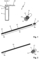
- the middle rod section 8c between the two rod ends 8a, 8b also has an external thread 15 corresponding to the second external thread 10 , here an M5 external thread, but can alternatively also be threadless.
- the thinner rod end 8b and the middle rod section 8c each have an outer diameter that is smaller than the inner diameter of the screw channels 6a, 6b.
- the inner channel 5 has a threadless middle section 5c ( Figs. 5b, 5c ) with an inscribed circle whose inner diameter is larger than the outer diameter of the thinner rod end 8b and the middle rod section 8c and can be smaller than the inner diameter of the screw channels 6a, 6b.
- the hollow profile 3 can, for example, have a rectangular, in particular square, outer profile cross-section.
- the rod 8 can be one-piece or, as in Fig.2 shown, in two parts by a threaded rod 16 , one end of which forms the thinner rod end 8b, and by a threaded sleeve 17 which is open on one side and is screwed onto the other end of the threaded rod 16 and is connected to the threaded rod 16 in a rotationally fixed and non-releasable manner.
- the threaded sleeve 17 forms the thicker rod end 8a with the M8 external thread 9 and with the M5 internal thread 14.
- the threaded sleeve 17 has the rotating handle 11 in the form of an internal polygon (e.g. internal hexagon SW4).
- the threaded rod 16 can in turn be composed of several threaded rod pieces, in particular screwed together.
- the rod 8 is cut to a predetermined length, e.g. to the length of the hollow profile 3 minus 25 mm.
- the M8 internal thread 7 of the two screw channels 6a, 6b is first cut into the inner channel 5 at the end using a cutting screw 18 , e.g. M8x40 cutting screw ( Figs. 3a-3c ).
- the rod 8 with the thinner rod end 8b first, is pushed through the first screw channel 6a into the inner channel 5 ( Fig. 4a ) and by rotating the rod 8 by means of a tool engaging the rotary handle 11 (e.g. Hexagon wrench SW4) 19 is turned, the thicker rod end 8a is screwed a certain amount, e.g. approx. 20 to 25mm, into the first screw channel 6a ( Figs. 4b, 4c ).
- a tool engaging the rotary handle 11 e.g. Hexagon wrench SW4
- a cylinder head screw (e.g. M5x12mm) 20 is screwed into the M5 internal thread 14 of the screw-in sleeve 12 until it rests against the screw-in sleeve 12 in order to form, together with the screw-in sleeve 12, a first screw connection 22 effective in the screwing direction 21 ( Fig. 5a ).
- the screw-in sleeve 12 is screwed into the second screw channel 6b on the one hand and screwed onto the thinner rod end 8b on the other hand until the cylinder head screw 20 rests on the rod 8 and the first screw connection 22 together with the rod 8 thus forms a second screw connection 23 that is effective in the screw-in direction 21.
- the cylinder head screw 20 forms a stop in the screw-in sleeve 12 that limits the screwing of the screw-in sleeve 12 onto the thinner rod end 8b, for example to about half the maximum possible screw-on length.
- the cylinder head screw 20 is unscrewed from the screw-in sleeve 12 ( Fig. 5c ) to remove the stop and thus to be able to screw the thinner rod end 8b further into the screw-in sleeve 12. From the zero position, the rod 8 can thus be rotated in both directions.
- the rod 8 is screwed with its thicker rod end 8a into the first screw channel 6a and with its thinner rod end 8b into the screw-in sleeve 12 screwed into the second screw channel 6b and can be rotated by means of the rotating handle 11.
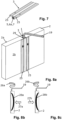
- Fig. 6a shows the handle bar profile screwed onto a narrow side of the sliding door 2 in the longitudinal direction of the door by means of a lateral profile leg 25 with the handle bar 4 and the hollow profile 3 in which the alignment fitting 1 is mounted.
- the turning handle 11 is located on the top of the sliding door 2.
- the rod 8 can be turned using a tool (e.g. hexagon key SW4) 19 that engages the turning handle 11. Due to the different M8 and M5 thread pitches on the thicker and thinner rod ends 8a, 8b, when the rod 8 is turned, depending on the direction of rotation 26a , 26b , either a compressive or a tensile stress is generated in the rod 8 and thus in the hollow profile 3.
- Fig. 8a shows the hollow profile 3 of the sliding door 2 inserted into a longitudinal groove 29 and screwed to the rear side 26 of the door by means of the two lateral profile legs 25.
- Fig.7 in which the alignment fitting 1 is mounted.
- a front or rear bulge 28a, 28b of the sliding door 2 can be counteracted and the sliding door 2 can thus be aligned.
Landscapes
- Engineering & Computer Science (AREA)
- Civil Engineering (AREA)
- Structural Engineering (AREA)
- Securing Of Glass Panes Or The Like (AREA)
- Bay Windows, Entrances, And Structural Adjustments Related Thereto (AREA)
Priority Applications (5)
| Application Number | Priority Date | Filing Date | Title |
|---|---|---|---|
| EP23151287.2A EP4400687A1 (fr) | 2023-01-12 | 2023-01-12 | Ferrure d'alignement pour l'alignement d'un vantail de porte ainsi que vantail et procédé d'assemblage d'une ferrure d'alignement associés |
| PCT/EP2024/050266 WO2024149699A1 (fr) | 2023-01-12 | 2024-01-08 | Raccord d'alignement pour aligner un battant de porte, battant de porte associé et procédé d'assemblage d'un raccord d'alignement |
| PL24700229.8T PL4558693T3 (pl) | 2023-01-12 | 2024-01-08 | Okucie wyrównawcze do wyrównywania skrzydła drzwiowego, jak i przynależne skrzydło drzwiowe i sposób montażu okucia wyrównawczego |
| EP24700229.8A EP4558693B1 (fr) | 2023-01-12 | 2024-01-08 | Ferrure d'alignement pour l'alignement d'un vantail de porte ainsi que vantail et procédé d'assemblage d'une ferrure d'alignement associés |
| ES24700229T ES3054062T3 (en) | 2023-01-12 | 2024-01-08 | Alignment fitting for aligning a door leaf and associated door leaf and method for assembling an alignment fitting |
Applications Claiming Priority (1)
| Application Number | Priority Date | Filing Date | Title |
|---|---|---|---|
| EP23151287.2A EP4400687A1 (fr) | 2023-01-12 | 2023-01-12 | Ferrure d'alignement pour l'alignement d'un vantail de porte ainsi que vantail et procédé d'assemblage d'une ferrure d'alignement associés |
Publications (1)
| Publication Number | Publication Date |
|---|---|
| EP4400687A1 true EP4400687A1 (fr) | 2024-07-17 |
Family
ID=84943085
Family Applications (2)
| Application Number | Title | Priority Date | Filing Date |
|---|---|---|---|
| EP23151287.2A Withdrawn EP4400687A1 (fr) | 2023-01-12 | 2023-01-12 | Ferrure d'alignement pour l'alignement d'un vantail de porte ainsi que vantail et procédé d'assemblage d'une ferrure d'alignement associés |
| EP24700229.8A Active EP4558693B1 (fr) | 2023-01-12 | 2024-01-08 | Ferrure d'alignement pour l'alignement d'un vantail de porte ainsi que vantail et procédé d'assemblage d'une ferrure d'alignement associés |
Family Applications After (1)
| Application Number | Title | Priority Date | Filing Date |
|---|---|---|---|
| EP24700229.8A Active EP4558693B1 (fr) | 2023-01-12 | 2024-01-08 | Ferrure d'alignement pour l'alignement d'un vantail de porte ainsi que vantail et procédé d'assemblage d'une ferrure d'alignement associés |
Country Status (4)
| Country | Link |
|---|---|
| EP (2) | EP4400687A1 (fr) |
| ES (1) | ES3054062T3 (fr) |
| PL (1) | PL4558693T3 (fr) |
| WO (1) | WO2024149699A1 (fr) |
Citations (2)
| Publication number | Priority date | Publication date | Assignee | Title |
|---|---|---|---|---|
| US2956314A (en) * | 1959-02-02 | 1960-10-18 | Rowe Mfg Company | Glass panels for overhead door |
| EP3406824A1 (fr) * | 2017-05-25 | 2018-11-28 | OTLAV SpA | Tirant et procédé de montage de celui-ci |
Family Cites Families (1)
| Publication number | Priority date | Publication date | Assignee | Title |
|---|---|---|---|---|
| US2706543A (en) * | 1950-07-25 | 1955-04-19 | H A Kammerer Inc | Construction for doors and like closures |
-
2023
- 2023-01-12 EP EP23151287.2A patent/EP4400687A1/fr not_active Withdrawn
-
2024
- 2024-01-08 EP EP24700229.8A patent/EP4558693B1/fr active Active
- 2024-01-08 PL PL24700229.8T patent/PL4558693T3/pl unknown
- 2024-01-08 WO PCT/EP2024/050266 patent/WO2024149699A1/fr not_active Ceased
- 2024-01-08 ES ES24700229T patent/ES3054062T3/es active Active
Patent Citations (2)
| Publication number | Priority date | Publication date | Assignee | Title |
|---|---|---|---|---|
| US2956314A (en) * | 1959-02-02 | 1960-10-18 | Rowe Mfg Company | Glass panels for overhead door |
| EP3406824A1 (fr) * | 2017-05-25 | 2018-11-28 | OTLAV SpA | Tirant et procédé de montage de celui-ci |
Also Published As
| Publication number | Publication date |
|---|---|
| ES3054062T3 (en) | 2026-01-29 |
| EP4558693B1 (fr) | 2025-10-29 |
| PL4558693T3 (pl) | 2026-03-23 |
| WO2024149699A1 (fr) | 2024-07-18 |
| EP4558693A1 (fr) | 2025-05-28 |
Similar Documents
| Publication | Publication Date | Title |
|---|---|---|
| EP2742199B1 (fr) | Système de fixation pour fixer une pièce sur une rainure d'une fenêtre, d'une porte ou analogue | |
| EP3025066A1 (fr) | Écrou à sertir en aveugle pour le raccordement de deux éléments | |
| WO2019007911A1 (fr) | Système de fixation | |
| DE102014000940A1 (de) | Schraube, Befestigungsanordnung und Verwendung einer Schraube | |
| EP2224143A1 (fr) | Ecrou, raccordement de vis, connexion de profilé, ainsi que procédé de fabrication d'un écrou | |
| DE3804291C2 (fr) | ||
| EP3110587A1 (fr) | Système de fixation destiné à une panne | |
| DE102008001381B3 (de) | Baueinheit | |
| EP0872619A2 (fr) | Elément d'ajustement | |
| EP4558693B1 (fr) | Ferrure d'alignement pour l'alignement d'un vantail de porte ainsi que vantail et procédé d'assemblage d'une ferrure d'alignement associés | |
| EP2787265B1 (fr) | Pièce de cornière d'angle | |
| DE3246180C1 (de) | Sicherungsblech zum Haltern einer Schraube | |
| EP0515845A2 (fr) | Assemblage d'une traverse avec un montant d'une fenêtre en matière plastique | |
| DE102008025348B4 (de) | Kugelgewindetrieb mit Anschlagelement | |
| EP3808927A1 (fr) | Agencement doté de cadre et d'un battant appliqué au cadre à l'aide de charnières | |
| DE10118150B4 (de) | Befestigungsvorrichtung | |
| DE3210262A1 (de) | Rahmenbefestigungsduebel | |
| DE20111793U1 (de) | Muffenverbindung für Betonstäbe | |
| EP3530965A1 (fr) | Agencement d'un corps creux et d'un élément de renforcement, procédé de fabrication dudit agencement ainsi qu'élément de renforcement | |
| DE102015119874A1 (de) | Befestigungsanordnung | |
| DE102024110187A1 (de) | Verbindungselement mit Räumabschnitt, Rohteil zur Herstellung dieses Verbindungselements und Schraubverbindung mit diesem Verbindungselement | |
| DE102006000767A1 (de) | Vorrichtung zum Blindmontieren | |
| DE102015219187A1 (de) | Verbindungsvorrichtung zum starren Verbinden eines ersten Rohres mit einem zweiten Rohr | |
| EP0516945A2 (fr) | Dispositif de renfort pour gaines d'air en tôle | |
| DE19527602A1 (de) | Vorrichtung zum Befestigen von Gegenständen |
Legal Events
| Date | Code | Title | Description |
|---|---|---|---|
| PUAI | Public reference made under article 153(3) epc to a published international application that has entered the european phase |
Free format text: ORIGINAL CODE: 0009012 |
|
| STAA | Information on the status of an ep patent application or granted ep patent |
Free format text: STATUS: REQUEST FOR EXAMINATION WAS MADE |
|
| 17P | Request for examination filed |
Effective date: 20230629 |
|
| AK | Designated contracting states |
Kind code of ref document: A1 Designated state(s): AL AT BE BG CH CY CZ DE DK EE ES FI FR GB GR HR HU IE IS IT LI LT LU LV MC ME MK MT NL NO PL PT RO RS SE SI SK SM TR |
|
| GRAP | Despatch of communication of intention to grant a patent |
Free format text: ORIGINAL CODE: EPIDOSNIGR1 |
|
| STAA | Information on the status of an ep patent application or granted ep patent |
Free format text: STATUS: GRANT OF PATENT IS INTENDED |
|
| INTG | Intention to grant announced |
Effective date: 20241028 |
|
| RIN1 | Information on inventor provided before grant (corrected) |
Inventor name: WALZ, RUEDIGER |
|
| STAA | Information on the status of an ep patent application or granted ep patent |
Free format text: STATUS: THE APPLICATION IS DEEMED TO BE WITHDRAWN |
|
| 18D | Application deemed to be withdrawn |
Effective date: 20250301 |