EP4403742A2 - Raccord fileté - Google Patents
Raccord fileté Download PDFInfo
- Publication number
- EP4403742A2 EP4403742A2 EP24151693.9A EP24151693A EP4403742A2 EP 4403742 A2 EP4403742 A2 EP 4403742A2 EP 24151693 A EP24151693 A EP 24151693A EP 4403742 A2 EP4403742 A2 EP 4403742A2
- Authority
- EP
- European Patent Office
- Prior art keywords
- thread
- section
- function
- threaded
- flank
- Prior art date
- Legal status (The legal status is an assumption and is not a legal conclusion. Google has not performed a legal analysis and makes no representation as to the accuracy of the status listed.)
- Pending
Links
Images

Classifications
-
- E—FIXED CONSTRUCTIONS
- E21—EARTH OR ROCK DRILLING; MINING
- E21B—EARTH OR ROCK DRILLING; OBTAINING OIL, GAS, WATER, SOLUBLE OR MELTABLE MATERIALS OR A SLURRY OF MINERALS FROM WELLS
- E21B17/00—Drilling rods or pipes; Flexible drill strings; Kellies; Drill collars; Sucker rods; Cables; Casings; Tubings
- E21B17/02—Couplings; joints
- E21B17/04—Couplings; joints between rod or the like and bit or between rod and rod or the like
- E21B17/042—Threaded
-
- E—FIXED CONSTRUCTIONS
- E21—EARTH OR ROCK DRILLING; MINING
- E21B—EARTH OR ROCK DRILLING; OBTAINING OIL, GAS, WATER, SOLUBLE OR MELTABLE MATERIALS OR A SLURRY OF MINERALS FROM WELLS
- E21B17/00—Drilling rods or pipes; Flexible drill strings; Kellies; Drill collars; Sucker rods; Cables; Casings; Tubings
- E21B17/02—Couplings; joints
- E21B17/03—Couplings; joints between drilling rod or pipe and drill motor or surface drive, e.g. between drilling rod and hammer
-
- F—MECHANICAL ENGINEERING; LIGHTING; HEATING; WEAPONS; BLASTING
- F16—ENGINEERING ELEMENTS AND UNITS; GENERAL MEASURES FOR PRODUCING AND MAINTAINING EFFECTIVE FUNCTIONING OF MACHINES OR INSTALLATIONS; THERMAL INSULATION IN GENERAL
- F16L—PIPES; JOINTS OR FITTINGS FOR PIPES; SUPPORTS FOR PIPES, CABLES OR PROTECTIVE TUBING; MEANS FOR THERMAL INSULATION IN GENERAL
- F16L15/00—Screw-threaded joints; Forms of screw-threads for such joints
- F16L15/001—Screw-threaded joints; Forms of screw-threads for such joints with conical threads
-
- F—MECHANICAL ENGINEERING; LIGHTING; HEATING; WEAPONS; BLASTING
- F16—ENGINEERING ELEMENTS AND UNITS; GENERAL MEASURES FOR PRODUCING AND MAINTAINING EFFECTIVE FUNCTIONING OF MACHINES OR INSTALLATIONS; THERMAL INSULATION IN GENERAL
- F16L—PIPES; JOINTS OR FITTINGS FOR PIPES; SUPPORTS FOR PIPES, CABLES OR PROTECTIVE TUBING; MEANS FOR THERMAL INSULATION IN GENERAL
- F16L15/00—Screw-threaded joints; Forms of screw-threads for such joints
- F16L15/06—Screw-threaded joints; Forms of screw-threads for such joints characterised by the shape of the screw-thread
-
- F—MECHANICAL ENGINEERING; LIGHTING; HEATING; WEAPONS; BLASTING
- F16—ENGINEERING ELEMENTS AND UNITS; GENERAL MEASURES FOR PRODUCING AND MAINTAINING EFFECTIVE FUNCTIONING OF MACHINES OR INSTALLATIONS; THERMAL INSULATION IN GENERAL
- F16L—PIPES; JOINTS OR FITTINGS FOR PIPES; SUPPORTS FOR PIPES, CABLES OR PROTECTIVE TUBING; MEANS FOR THERMAL INSULATION IN GENERAL
- F16L55/00—Devices or appurtenances for use in, or in connection with, pipes or pipe systems
- F16L55/16—Devices for covering leaks in pipes or hoses, e.g. hose-menders
- F16L55/162—Devices for covering leaks in pipes or hoses, e.g. hose-menders from inside the pipe
- F16L55/165—Devices for covering leaks in pipes or hoses, e.g. hose-menders from inside the pipe a pipe or flexible liner being inserted in the damaged section
- F16L55/1658—Devices for covering leaks in pipes or hoses, e.g. hose-menders from inside the pipe a pipe or flexible liner being inserted in the damaged section the old pipe being ruptured prior to insertion of a new pipe
Definitions
- the invention relates to a threaded plug, a threaded bushing, a use of a threaded plug, a use of a threaded bushing and a threaded connection with a threaded plug and a threaded bushing, wherein the described entities can be designed for an earth drilling device.
- earth drilling device refers to devices with which the drive power of a drive device is transmitted via a rod to a tool that is arranged on a rod, in particular at the end.
- This includes in particular earth drilling devices with which earth bores and in particular horizontal bores are made in the ground.
- the drive device usually transmits thrust or pressure forces via the rod to the tool designed as a drill head. It is also possible for a rotary movement to be imposed on the rod about its longitudinal axis by means of the earth drilling device.
- existing bores in the ground or old pipes that have already been laid can be widened or pulled out and, if necessary, a new pipe can be pulled in at the same time.
- the earth drilling devices are often designed in such a way that they can be used both for creating earth bores and for pulling work, i.e. for widening an existing bore or an old pipe or for pulling in a new pipe.
- This makes it possible to first create a pilot bore using the same earthmoving device, whereby a pilot drill head is pushed through the soil until it reaches a target excavation pit, and the pilot drill head is replaced in the target excavation pit by an expander head, whereby the The pilot bore is widened when the drill rod is pulled back. If necessary, a new pipe attached to the expanding head can be pulled into the widened borehole at the same time.
- the rods of such earthwork devices usually consist of a number of rod sections, which are gradually connected to one another in accordance with the drilling advance.
- the individual rod sections are connected via coupling elements, whereby in addition to plug-in couplings, as in DE 196 08 980 described, particularly screw connections are widespread.
- the main advantages of screw connections are the low costs associated with their production and the possibility of having the screwing carried out easily and automatically.
- a major disadvantage of screw connections, however, is that they often represent the greatest weak points of the rod, which is due to the relatively small diameter in the area of the threaded plug of the threaded connection and the geometrically high notch effect of the thread itself.
- API threads and round threads according to DIN 20 400 are also known. However, the service life of such thread forms has proven to be too short in the daily operation of earth drilling devices.
- DE 198 03 304 A1 discloses a threaded connection with which rod sections of a drill rod are to be connected, whereby the drill rod is to be used in particular for rotary percussion drilling.
- the main features of these threaded connections are the asymmetrical shape of the thread with different pitch angles of the load-bearing and non-load-bearing flanks in rotary percussion drilling operation, as well as the provision of a threadless insertion section.
- the non-load-bearing flanks are also to be circularly arc-shaped.
- the DE 198 03 304 A1 The known threaded connection has proven to be insufficiently robust in daily operation.
- Threaded connections for rods of earth drilling devices are known in which the thread root forms a section of an ellipse.
- the thread shapes disclosed in this publication can be both asymmetrical and symmetrical.
- the invention was therefore based on the object of creating a threaded connection which, in particular, facilitates the formation and release of the connection and whose service life is impaired as little as possible or not at all.
- the idea of only having to take into account a reduction in the notch effect and wanting to achieve a more homogeneous stress distribution was abandoned, which is why an elliptical shape was previously provided at the thread base. Due to the elliptical shape, the stress maxima occurred less in the thread base than in the area of the flanks. Previously, the perfect thread shape had been assumed to be a simple elliptical design, as this has a positive effect on the service life of the thread connection. In the field of rod sections for earth drilling devices in particular, the elliptical shape was retained. The considerations were based on the fact that there was usually no geometric notch in the area of the flanks and the notch effect in the thread base was thereby reduced.
- the invention is not only the thread base and an extension to the further flank course that are important, but also the design of the flank further away from the thread base.
- the invention is based on a section of the flank in which the a tangent applied to a respective point of the section has an angle to the cone on which the thread is applied that is greater than 45°.
- the invention extends or changes the design of at least one section of the flank to adapt the geometry of the flank itself, wherein according to the invention a section of the flank that comes into contact with the other screw element is considered in particular.
- the design of the flanks for a threaded plug and/or a threaded bushing was changed in such a way that the shape of an ellipse was deviated from.
- the section of the flank is curved and has a significant portion of the thread height in which the angle to a connecting line of adjacent thread roots and/or thread crests is greater than 45°. This makes it possible to obtain an efficient power transmission of the screw connection, wherein the advantageous properties of a shape that is curved at least in the section of the flank can be used. This function makes it possible to extend the shape to the thread root or close to the thread root in order to reduce stresses in the thread root.
- the shape of the thread root was extended to the flank in the direction of a thread crest
- the shape of the flank can be extended to the thread root.
- the shape provided for the flank also enables an improvement in reducing stresses in the thread root. Improved force transmission, improved sliding and/or a reduction in stresses in the thread root can be achieved, so that on the one hand damage to the thread due to shearing or deterioration of the thread guidance, which is colloquially referred to as cold welding of the thread, and/or a notch effect in the thread root can be counteracted.
- the operating forces and operating moments can be reliably absorbed and the screwing can be more successful, and on the other hand, a thread form that is easy to construct and whose manufacture or production can surprisingly be carried out without major difficulties can be used.
- the shape of the thread should be designed with a significant section in the thread height, the tangents of which in this area enclose an angle with a connecting line between adjacent thread roots or thread crests that is greater than 45°.
- the area with a "pitch" of greater than 45° has a height that is at least 0.3 times the thread height, where the pitch is an angle of the section of the function that a tangent at the point of the function encloses with a connecting line between adjacent thread roots or thread crests.
- the shape described makes it possible, for example, to have a greater pitch or angle over a longer area than, for example, with an ellipse, on the surfaces where the thread is located, particularly in the area with a pitch of more than 45°.
- the shape can also be easily planned during construction. An extension to the thread base against the background of an improvement or reduction of stresses in the thread base can be achieved due to the shape described, whereas an ellipse only allows for a smaller design option.
- the invention provides a threaded plug on an elongated body for a threaded connection with a threaded bushing, wherein the threaded plug has a conical external thread in which a section of a flank of the external thread can be represented as a section of a function which has a curvature, wherein the section of the function has an angle to a connecting line of adjacent thread roots or thread crests which is greater than 45° over at least a height of 0.3 times the thread height.
- cylindrical (internal or external) thread includes a design of the (internal or external) thread such that the thread roots and/or the thread crests of the threaded plug or threaded bushing define a jacket which has a conical shape. This allows the threaded plug to be screwed onto the threaded bushing quickly and easily, with both the threaded plug and the threaded bushing preferably having a conical thread.
- the angle that the casing, on which the thread roots and/or thread crests lie, forms with a line parallel to the longitudinal axis of the threaded plug or the threaded bushing can preferably be in the range between 2° and 15°, in particular 2° to 12°, in particular 3° and 12°, more preferably 3° to 10°, more preferably 3° to 8°, more preferably 3° and 7°.
- the shape of the thread is usually viewed in the sense of the description in a sectional view, in which the threaded plug or, analogously, the threaded bushing is cut by a cutting plane that intersects the longitudinal axis of the elongated body or that contains the longitudinal axis.
- This allows the view to be viewed in a two-dimensional view, so that the cone angle can result from a connecting line of the thread roots or the thread crests in the sectional view; it can be provided that the cone angle is given (locally) by a connecting line of adjacent thread roots or adjacent thread crests.
- flank of the thread essentially includes the area or section of the thread between the thread root and the adjacent thread crest and vice versa. Due to the curved design of the flank section, it may be provided that the allocation of the areas of the "thread root” and the “thread crest” are not necessarily reduced to one point, since the thread root and/or thread crest, for example, have a plateau or an area with a very low pitch.
- the terms “thread root” and “thread crest” are described in more detail below.
- section of a flank includes a partial area or section of the thread between a thread root and an adjacent thread crest and vice versa.
- section of a function includes a function curve or (function) graph over an argument or value range.
- section of a function covers a region of a curve described by means of a function, in particular a mathematical function.
- the term "function" includes a mapping or a relationship between two sets that assigns exactly one element of the other (second) set to each element of one (first) set.
- a height of the flank (y value or y axis) can be assigned to a length or a point on a longitudinal axis (x value or x axis), which can be, for example, the longitudinal axis of the elongated body or a straight line connecting the thread roots.
- the term "function” includes a unique assignment or relationship; only one element of the second set is assigned to an element of the first set, in particular not two elements. The unique assignment or relationship can be described or expressed using a mathematical function, in particular a calculation rule.
- the term "function" can be in contrast to a parameter representation or a shape that cannot be represented using a function.
- a circle cannot be represented as a function, so a circular section that can adjoin the section of the function for the flank is to be seen as a supplement to the section of the flank that can be represented as a function.
- the term "function" includes a configuration that is not circular.
- the invention has recognized that the description of the flank or the representation of the flank as a function is important and has thus moved away from the idea of designing a flank essentially as an ellipse(s) and/or circle(s), for example.
- the design of a flank can essentially be represented as a function that is neither a circle nor an ellipse.
- the term "function" takes into account the different design compared to a circle or several circles or an ellipse or several ellipses and/or mixed forms thereof. It is not excluded that the section of the flank that can be represented as a function is followed by a section that is designed as a circular section.
- an additional shape that may be present - for example in the form of a circular section - can indeed be present, but can essentially be arranged in the flank so that there is essentially no contact with the counter element when the screw connection is loaded.
- Describing a section or a region of a flank as a section of a function can create the advantage that gradients can be flexibly adjusted - especially unlike circles or ellipses.
- the section of the flank that can be represented as a function is the section that comes into contact with the counter element in the screwed state.
- the section of the flank that can be represented as a function has a significant proportion of the supporting flank in the case of the screw connection being loaded.
- the high proportion can be reflected in the fact that the function extends over a large area between the thread root and the thread crest (continuously); it can be provided that the function extends over a range of substantially 0.4 to substantially 0.9 times the length between the thread root and the adjacent thread crest, in particular over a range of substantially 0.5 to substantially 0.9 times the length between the thread root and the adjacent thread crest, in particular over a range of substantially 0.6 to substantially 0.9 times the length between the thread root and the adjacent thread crest, in particular over a range of substantially 0.65 to substantially 0.85 times the length between the thread root and the adjacent thread crest, in particular contiguously.
- thread root in the sense of the description can include the lowest point between two adjacent thread crests, from which in particular a flank can extend to one of the two adjacent thread crests. If the lowest point between two adjacent thread crests is described as being included in the thread root, the thread root in the sense of the description does not have to be reduced to a single point, in particular the lowest point between two thread crests. Rather, a thread root in the sense of the description can extend over an area that is extended in the direction of the longitudinal axis of the elongated body or the threaded plug or the threaded bushing and can include the lowest point between two adjacent thread crests.
- the thread root can be plateau-shaped or designed as a plateau, whereby a slight or slight curvature can be present.
- a point-shaped or almost point-shaped design of the thread root is not excluded; In particular, in the case of a point-like or almost point-like design, it can be provided that a shape for forming a flank is connected to the thread root designed in this way, which can be determined, for example, by the section of the function, a circle radius or other parameters. It can be provided that the thread root indicates the point at which a supporting and a non-supporting flank meet.
- thread crest may, in the sense of the description, include the highest point between two adjacent thread roots. If the highest point between two adjacent thread roots is considered to be included in the thread crest is referred to, the thread crest within the meaning of the description does not have to be reduced to a single point, in particular the highest point between two thread roots. Rather, a thread crest within the meaning of the description can extend over an area that is extended in the direction of the longitudinal axis of the elongated body or the threaded plug or the threaded bushing and can include the highest point between two adjacent thread roots.
- the thread crest can be plateau-shaped or designed as a plateau, whereby a slight or minor curvature can be present.
- a punctual or almost punctual design of the thread crest is not excluded; in particular in the case of a punctual or almost punctual design, it can be provided that a shape for forming a flank adjoins the thread crest designed in this way, which can be determined, for example, by the section of the function, a circle radius or other parameters. It can be provided that an area that can extend from a highest point to a turning point in the flank is counted as the thread crest. It can also be provided that a flank extends from the thread crest in a section of a circular shape, in particular a section of a circle with a radius, to the section of the function, so that the section of the circular shape, in particular the section of a circle with a radius, can directly adjoin the section of the function. It can be provided that the thread crest indicates the point at which a supporting and a non-supporting flank meet.
- an X-axis can be laid or positioned in such a way that the X-axis is essentially a connecting line of the thread roots. It is preferable to lay or position the X-axis in such a way that the X-axis essentially coincides with the longitudinal axis of the elongated body or runs parallel to it. In both cases, the design, manufacture and/or planning can be simplified. In the latter case, it is also not necessary to tilt a function about an axis, but the function can be used as such.
- the term "(thread) height" to describe the thread includes the specification of a distance or length in relation to a cutting plane for viewing the thread, which can contain the longitudinal axis of the elongated body.
- the (thread) height can result from a length or distance between the thread root and adjacent thread crests, whereby a cone on which the thread crests are arranged can be taken into account. It can be provided that, in order to determine the thread height, the perpendicular is dropped from a connecting line connecting the thread crests to the thread root or a connecting line between adjacent thread roots.
- a tangent at the respective point of the flank or function is considered when considering the angle that the flank or function has with the connecting line of adjacent thread roots or thread crests.
- the section of the function describes the flank over a large area in relation to the longitudinal axis of the elongated body or the threaded plug or threaded bushing. It can be provided that the flank essentially has the section of the function except for roundings, "additional pieces" and/or "connecting areas". The section of the function can form a significant part of the flank. It can be provided that an area adjoining the section of the function is designed to be as small as possible.
- the section of the function can extend into the thread root. It is possible for the section of the function to describe the thread root for the corresponding flank, to which in particular the further flank adjacent to the thread root can be connected.
- the part of the thread root of the flank to which the section of the function relates can be designed as the section of the function.
- a different shape can be provided for the adjacent flank with the same thread root; for example, the section of the function can be connected to the other shape in the thread root.
- the adjacent flank can be designed non-mirror-symmetrically to the flank with the section of the function. It can be provided that the section of the function can expand or extend from the area with an angle greater than 45° to the thread root.
- a section of the flank is designed as a section of a function, then in the sense of the description in a preferred embodiment this is understood to mean that the section of the flank has exactly the section of the function and no other shape. It can be provided that the thread between two adjacent thread crests can be composed of several sections of more than one function.
- the shape of the thread root and the thread crest can be formed by the section of the function, a further section of a further function or shape or several sections of further functions or shapes. It is possible that the thread root and/or thread crest have a shape, particularly directly adjacent to the section of the function, which is particularly determined by a mathematically describable shape, preferably a circular section, more preferably a circular section.
- the section of the function has an angle to a connecting line of adjacent thread roots or thread crests that is greater than 45° over a height of at least 0.35 times, in particular at least 0.4 times, in particular at least 0.45 times, in particular at least 0.5 times, in particular at least 0.55 times, in particular at least 0.6 times, in particular at least 0.65 times, in particular at least 0.7 times, in particular at least 0.75 times the thread height.
- the effect according to the invention can be varied, in particular increased, as a result.
- an angle of the section of the function is not greater than 75°, in particular not greater than 70°, in particular not greater than 65°.
- the section of the function can be restricted in such a way that the section of the function has an angle to a connecting line of adjacent thread roots or thread crests that is greater than 45° and less than 75°, in particular less than 70°, in particular less than 65°, over a height of at least 0.3 times, in particular at least 0.35 times, in particular at least 0.4 times, in particular at least 0.45 times, in particular at least 0.5 times, in particular at least 0.55 times, in particular at least 0.5 times, in particular at least 0.6 times, in particular at least 0.65 times, in particular at least 0.7 times, in particular at least 0.75 times the thread height.
- the section of the function can be designed to increase monotonically over the relative thread height under consideration.
- a derivative of the section of the function can be designed to increase monotonically over the relative thread height under consideration.
- the section of the function can be used to create a large range with regard to the thread height in which the angle changes over a maximum of 20°, in particular a maximum of 25°, in particular a maximum of 30°.
- a contact angle can be selected that can be varied or is varied by the function, but over a significant range the contact angle remains in a desired range. Design and handling can be improved.
- a length range of the section of the function which has an angle to a connecting line of adjacent thread roots or thread crests that is greater than 45°, extends over a length between the thread root and the thread crest that is 0.1 times the length between the thread root and the thread crest of the flank whose section can be represented by the section of the function. This allows not only a height of the described area to be taken into account, but also a length that can be varied accordingly, in particular increased.
- the length range of the section of the function which has an angle to a connecting line of adjacent thread roots or thread crests which is greater than 45° extends over a length between thread root and thread crest which is 0.15 times, in particular 0.2 times, in particular 0.25 times, the length between thread root and thread crest of the flank whose section can be represented by the section of the function.
- the angle can vary up to a maximum of 75°, in particular a maximum of 70°, in particular a maximum of 65°, in particular a maximum of 60°, wherein an aforementioned embodiment can be provided with regard to a monotonically increasing course of the section of the function and a monotonically increasing course of the derivative of the section of the function.
- the term “length range” includes a range that extends in the direction of or along a longitudinal axis of the elongated body, the threaded plug or the threaded bushing, or in particular along a connecting line of adjacent thread roots or thread crests. If a longitudinal axis or connecting line is described with regard to the length range, the term “in the direction of” or “along” refers to a direction essentially parallel to the longitudinal axis or the connecting line.
- the thread crest can be positioned or arranged or defined on or at the plateau in order to determine a length in such a way that the thread crest is a point on the flank that describes the edge of the plateau (the first point that is at the level of the plateau).
- the choice of the length of the plateau can be advantageous.
- the section of the function extends in a region around the center of the thread height that is at least 0.2 times the thread height, wherein the region is designed such that the angle of the section of the function in the region to a connecting line of adjacent thread roots or thread crests changes by less than 20°, in particular 15°.
- the aforementioned region can be at least 0.25 times, in particular 0.3 times, in particular 0.35 times, in particular 0.4 times, in particular 0.45 times, in particular 0.5 times, in particular 0.55 times, in particular 0.6 times the thread height.
- the middle is determined and it is seen how far the section of the function extends from the middle to both the thread root and the thread tip in relation to the thread height.
- the smaller extent of the extension of Center to thread crest or center to thread root is multiplied by two.
- the selected consideration can take into account an asymmetrical arrangement of the flank section.
- the height of the section that adjoins the function to the thread root can be significantly smaller - or not present at all - than the height of the section that can adjoin in the direction of the thread crest.
- the angle can vary up to a maximum of 75°, in particular a maximum of 70°, in particular a maximum of 65°, wherein an aforementioned configuration can be provided with regard to a monotonically increasing course of the section of the function and a monotonically increasing course of the derivative of the section of the function.
- the information on the extension of the section of the flank which can be described by means of the function, supplements each other in such a way that the function extends over a length range and a thread height, so that a ratio of extension over thread height and extension over length range results, which is in the range from 1 to 4.
- a synergistic effect can be present in that the extension ratio is correlated with the angle that is achieved with the function for contact formation.
- a ratio of extension over thread height and extension over length range can be selected which is in particular in the range of 1 to 4, more preferably 1.2 to 4, more preferably 1.3 to 3.9, more preferably 1.3 to 3.8, more preferably 1.3 to 3.7, more preferably 1.3 to 3.6, more preferably 1.3 to 3.5, more preferably 1.3 to 3.4, more preferably 1.3 to 3.3, more preferably 1.3 to 3.2, more preferably 1.3 to 3.1, more preferably 1.3 to 3.0, more preferably 1.3 to 2.9, more preferably 1.3 to 2.8, more preferably 1.3 to 2.7, more preferably 1.3 to 2.6, more preferably 1.3 to 2.5, more preferably 1.3 to 2.4, more preferably 1.3 to 2.3, more preferably 1.3 to 2.2, more preferably 1.3 to 2.1, more preferably 1.3 to 2.0, more preferably 1.4 to 2.0, more preferably 1.5 to 2.0. It can be provided that the ratio 1.0 is correlated with 45°, the ratio 4.0 with 75°, the ratio 1.5 with
- the flank extends over a length from the thread root in the direction of a thread crest over a region in which the angle to a connecting line of adjacent thread roots or thread crests is less than 20°, which is greater than 0.1 times, in particular 0.15 times, in particular 0.2 times, in particular 0.25 times, in particular 0.3 times, in particular 0.35 times, in particular 0.4 times, the length between the thread root and thread crest of the flank, the section of which can be represented by the section of the function.
- This allows the core idea of the invention to be improved or even further be strengthened by counteracting the notch effect at the thread root. A synergistic effect can result.
- the section of the function extends into the area of the thread root, in particular into the thread root, whereby the function can embody the properties described in the description. This can result in a synergistic effect that the described properties can be realized with the function, which can enable good planning or construction and good manufacturability.
- the curvature is curved inwards, whereby the inward curvature previously designed for the elliptical shape can be retained conceptually.
- inwardly curved or “inwardly curved” or “convex” is to be understood as meaning a configuration in which the shape is such that the shape lies below one or each line of connection between two points of the shape.
- the flank in a preferred embodiment, has the section of the function and a further shape that connects the section of the flank with the thread crest. This allows a certain degree of variability to be achieved. It can be provided that the flank can have other, different areas or shapes in addition to the section of the function. It can be provided that the flank has or consists of exactly one section of the function and exactly one further shape. Simple planning and construction are possible in addition to good manufacturability.
- the section of the function is continuous. This can counteract a notch effect.
- the continuous course also enables a simple design with good production.
- the section of the function is a section of a hyperbolic function.
- the hyperbolic function can be rotated by approximately 45°, in particular 45° reduced by the cone angle.
- the function is a power function with an exponent less than 1 and a base with a power argument.
- Such functions are well known in this field despite a surprising use and can be varied within a certain range in such a way that very good results can be achieved.
- the exponent is in the range from 0.2 to 0.7, in particular from 0.3 to 0.6, and/or the base that is raised to a power has a term in which the argument is raised to a power that is in the range between 2.5 and 5.8, in particular between 2.7 and 5.6, in particular between 2.9 and 5.4.
- the flanks of the thread can be divided into load-bearing flanks and non-load-bearing flanks.
- the load-bearing flanks are responsible for the transmission of force from the threaded plug to the threaded bushing.
- a load-bearing flank is immediately adjacent to a non-load-bearing flank, i.e. a load-bearing and an adjacent, non-load-bearing flank are connected to one another by means of exactly one thread root or one thread crest arranged between them.
- the flank is a supporting flank. It can be made possible to distinguish between a supporting flank and a non-supporting flank, whereby a design that supports the core idea of the invention can be further improved. In particular, a different design can be selected for the supporting flank than for the non-supporting flank.
- a threaded plug can be created on an elongated body for a threaded connection with a threaded bush.
- the threaded plug has a conical external thread and can be designed as above, but it can also be considered particularly preferably an initially independent design, wherein a non-supporting flank of the thread has a section of a function that extends over a range is curved outwards around the middle between the thread root and the thread crest. It was recognized that a non-load-bearing flank can meet other requirements and thus a non-symmetrical design of the thread can be provided, in which in particular the non-load-bearing flank of the thread of the threaded plug can have an outwardly curved area.
- an outwardly curved area represents a departure from the usual shape, since an inwardly curved shape was previously intended.
- the function of the portion of the function for the non-bearing flank has a logarithm.
- a function having a logarithm is understood to be a function that has a logarithmic course or a section of a logarithmic spiral.
- the section of the function for the non-load-bearing flank extends over a height of at least 0.35 times, in particular at least 0.4 times, in particular at least 0.45 times, in particular at least 0.5 times, in particular at least 0.55 times, in particular at least 0.6 times, in particular at least 0.65 times, in particular at least 0.7 times, the thread height, whereby the design, the manufacturability and/or the use can be improved.
- the advantageous property can extend over a large range of the thread height.
- a length range of the section of the function for the non-load-bearing flank extends over a length between the thread root and the thread crest, which is 0.2 times the length between the thread root and the thread crest of the flank, the section of which can be represented by the section of the function of the non-load-bearing flank. This allows not only a height of the described area to be taken into account, but also a length that can be varied accordingly, in particular increased.
- the length range of the section of the function of the non-load-bearing flank can extend over a length between the thread root and the thread crest which is 0.25 times, in particular 0.3 times, in particular 0.35 times, in particular 0.4 times, in particular 0.45 times, the length between the thread root and the thread crest of the non-load-bearing flank.
- the section of the function of the non-load-bearing flank extends in a region around the middle in the thread height, which is at least 0.25 times the thread height.
- the aforementioned region can be at least 0.3 times, in particular 0.35 times, in particular 0.4 times, in particular 0.45 times, in particular 0.5 times, the thread height.
- a "function that has a logarithm” is understood to mean a function in which the argument, which can be part of a term, is logarithmized.
- a logarithm with any base is possible, as is a decimal or natural logarithm.
- the section of the function of the non-load-bearing flank begins at a distance from the thread root and the distance between the thread root and the beginning of the section of the function is bridged by means of an arc-shaped, in particular a circular arc-shaped, section, which is most preferably a circular arc.
- the non-load-bearing flank of the thread root has a circular arc-shaped section, in particular a circular arc segment, to which the section of the function is connected.
- the section of the function for the non-load-bearing flank is followed by a circular arc-shaped section, in particular a circular arc segment, which extends to the thread crest.
- the non-load-bearing flank can be represented or described by means of the section of the function, a circular arc-shaped section, in particular a circular arc segment, which extends from the section of the function to the thread root, and a circular arc-shaped section, in particular a circular arc segment, which extends from the section of the function to the thread crest.
- a thread between two adjacent thread roots or two adjacent thread crests can have a supporting flank as described in the description and a non-supporting flank as described in the description. This can result in a synergistic effect.
- the elongated body is a rod section of a drill string for an earth drilling device or a drive element for a rod section of a drill string of an earth drilling device.
- rod section in the sense of the description includes individual, in particular rigid, rod sections that can be connected to one another directly or indirectly and that can be connected to one another in the longitudinal axial direction to form a drill rod or a drill string.
- the rod sections can be used to connect be screwed together with the mechanical interposition of an intermediate element or without the interposition of an intermediate element using a threaded bushing with a threaded plug as described.
- a rod section does not necessarily have to have an element for screwing at both longitudinal ends, so that it is possible for the rod section to have i) a threaded bushing at one longitudinal end and a threaded plug at the other longitudinal end, ii) a threaded bushing at each of the longitudinal ends, iii) a threaded bushing at one longitudinal end and a different type of coupling element at the other longitudinal end.
- drill string in the sense of the description includes several interconnected rod sections.
- a bore can be drilled using a drill string, which can have a drill head at its front end and, if present, a drill head tip that can be designed as a drilling tool (for example, as an expander head).
- earth drilling device in the sense of the description includes a (and thus any) device which can move in particular a drill string with rod sections in an existing channel or a channel to be created, in particular in the ground, in order to create or widen a bore, in particular a horizontal bore (HD), or to pull pipelines or other long bodies into the ground.
- the earth drilling device can in particular be an HD device.
- An earth drilling device can be a device that drives a drill string and can in particular work by displacing soil.
- the drill string can be introduced into the ground in a translatory and/or rotary manner in the longitudinal axial direction of the drill string.
- the drill string can be moved in the ground by applying tension or pressure and, if necessary, also in a rotary or rotating manner.
- driver element in the sense of the description includes an element arranged on the earth drilling device, which is designed to be connected to a drill string or a rod section of the drill string in order to exert a translational and/or rotational force on the drill string.
- a rod section to be connected to the drill string is brought into engagement with the drive element in order to then connect the rod section connected to the drive element to the already drilled drill string.
- the invention also provides a threaded bushing on an elongated body for a threaded connection with a threaded plug, wherein the threaded bushing has a conical internal thread, in which a portion of a flank of the internal thread can be represented as a portion of a function which has a curvature, wherein the section of the function has an angle to a connecting line of adjacent thread roots or thread crests that is greater than 45° over a height of at least 0.2 times the thread height.
- a threaded bushing that is complementary to the threaded plug can be created.
- threaded plug preferred embodiments for the threaded bushing are possible with regard to the design of the shape, in particular a complementary design or a design of the thread corresponding to the threaded plug with similar advantages.
- the invention also provides, in an independent aspect relating to a patent-founding invention, a threaded bushing which is designed for a threaded connection with a threaded plug.
- the threaded bushing can have the properties described above, but can also be designed independently of the threaded bushing mentioned above.
- a non-load-bearing flank of the internal thread has a section of a function which is curved inwards over an area around the middle between the thread root and the thread crest.
- threaded bushing which relates to an aspect that independently justifies patentability
- preferred embodiments for the threaded bushing are possible with regard to the design of the shape, in particular a complementary design or a design of the thread corresponding to the threaded plug with similar advantages.
- the invention also provides a threaded connection which has a threaded plug as described in the description and a threaded bushing as described in the description.
- the invention also provides a use of a threaded plug or a threaded bushing described in the description for a threaded connection with a threaded bushing or a threaded plug.
- the threaded plug has an external thread or the threaded bushing has an internal thread, in which a section of a flank of the external thread or the internal thread can be represented as a section of a function that has a curvature, wherein the section of the function has an angle to a connecting line of adjacent thread roots or thread crests that is greater than 45° over a height of at least 0.2 times the thread height.
- the threaded bushing can be braced against a shoulder on the threaded plug.
- the threaded plug and threaded bushing can be brought into contact with each other with their end faces, so that a force screw connection is made between an end face of the shoulder and the supporting flanks, in particular those in the area near the shoulder.
- the shoulder or the end face on the threaded plug can alternatively or additionally serve as a maximum stop for the screw connection.
- Axial forces and/or torsional moments can also be transmitted by means of the shoulder or the end face(s).
- the end face angle of the end faces of the threaded plug and the threaded bushing, which can come into contact with each other is in the range of 65° to 90°, in particular in the range of 65° to 80°.
- the descriptions of the individual embodiments or aspects complement each other.
- the statements regarding the threaded plug can also apply to the threaded bushing and vice versa.
- the statements regarding the threaded plug and/or threaded bushing can also apply to the aspect of a "use”.
- the statements regarding the geometry of the thread, the elongated body connected to it, a rod section and the like also apply to the aspect of a threaded connection in which a described threaded plug is present in addition to the described threaded bushing.
- a threaded plug which is designed as described in the description, can also interact with a threaded bushing to a certain extent if the threaded bushing is not designed to be complementary or corresponding to the threaded plug.
- a mutually corresponding or complementary design of the threaded plug and the threaded bushing can be preferred.
- the thread pitch of the threaded bushing and/or the threaded plug is between 5 mm and 9 mm, preferably 7 mm.
- the cutting angle is between 20° and 30°.
- the cutting dimension of the threaded plug is at least 0.5 mm.
- the cutting dimension of the threaded bushing is at least 1 mm.
- the difference between the length of the threaded plug and the threaded bushing is at most 0.5 mm.
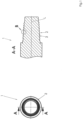
- Figure 1 shows in the right of the two representations a section of an elongated body 1 with a threaded plug 2 with an external thread 3 in a sectional view.
- the threaded plug 2 is located at the end of the elongated body 1, which is designed as a rod section of a drill string for an earth drilling device or a drive element for a rod section of a drill string of an earth drilling device.
- the right of the two representations of the Figure 1 is a sectional view of the left representation of the Figure 1 along AA.
- the left of the two representations of the Figure 1 shows a view of the threaded plug 2 of the elongated body 1 in the longitudinal direction of the elongated body 1.
- the elongated body 1 has a longitudinal axis L.
- the external thread 3 of the threaded plug 2 is a conical external thread.
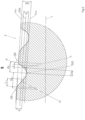
- the external thread 3 of the threaded plug 2 is shown in an enlarged view in the Figure 2 shown.
- Figure 2 shows the external thread 3 with the sizes applicable to the example.
- thread roots GG and thread crests GS are marked.
- the thread roots GG are located on a connecting line V GG of adjacent thread roots GG.
- the thread crests GS are located on a connecting line V GS of adjacent thread crests GS.
- connecting line V GG is parallel to connecting line Vos.
- the thread height is designated GH and indicates the length or distance between thread root GG and thread crest GS.
- a thread has a supporting flank and a non-supporting flank.
- the supporting flank extends from the thread root GG to the adjacent thread crest GS and is shown in the Figure 2 to the right of the thread root GG.
- the non-load-bearing flank extends to the left from the thread root GG to the adjacent thread crest GS.
- the supporting flank has a section that can be represented by a function ft.
- the function ft has a curvature.
- the section of the function f t has an angle to the connecting line V GG or V GS of adjacent thread roots GG or thread crests GS that is greater than 45° over a height H t of at least 0.3 times the thread height GH.
- a length range L t of the section of the function f t in which the function ft has an angle to the connecting line V GG or V GS of adjacent thread roots GG or thread crests GS that is greater than 45° is specified.
- the length range or the length L t extends over at least 0.1 times the length between the thread root GG and thread crest GS of the supporting flank.
- the section of the function f t extends in a region around the center GM in the thread height GH, which has at least 0.3 times the thread height GH, wherein the region is designed such that the angle of the section of the function ft in the region to a connecting line of adjacent thread roots GG or thread crests GS changes by less than 30°.
- the flank extends from the thread root GG over a length L GG in the direction of a thread crest GS, in which the angle to a connecting line of adjacent thread roots GG or thread crests GS is less than 20°, and the length L GG is greater than 0.1 times the length GL t between the thread root GG and the thread crest GS of the supporting flank, the section of which is represented by the section of the function ft.
- the function f t extends from the thread root GG to the right edge of the length designated L t .
- the function f t is followed by another form F t , which in the illustrated embodiment is a circular arc-shaped segment.
- the supporting flank is thus composed of the section of the function ft and a circular arc-shaped segment Ft between the function f t and the thread crest GS.
- the non-load-bearing flank is made up of three shapes.
- the first shape is a circular arc-shaped segment that extends from the thread root GG to the left to the right edge of the area L nt .
- the circular arc-shaped segment is followed by an area that is represented by a function f nt .
- the height over which the function f nt extends is specified as H nt .
- the section is designed as a function with an outward curvature.
- the function f nt is followed by a circular arc-shaped segment up to the thread tip GS.
- a thread of the embodiment shown in the figures for the threaded plug 2 comprises not only the supporting flank and the non-supporting flank but also at least partially the plateau at the level of the connecting line Vos.
- the thread of the Figure 2 which is marked with the designations for the sizes, comprise a plateau following one of the two thread crests GS up to the next adjacent thread crest GS.
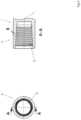
- Figure 3 shows in the right of the two representations a section of an elongated body 1 with a threaded bushing 4 with an internal thread 5.
- the threaded bushing 4 is located at the end of the elongated body 1, which is designed as a rod section of a drill string for an earth drilling device or a drive element for a rod section of a drill string of an earth drilling device.
- the right of the two representations of the Figure 3 is a sectional view of the left representation of the Figure 1 along AA.
- the left of the two representations of the Figure 3 shows a view of the threaded bushing 4 of the elongated body 1 in the longitudinal direction of the elongated body 1.
- the elongated body 1 has a longitudinal axis L.
- the internal thread 5 of the threaded bushing 4 is a conical internal thread.
- the internal thread 5 of the threaded bushing 4 is shown in an enlarged view in the Figure 4 shown.
- Figure 4 shows enlarged the internal thread 5, which is complementary to the external thread 3 of the threaded plug 2.
- the Figure 4 The sizes given correspond essentially to the sizes of the Figure 2 .
Landscapes
- Engineering & Computer Science (AREA)
- Geology (AREA)
- Life Sciences & Earth Sciences (AREA)
- Mining & Mineral Resources (AREA)
- Physics & Mathematics (AREA)
- Environmental & Geological Engineering (AREA)
- Fluid Mechanics (AREA)
- Mechanical Engineering (AREA)
- General Life Sciences & Earth Sciences (AREA)
- Geochemistry & Mineralogy (AREA)
- Prostheses (AREA)
- Earth Drilling (AREA)
- Non-Disconnectible Joints And Screw-Threaded Joints (AREA)
Applications Claiming Priority (1)
| Application Number | Priority Date | Filing Date | Title |
|---|---|---|---|
| EP23152005.7A EP4403741A1 (fr) | 2023-01-17 | 2023-01-17 | Raccord fileté |
Publications (2)
| Publication Number | Publication Date |
|---|---|
| EP4403742A2 true EP4403742A2 (fr) | 2024-07-24 |
| EP4403742A3 EP4403742A3 (fr) | 2024-09-04 |
Family
ID=84981922
Family Applications (2)
| Application Number | Title | Priority Date | Filing Date |
|---|---|---|---|
| EP23152005.7A Pending EP4403741A1 (fr) | 2023-01-17 | 2023-01-17 | Raccord fileté |
| EP24151693.9A Pending EP4403742A3 (fr) | 2023-01-17 | 2024-01-12 | Raccord fileté |
Family Applications Before (1)
| Application Number | Title | Priority Date | Filing Date |
|---|---|---|---|
| EP23152005.7A Pending EP4403741A1 (fr) | 2023-01-17 | 2023-01-17 | Raccord fileté |
Country Status (3)
| Country | Link |
|---|---|
| US (2) | US12534962B2 (fr) |
| EP (2) | EP4403741A1 (fr) |
| AU (1) | AU2024200255A1 (fr) |
Citations (6)
| Publication number | Priority date | Publication date | Assignee | Title |
|---|---|---|---|---|
| US5060740A (en) | 1990-05-29 | 1991-10-29 | Sandvik Rock Tools, Inc. | Screw thread coupling |
| EP0324442B1 (fr) | 1988-01-11 | 1992-03-18 | Sandvik Rock Tools Inc. | Profil de filet elliptique |
| DE19608980A1 (de) | 1996-03-08 | 1997-09-11 | Tracto Technik | Vorrichtung zum Bohren im Erdreich |
| DE19803304A1 (de) | 1997-05-29 | 1998-12-03 | Boart Hwf Gmbh Co Kg | Bohrgestänge zum Drehschlagbohren, insbesondere zum Überlagerungsbohren |
| WO2006092649A1 (fr) | 2005-03-02 | 2006-09-08 | Vallourec Mannesmann Oil & Gas France | Raccordement de masse-tige |
| EP2334892B1 (fr) | 2008-09-12 | 2017-02-22 | TRACTO-TECHNIK GmbH & Co. KG | Raccordement fileté |
Family Cites Families (14)
| Publication number | Priority date | Publication date | Assignee | Title |
|---|---|---|---|---|
| US2909380A (en) * | 1958-04-16 | 1959-10-20 | Edwin C Hoye | Threaded joint for tubular products |
| US3794092A (en) * | 1970-11-23 | 1974-02-26 | Textron Inc | Locking fastener |
| JPS56143889A (en) * | 1980-04-12 | 1981-11-09 | Nippon Steel Corp | Screw joint for high airtightness oil pipe |
| US4892337A (en) * | 1988-06-16 | 1990-01-09 | Exxon Production Research Company | Fatigue-resistant threaded connector |
| US6485063B1 (en) * | 1996-05-15 | 2002-11-26 | Huey P. Olivier | Connection |
| FR2820806B1 (fr) * | 2001-02-09 | 2004-02-20 | Vallourec Mannesmann Oil & Gas | Joint filete tubulaire avec face de filet bombee convexe |
| US7210710B2 (en) * | 2004-03-01 | 2007-05-01 | Omsco, Inc. | Drill stem connection |
| FR2969738B1 (fr) * | 2010-12-28 | 2016-03-25 | Vallourec Mannesmann Oil & Gas | Joint filete pour le forage et l'exploitation des puits d'hydrocarbures |
| AU2014296144A1 (en) * | 2013-07-31 | 2016-02-04 | Future Pipe Industries Group Limited | 4-round thread form |
| US10041307B2 (en) * | 2015-01-22 | 2018-08-07 | National Oilwell Varco, L.P. | Balanced thread form, tubulars employing the same, and methods relating thereto |
| US11125361B2 (en) * | 2018-03-01 | 2021-09-21 | Mitchell Z. Dziekonski | Thread form and threaded article |
| CN108252660A (zh) * | 2018-03-07 | 2018-07-06 | 上海海隆石油管材研究所 | 一种高扭矩高抗疲劳型螺纹接头 |
| CN108756771A (zh) * | 2018-08-02 | 2018-11-06 | 上海海隆石油管材研究所 | 一种管柱螺纹连接结构 |
| CN109882088B (zh) * | 2019-03-20 | 2022-02-18 | 上海海隆石油钻具有限公司 | 一种油井管柱连接接头 |
-
2023
- 2023-01-17 EP EP23152005.7A patent/EP4403741A1/fr active Pending
-
2024
- 2024-01-12 EP EP24151693.9A patent/EP4403742A3/fr active Pending
- 2024-01-15 AU AU2024200255A patent/AU2024200255A1/en active Pending
- 2024-01-16 US US18/413,212 patent/US12534962B2/en active Active
-
2025
- 2025-12-19 US US19/427,206 patent/US20260117604A1/en active Pending
Patent Citations (6)
| Publication number | Priority date | Publication date | Assignee | Title |
|---|---|---|---|---|
| EP0324442B1 (fr) | 1988-01-11 | 1992-03-18 | Sandvik Rock Tools Inc. | Profil de filet elliptique |
| US5060740A (en) | 1990-05-29 | 1991-10-29 | Sandvik Rock Tools, Inc. | Screw thread coupling |
| DE19608980A1 (de) | 1996-03-08 | 1997-09-11 | Tracto Technik | Vorrichtung zum Bohren im Erdreich |
| DE19803304A1 (de) | 1997-05-29 | 1998-12-03 | Boart Hwf Gmbh Co Kg | Bohrgestänge zum Drehschlagbohren, insbesondere zum Überlagerungsbohren |
| WO2006092649A1 (fr) | 2005-03-02 | 2006-09-08 | Vallourec Mannesmann Oil & Gas France | Raccordement de masse-tige |
| EP2334892B1 (fr) | 2008-09-12 | 2017-02-22 | TRACTO-TECHNIK GmbH & Co. KG | Raccordement fileté |
Also Published As
| Publication number | Publication date |
|---|---|
| AU2024200255A1 (en) | 2024-08-15 |
| EP4403741A1 (fr) | 2024-07-24 |
| US20260117604A1 (en) | 2026-04-30 |
| US20240384605A1 (en) | 2024-11-21 |
| EP4403742A3 (fr) | 2024-09-04 |
| US12534962B2 (en) | 2026-01-27 |
Similar Documents
| Publication | Publication Date | Title |
|---|---|---|
| DE69413011T2 (de) | Rohrverbindung mit nicht-schwalbenschwanzförmigen ineinandergreifenden keilförmigen gewindegängen | |
| DE60023504T2 (de) | Schraubverbindung für rohre | |
| DE102008047060B4 (de) | Gewindeverbindung | |
| DE69933773T2 (de) | Schwalbenschwanzförmige gewinderohrkupplung | |
| DE2800887C2 (de) | Einrichtung zum Schlagen, Schlagbohren oder Drehschlagbohren | |
| DE69912461T2 (de) | Metallrohrschraubverbindung mit hohem drehmoment | |
| EP2934802B1 (fr) | Foret hélicoïdal | |
| EP1135620A1 (fr) | Vis, en particulier vis pour beton | |
| DE102011107348A1 (de) | "Verbindungsvorrichtung" | |
| DE112020001225T5 (de) | Stangenkopplungsvorrichtung und gekoppelte-Stange-Anordnung | |
| DE3435155A1 (de) | Selbstausrichtende verbindungsvorrichtung | |
| EP1117897B1 (fr) | Train de sonde pour realiser un forage par rotation-percussion, notamment pour forage a tubage de sonde simultane | |
| DE102012025187A1 (de) | Verbindungsvorrichtung | |
| DE19803304C2 (de) | Bohrgestänge zum Drehschlagbohren, insbesondere zum Überlagerungsbohren | |
| EP4403740B1 (fr) | Raccord fileté | |
| DE202008012210U1 (de) | Gewindeverbindung | |
| EP4403742A2 (fr) | Raccord fileté | |
| EP3868998B1 (fr) | Raccordement de deux membres de tige de forage d'une tige de forage destiné au forage du sol | |
| DE102020005727A1 (de) | Gestängeschuss eines Erdbohrgestänges | |
| WO2012022679A1 (fr) | Jonction de tuyaux | |
| EP4086426B1 (fr) | Accouplement de tiges d'une tige de tarière | |
| DE10020388B4 (de) | Bohrgestänge mit Gewindeverbindung | |
| DE3207183C1 (de) | Rohrverbindung für Metallrohre | |
| EP3660260B1 (fr) | Agencement d'adaptateur permettant de raccorder un outil de forage à une tige de forage | |
| EP3501708A1 (fr) | Procédé de fabrication d'une section de coupe pour une couronne de forage |
Legal Events
| Date | Code | Title | Description |
|---|---|---|---|
| PUAI | Public reference made under article 153(3) epc to a published international application that has entered the european phase |
Free format text: ORIGINAL CODE: 0009012 |
|
| STAA | Information on the status of an ep patent application or granted ep patent |
Free format text: STATUS: THE APPLICATION HAS BEEN PUBLISHED |
|
| AK | Designated contracting states |
Kind code of ref document: A2 Designated state(s): AL AT BE BG CH CY CZ DE DK EE ES FI FR GB GR HR HU IE IS IT LI LT LU LV MC ME MK MT NL NO PL PT RO RS SE SI SK SM TR |
|
| PUAL | Search report despatched |
Free format text: ORIGINAL CODE: 0009013 |
|
| AK | Designated contracting states |
Kind code of ref document: A3 Designated state(s): AL AT BE BG CH CY CZ DE DK EE ES FI FR GB GR HR HU IE IS IT LI LT LU LV MC ME MK MT NL NO PL PT RO RS SE SI SK SM TR |
|
| RIC1 | Information provided on ipc code assigned before grant |
Ipc: F16L 55/165 20060101ALI20240730BHEP Ipc: F16L 15/06 20060101ALI20240730BHEP Ipc: F16L 15/00 20060101ALI20240730BHEP Ipc: E21B 17/042 20060101AFI20240730BHEP |
|
| STAA | Information on the status of an ep patent application or granted ep patent |
Free format text: STATUS: REQUEST FOR EXAMINATION WAS MADE |
|
| 17P | Request for examination filed |
Effective date: 20250304 |
|
| STAA | Information on the status of an ep patent application or granted ep patent |
Free format text: STATUS: EXAMINATION IS IN PROGRESS |
|
| 17Q | First examination report despatched |
Effective date: 20250811 |
|
| GRAP | Despatch of communication of intention to grant a patent |
Free format text: ORIGINAL CODE: EPIDOSNIGR1 |
|
| STAA | Information on the status of an ep patent application or granted ep patent |
Free format text: STATUS: GRANT OF PATENT IS INTENDED |