EP4410631A2 - Wagon de marchandises pour le transport de marchandises - Google Patents
Wagon de marchandises pour le transport de marchandises Download PDFInfo
- Publication number
- EP4410631A2 EP4410631A2 EP24183987.7A EP24183987A EP4410631A2 EP 4410631 A2 EP4410631 A2 EP 4410631A2 EP 24183987 A EP24183987 A EP 24183987A EP 4410631 A2 EP4410631 A2 EP 4410631A2
- Authority
- EP
- European Patent Office
- Prior art keywords
- trough
- ramp
- freight wagon
- container
- Prior art date
- Legal status (The legal status is an assumption and is not a legal conclusion. Google has not performed a legal analysis and makes no representation as to the accuracy of the status listed.)
- Pending
Links
Images















Classifications
-
- B—PERFORMING OPERATIONS; TRANSPORTING
- B61—RAILWAYS
- B61D—BODY DETAILS OR KINDS OF RAILWAY VEHICLES
- B61D3/00—Wagons or vans
- B61D3/16—Wagons or vans adapted for carrying special loads
- B61D3/18—Wagons or vans adapted for carrying special loads for vehicles
- B61D3/182—Wagons or vans adapted for carrying special loads for vehicles specially adapted for heavy vehicles, e.g. public work vehicles, trucks, trailers
- B61D3/184—Wagons or vans adapted for carrying special loads for vehicles specially adapted for heavy vehicles, e.g. public work vehicles, trucks, trailers the heavy vehicles being of the trailer or semi-trailer type
-
- B—PERFORMING OPERATIONS; TRANSPORTING
- B61—RAILWAYS
- B61D—BODY DETAILS OR KINDS OF RAILWAY VEHICLES
- B61D3/00—Wagons or vans
- B61D3/16—Wagons or vans adapted for carrying special loads
- B61D3/20—Wagons or vans adapted for carrying special loads for forwarding containers
-
- B—PERFORMING OPERATIONS; TRANSPORTING
- B61—RAILWAYS
- B61D—BODY DETAILS OR KINDS OF RAILWAY VEHICLES
- B61D47/00—Loading or unloading devices combined with vehicles, e.g. loading platforms, doors convertible into loading and unloading ramps
- B61D47/005—Loading or unloading devices combined with road vehicles carrying wagons, e.g. ramps, turntables, lifting means
Definitions
- the invention relates to a freight wagon for transporting cargo and a trough for such a freight wagon.
- Rail-bound freight wagons for transporting loads that can or cannot be craned are widely known.
- Such freight wagons are usually set up and intended for the transport of container-shaped loads and for the transport of semi-trailers.
- (insert) tubs are often used, which are inserted into a pocket of the freight wagon together with a semi-trailer arranged and fixed thereon.
- This pocket is defined by longitudinal members of the freight wagon that extend between a head piece at a front end of the freight wagon and an end piece at a rear end of the freight wagon.
- a support structure for the tub to be inserted is usually formed in the pocket of the freight wagon defined by the two opposing longitudinal members.
- This support structure is formed, for example, by cross struts connecting the two longitudinal members to one another and/or at least one additional longitudinal strut running in the middle on the freight wagon in order to be able to position the tub as intended and support it on the freight wagon.
- Such freight wagons are, for example, from the EN 41 12 995 A1 , the EP 1 712 444 B1 and EP 0 619 211 B1 known.
- the freight wagons developed to date and used in practice with an insertable trough for cargo are usually comparatively inflexible and/or only partially economically viable, since container transport with such freight wagons is usually only possible to a limited extent or only if the trough remains at a loading station. If the trough remains at the loading station, however, additional parking space must be kept at the loading station for an indefinite period of time, since any other use or transport of the tub is not possible without the associated freight wagon.
- freight wagon loading systems have been proposed that allow a semitrailer with the cargo to be transported to drive directly onto a freight wagon.
- One such system with appropriately designed freight wagons is offered by Cargobeamer AG, for example.
- Each freight wagon has a tray that slides out from the side and into which a semitrailer can drive.
- the freight wagons used in this system are technically complex and comparatively expensive. The same applies to the special loading systems provided for a Cargobeamer loading station.
- a freight wagon for transporting cargo, in which fastening elements for a trough-defining loading surface are provided on the two opposite longitudinal beams, each of which connects a head piece and an end piece of the freight wagon to one another, which trough-defining loading surface predetermines a loading position for the trough in the pocket of the freight wagon, in which the trough-loading surface is lower than a (first) loading surface provided on the head piece and lower than a (second) loading surface provided on the end piece.
- the freight wagon is designed and provided for transporting container-shaped cargo independently of the trough, in that a transport position is predetermined for the container-shaped cargo on the freight wagon, in which the container-shaped cargo, when the trough is in the loading position, extends above the trough-loading surface over at least part of the trough-loading surface.
- the trough positioned in the pocket of the freight wagon in its loading position can be carried along with the freight wagon, but at the same time container-shaped cargo can be transported with the freight wagon without this container-shaped cargo being on the The trough loading surface of the trough would have to rest on the trough. Rather, the freight wagon is designed with its fastening elements to transport container-shaped cargo without this cargo resting on the trough loading surface. At the same time, the trough on the freight wagon is given a loading position in which the trough does not restrict the loading and unloading of container-shaped cargo and in which the container-shaped cargo can easily be positioned and secured to the freight wagon above the trough loading surface as intended.
- Transporting containers and transporting semi-trailers is therefore possible independently of one another with such a freight wagon and is therefore optionally possible without the trough having to be removed from the freight wagon if at least one container is to be transported with it. It is thus possible to use the freight wagon to transport at least one container from a first loading station to a second loading station in or above the pocket in which the trough is inserted, and then to load a semi-trailer at the second loading station using the trough and to transport it to a third loading station after the at least one container has been unloaded at the second loading station.
- the freight wagon is set up, for example, to transport a 45-foot container that rests on the loading surface of the head piece and the loading surface of the end piece and extends in the area of the longitudinal members over the trough loading surface of the trough inserted in the pocket.
- additional fastening elements are provided on the longitudinal members, which give the tub a functional position on the pocket of the freight wagon, in which the tub loading surface is at least at the level of the loading surface of the head piece in order to define a continuous wagon loading surface with the loading surface of the head piece.
- this variant therefore provides additional fastening elements on the longitudinal beams of the freight wagon for specifying an additional functional position on the pocket.
- the option of fixing the tub in two different positions, the loading position on the one hand and the functional position on the other, on the longitudinal beams means that different loading and transport scenarios can be covered with the freight wagon.
- the tub is in the loading position and is attached to the freight wagon using a crane, for example, it enables loading and transport of a semi-trailer fixed on the trough loading area
- a continuous wagon loading area defined by the trough in the functional position, consisting of the head-end loading area and the trough loading area can be used to drive a complete semitrailer or at least one tractor unit (without semitrailer) onto the freight wagon using the roll-on method.
- At least one connecting element designed with a connecting opening is provided on the tub for connection to a fastening element, which is positively secured to a fastening element via this connecting opening when the tub is in its loading position.
- the positive connection between the fastening element and the inserted tub on a connecting element of the tub designed for this purpose can, on the one hand, facilitate the intended positioning of the tub, but on the other hand can also ensure that the inserted tub is securely locked to the longitudinal members.
- the tray can be hooked onto the fastening elements of the longitudinal beams in the loading position.
- the tray can be hooked onto the tray, for example, using at least one connecting element of the tray that forms a connecting opening.
- at least one tab-shaped connecting element is provided on the tray, which is hooked onto a fastening element of the freight wagon that protrudes inwards towards the opposite longitudinal beams, for example in the form of a pin, when the tray is in the loading position.
- the tray can thus be easily inserted into the pocket from above and hooked onto the fastening elements of the longitudinal beams.
- the pocket of the freight wagon is designed as a continuous recess, i.e. without cross struts connecting the two longitudinal beams between the head piece and the end piece and without an additional longitudinal strut connecting the head piece and the end piece and running within the pocket.
- the tub in the loading position and possibly suspended from the longitudinal beams does not rest on a support structure connecting the two longitudinal beams.
- the freight car can be built relatively easily and used extremely flexibly.
- fastening elements are provided on the longitudinal beams, which provide a transport position for container-shaped cargo on the freight wagon in which the container-shaped cargo, when the trough is in the loading position, extends above the trough loading area over at least part of the trough loading area.
- Fastening elements for example in the form of attachment pins, are thus provided on the longitudinal beams, which enable the container-shaped cargo to be positioned and fixed to the freight wagon as intended, but in doing so hold the container-shaped cargo above the trough loading area. In this way - as far as in line with the first aspect of the proposed solution - the trough in the loading position does not have to be designed for container transport and can easily be carried on the freight wagon during container transport.
- fastening elements for container-shaped cargo are specified via the fastening elements for container-shaped cargo, in which the container-shaped cargo extends above the trough loading area over at least part of the trough loading area.
- fastening elements for at least two different types of ISO containers can be present on the longitudinal beams of the freight wagon, wherein a first transport position is specified via the fastening elements for a first type of container, which differs from a second transport position that is specified via the same or other fastening elements on the longitudinal beams for a different, second type of container.
- fastening elements for different types of containers can be provided at different heights on the longitudinal beams.
- first fastening elements for a first type of container are provided closer to an upper edge of each longitudinal beam, while fastening elements for another type of container are provided lower on the longitudinal beams and within the pocket.
- different and differently positioned fastening elements are provided on the longitudinal beams for the positioning of 20-foot, 40-foot and 45-foot containers.
- At least one of the fastening elements for container-shaped cargo can be adjustably mounted along a longitudinal beam and/or separated from the longitudinal beam be completely removable.
- An adjustable fastening element thus enables different fastening points to be specified along a longitudinal member by adjusting, in particular moving, the fastening element along the longitudinal member.
- a variable specification of a fastening point is also possible using a fastening element that can be completely removed from the longitudinal member.
- a completely removable fastening element can, for example, be detachably connected to the respective longitudinal member in order to be able to remove the fastening element from the respective longitudinal member if necessary.
- the position of individual fastening points can depend, for example, on the size of the container to be transported.
- Both an adjustable and a completely removable fastening element can also have the advantage that the respective fastening element can be positioned on or in the pocket of the freight wagon only when required to hold and fasten container-shaped cargo.
- At least one of the fastening elements for container-shaped cargo is pivotably mounted on the longitudinal beam.
- the at least one fastening element is adjustable about a structurally predetermined, defined pivot axis.
- the at least one fastening element pivotably mounted on the longitudinal beam can be pivoted between a non-use position and a use position, with the fastening element being outside the pocket in its non-use position and inside the pocket in its use position. In its non-use position, such a fastening element is thus pivoted out of the pocket, thereby freeing the pocket for loading and unloading cargo with or without a tray.
- At least one of the fastening elements provided on the longitudinal beams for specifying a transport position for container-shaped cargo can, in one embodiment, also specify the functional position for the tub on the pocket of the freight wagon, in which the tub loading surface of the tub is at least at the level of the loading surface of the head piece (if necessary also at the level of the loading surface of the end piece of the freight wagon) in order to define a continuous wagon loading surface with the loading surface of the head piece (and if necessary the loading surface of the end piece).
- a fastening element therefore then fulfils a dual function on the freight wagon.
- such a fastening element is designed and provided for the intended holding and fixing of container-shaped cargo on or in the pocket.
- the same fastening element is also designed and provided for the tub in an additional A freight wagon developed in this way therefore enables additional flexibility in the rail-bound transport of a wide variety of cargo thanks to a comparatively small number of fastening elements and the freight wagon being equipped with a trough.
- the freight wagon equipped with the trough can optionally transport at least one 20-foot container, at least one 40-foot container, at least one 45-foot container, at least one semi-trailer and/or at least two tractor units.
- all of the above-mentioned loads can optionally be transported using a combination of different fastening elements and the trough attached to the longitudinal beams.
- One and the same freight wagon can thus optionally transport either at least one 20-foot container or at least one 40-foot container or at least one 45-foot container or at least one semi-trailer or at least two tractor units (with the trough attached to the longitudinal beams).
- a trough for a freight wagon for transporting (cranable or non-cranable) cargo is proposed, in which the trough comprises a ramp assembly with at least one ramp for driving a tractor unit into the trough and in which two different ramp positions are specified for the ramp assembly on the trough.
- a tractor unit can drive into the trough via at least one ramp in order to park a semitrailer on a trough loading area of the trough (which may be continuous or only partially present).
- the trough is then placed on a floor in a loading station, for example, and is then positioned with the semitrailer in a pocket of the freight wagon.
- a ramp of this type is usually a separate component that is kept at a loading station, i.e. at a terminal, independently of the respective trough. In practice, the ramp is then positioned according to the track width of the tractor unit and, if necessary, fixed to the trough on the floor. After the semitrailer has been parked in the trough, the ramp is removed again. Handling and transporting ramps of this type usually make loading processes more difficult.
- the ramp assembly Since at least two different ramp positions are already specified on a proposed trough for the ramp assembly, of which a first ramp position is provided for the transport of a semi-trailer in the trough and a second ramp position is provided for the transport of a tractor unit in the trough, handling and transport of at least one ramp of the ramp assembly is considerably simplified.
- the ramp assembly is arranged in either one (first) or the other (second) specified ramp position on the trough.
- the ramp group can also be positioned and fixed to the trough as intended when the trough is in a loading position in the pocket of the freight wagon, but the freight wagon is used to transport container-shaped cargo that is not held on the trough.
- the at least one ramp of the ramp assembly in the first ramp position is in a position on the trough that is offset transversely and/or parallel with respect to an extension direction of the ramp compared to a position of the at least one ramp in the second ramp position.
- the ramp is thus offset transversely and/or parallel with respect to an entry direction of the trough, for example, compared to a position for transporting a tractor unit.
- a transverse offset can be provided here, for example, for different track widths.
- a parallel offset can also be due, for example, to the use of the at least one ramp as a transport surface on which the tractor unit stands at least partially even after the trough has been loaded onto the freight wagon.
- a ramp offset parallel in the second ramp position can protrude more beyond a front edge of the trough than in the first ramp position and thus provide a transport surface for a tractor unit that extends beyond the edge of the trough.
- the at least one ramp is attached to the trough at least in the second ramp position intended for the transport of a tractor unit pivoted.
- the ramp can pivot upwards in order to hold and transport a tractor unit positioned on the trough and standing on at least one ramp in a tilted position on the freight wagon.
- the ramp assembly can comprise at least one pair of ramps and at least one ramp extension.
- the at least one ramp extension In the first ramp position intended for transporting a semi-trailer, the at least one ramp extension can be arranged as intended between the two ramps of the ramp pair, while the at least one ramp extension in the second ramp position intended for transporting a tractor unit can be connected or is connected to one of the ramps of the ramp pair in order to extend the respective ramp.
- the ramp extension can be compactly stowed on the trough in the first ramp position.
- the ramp extension can be connected to one of the ramps in the second ramp position in order to use it, for example, for driving in or transporting the tractor unit.
- the at least one ramp extension can be detachably fixed to at least one ramp of the ramp pair in the first ramp position.
- the ramp extension is thus secured to the trough in the first ramp position intended for the transport of a semi-trailer.
- the fixation can be released if necessary and the ramp extension can thus be used in the second ramp position.
- the ramp extension is fixed using at least one fixing element, for example in the form of a fixing bolt or fixing pin that extends transversely to an extension direction of the ramp.
- the ramp assembly comprises two pairs of ramps and/or two ramp extensions. Two pairs of ramps and different ramp positions on the trough make it easier to drive a semi-trailer into the trough from different directions without having to move the respective ramps from one end of the trough to the other end of the trough or having to rotate the trough by 180°.
- This also makes it possible to transport two tractor units on one trough. be made easier by allowing the tractor units to drive in from opposite directions using both pairs of ramps. In this way, the tractor units with their cabs facing each other can each stand with their rear wheels on the ramps of a pair of ramps that protrude over a loading surface of the trough on both sides of the trough.
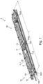
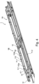
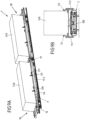
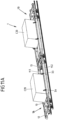
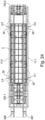
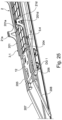
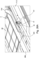
- the attached Figures 1 to 27 show in different views and configurations a freight wagon designed as a double pocket wagon 1, which is characterized by a special flexibility with regard to the transportability of a wide variety of loads.
- a freight wagon designed as a double pocket wagon 1 which is characterized by a special flexibility with regard to the transportability of a wide variety of loads.
- the double pocket wagon 1 of the Figures 1 to 27 Both goods that can be craned and non-craneable cargo, in particular semi-trailers, tractor units and ISO containers of different sizes, can be transported.
- the double pocket wagon 1 has two pocket wagons 1A and 1B which are coupled to one another in an articulated manner.
- the pocket wagons are basically designed identically, so that the features explained below for one of the pocket wagons 1A or 1B also apply to the other pocket wagon 1B or 1A.
- the double pocket wagon 1 has a total length I of approximately 34 m and meets the requirements of the clearance profile G1 for international freight transport.
- the double pocket wagon 1 comprises three bogies DG1, DG2 and DG3 for rail-bound transport.
- a bogie DG1 or DG3 is provided on a head piece 12 of a pocket wagon 1A or 1B, while the one bogie DG2 is provided in the middle in the area of an articulated connection G of the two pocket wagons 1A and 1B on the double pocket wagon 1.
- the two pocket wagons 1A and 1B are each coupled to one another via an end piece 13.
- a head piece 12 and an end piece 13 of a pocket wagon 1A or 1B each form a wagon-side loading area 120 or 130 on the double pocket wagon 1 shown.
- a pin holder 121 for a king pin of a semi-trailer is provided in the area of a first loading area 120 of the head piece 12.
- two longitudinal beams 11.1 and 11.2 extend opposite one another, via which a head piece 12 and end piece 13 are connected to one another.
- a pocket 10 with a length of at least 9 m, in particular of at least 10 m, is defined.
- This pocket 10 is only bordered all around by the two longitudinal beams 11.1 and 11.2 and the head piece 12 and the end piece 13 of a pocket wagon 1A or 1B. Therefore, no further support structure is provided between the longitudinal beams 11.1 and 11.2 connecting the two longitudinal beams 11.1 and 11.2 or the head piece 12 and the end piece 13.
- the pocket 10 is thus only designed as a continuous recess without additional transverse or longitudinal stiffening support structures and is enclosed on the circumference by a frame-like structure made up of the head piece 12, the two longitudinal beams 11.1 and 11.2 and the end piece 13.
- a removable (insert) tray 2 is placed in each pocket 10 of a pocket wagon 1A or 1B of the double pocket wagon 1 shown.
- a tray 2 is suspended from fastening elements designed as suspension pins 110a and 110b on the two opposite longitudinal beams 11.1 and 11.2.
- a tub 2 has a flat tub loading surface 20 on which, for example, a semi-trailer or a tractor unit can be positioned.
- the tub 2 forms connecting elements in the form of four hanging tabs 21a to 21d. Two on each long side of the tub 2
- the suspension tabs 21a/21b or 21c/21d are designed and intended for attachment to one of the longitudinal beams 11.1, 11.2.
- each individual suspension tab 21a to 21d forms a connecting opening 210, into which a suspension pin 110a or 110b formed on the longitudinal beam 11.1 or 11.2 can engage in a form-fitting manner when the tub 2 is suspended, for example by means of a reach stacker or a gantry crane.
- each suspension pin 110a or 110b forms a cylindrical body 1100 that projects inwards on the respective longitudinal beam 11.1, 11.2 and has a head 1101 at the end.
- a suspension tab 21a to 21d of the tub 2 is suspended via its connecting opening 210 onto the body 1100 of the suspension pin 110a or 110b, so that an upper edge of the respective suspension tab 21a to 21d is present between an inner side of the respective longitudinal beam 11.1 and 11.2 and the head 1101 of the associated suspension pin 110a or 110b when the tub 2 is inserted into a pocket 10 as intended.
- transport webs 211 with through openings are formed at an upper end of each suspension tab 21a to 21d.
- a conventional loading system e.g. a reach stacker or gantry crane, can engage in the through openings of the transport paths 211 in order to remove a tub 2 from the respective pocket 10 or to hang it in the pocket 2.
- the trough loading area 20 of the trough 2 is lower than the loading areas 120 and 130 of the head section 12 and the end section 13. This circumstance is used in the present case to enable the transport of container-shaped cargo without having to use the trough 2.
- Container-shaped cargo can thus be transported with the double pocket wagon 1 of the Figures 1 to 27 be transported independently of the tub 2.
- the tub 2 can therefore remain suspended from the longitudinal members 11.1 and 11.2 in the respective pocket 10, even if no cargo is being transported with the tub 2.
- each pocket wagon 1A, 1B of the double pocket wagon 1 has additional fastening elements in the form of attachment pins 300 and 40 in the area of a pocket 10, to which ISO containers of different types and sizes can be fixed as intended. can be carried out without the tub 2 having to be removed or positioned in the pocket 10.
- several different attachment pins 300 and 40 are provided on each pocket wagon 1A or 1B in the area of the longitudinal beams 11.1 and 11.2 in order to be able to transport container-shaped loads of different sizes on and in the pocket 10.
- each longitudinal beam 11.1 and 11.2 several, in this case at least two pairs of different attachment pins 300, 40 are provided on each longitudinal beam 11.1 and 11.2.
- at least two (upper) attachment pin units 3.1, 3.2 or 3.3, 3.4 are provided on an upper edge of each longitudinal beam 11.1 and 11.2.
- Each of these attachment pin units 3.1 to 3.4 engages with a bearing block 31 around an upper edge of the respective longitudinal beam 11.1 or 11.2.
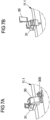
- a pivot bearing part 30 is pivotally mounted on this bearing block 31.
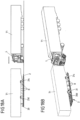
- the attachment pin 300 is in turn formed on the pivot bearing part 30, which can thus be moved via the pivot bearing part 30 between a non-use position according to the Figures 6B and 7B and a usage position according to the Figures 5A , 6A and 7A can be pivoted on the longitudinal beam 11.1 or 11.2.
- a use position the pivot bearing part 30 with the attachment pin 300 extends into the pocket 10 so that a container can be secured to it.
- the attachment pin 300 is pivoted outwards from the pocket 10.
- a container can thus be arranged on the double pocket wagon 1 without being secured to the attachment pin units 3.1 to 3.4 (see e.g. Figures 8A to 9B ) and, if necessary, also past the attachment pin units 3.1 to 3.4 into the interior of the pocket 10 (see e.g. F Figures 11A to 11B ).
- the attachment pin units 3.1 to 3.4 can generally be fixedly positioned on the longitudinal beams 11.1 and 11.2.
- the attachment pin units 3.1 to 3.4 can be freely positioned, in particular rolled, along a longitudinal beam 11.1, 11.2 in the area of the pocket 2.
- differently distributed fastening points for different variants of ISO containers and swap bodies to be attached to the longitudinal beams 11.1, 11.2 can be provided via the attachment pin units 3.1 to 3.4.
- the (upper) attachment pin units 3.1 to 3.4 can also be releasably fixed to the longitudinal beams 11.1 and 11.2, so that an attachment pin unit 3.1 to 3.4 can also be completely removed from a longitudinal beam 11.1 or 11.2 if necessary.
- attachment pin units are provided on the inside of the longitudinal beams 11.1 and 11.2.
- Two attachment pin units are provided on each longitudinal beam 11.1, 11.2, of which only attachment pin units 4.1, 4.2 and 4.4 are visible in the attached figures.
- Each attachment pin unit 4.1, 4.2 or 4.4 has a bearing block 41, via which the respective attachment pin unit 4.1, 4.2 or 4.3 is held on the inside of a longitudinal beam 11.1 or 11.2.
- An attachment pin 40 is formed on each bearing block 41, which can be used to fix an ISO container.
- the individual attachment pin units 4.1, 4.2 and 4.4 can in principle also be mounted longitudinally displaceably on a longitudinal beam 11.1 or 11.2 in order to achieve additional flexibility for different container sizes and to be able to position the attachment pin units in different positions on a longitudinal beam 11.1 or 11.2.
- the position and number of the attachment pin units 3.1 to 3.4 and 4.1, 4.2, 4.4 are not limited.
- An additional attachment pin unit 3.5 can be provided on a longitudinal beam 11.2.
- the attachment pin units 3.1 to 3.5 as well as 4.1, 4.2 and 4.4 can be designed to be rollable in order to be able to accommodate ISO containers and swap bodies of different sizes both above and within a pocket 10 on the double pocket wagon 1.
- the configuration of the double pocket wagon 1 shown enables, in particular, flexible loading of the double pocket wagon 1 with containers C45, C40 and C20 of different sizes.
- a 45-foot container C45 can be loaded onto each pocket wagon 1A, 1B.
- Such a 45-foot container C45 is placed on the loading surfaces 120 and 130 of the head piece 12 and the end piece 13.
- the pivotally mounted attachment pins 300 of the attachment pin units 3.1 to 3.4 are pivoted into a non-use position.
- the respective 45-foot container C45 is neither located on a trough 2 nor within a pocket 10 of the pocket wagon 1A or 1B.
- the double pocket wagon 1 is rather structured in such a way that the 45-foot container C45 extends over the pocket 10 and the trough loading surface 20 of the suspended trough 2 when loaded as intended. Even when loaded with a 45-foot container C45, the tub 2 can be easily transported by hanging it on the longitudinal beams 11.1 and 11.2.
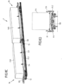
- Figures 8A to 8D the double pocket wagon 1 loaded with two 45-foot containers C45 without tubs 2, while the Figures 9A and 9B illustrate the same loading situation with two 45-foot containers C45 with suspended trays 2.
- a 40-foot container C40 is given a transport position via the attachment pins 300 of the upper attachment pin units 3.1 to 3.4 pivoted into their position of use, in which position these 40-foot containers C40 also extend over a pocket 10 and thus over a tub 2 suspended therein.
- the 20-foot containers C20 do rest partially within a pocket 10 via the attachment pin units 4.1, 4.2 and 4.4 arranged on the inside of the longitudinal beams 11.1 and 11.2 (and thus within the pocket 10) when they have been loaded onto the double pocket wagon 1 as intended.
- the arrangement of the attachment pin units 4.1, 4.2 and 4.4 in relation to the suspension pins 110a and 110b for the suspended tub 2 ensures that the 20-foot container C20 is located in the transport position specified for it above the tub loading surface 20 of the suspended tub 2 and therefore neither rests on the tub loading surface 20, nor is the transportability of the tub 2 affected by loading with a 20-foot container C20.
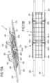
- the trough 2 has a Figures 12A to 16B Ramp assembly 200 shown in different configurations and ramp positions.
- This ramp assembly 200 comprises several (in this case four) ramps 201, 202, 203 and 204 as well as two ramp extensions 205 and 206.
- the ramps 201 to 204 and ramp extensions 205, 206 of the ramp assembly 200 are connected to the Tub loading area 20 different ramp positions are specified, which simplify efficient loading of tub 2 with different loads.
- each ramp 201 to 204 is arranged in pairs with ramp extensions 205, 206 accommodated between two ramps 201/204 or 202/203.
- Each ramp 201 to 204 has a joint bearing part 201a, 202b, 203c or 204d, via which the respective ramp 201, 202, 203 or 204 is fixed to the tub loading surface 20.
- a ramp unit 200a, 200b, 200c or 200d of a ramp 201, 202, 203 or 204 is articulated to each joint bearing part 201a to 204d.
- the respective ramp unit 200a, 200b, 200c or 200d of a ramp 201, 202, 203 or 204 is in the Figures 12A to 12B illustrated (first) ramp position does not extend beyond the longitudinally extended tub loading surface 20 or at most extends slightly beyond it and is positioned essentially centrally on the tub loading surface 20.
- the two ramp extensions 205 and 206 are also releasably fixed to the joint bearing parts 201a to 204a via fixing pins 200.1 and 200.2 and are thus also held in its defined position on the ramp surface 20 of the tub 2.
- the Figures 12A and 12B The first ramp position of the ramp assembly 200 shown is for loading the trough 2 with a semi-trailer T1 or T2 according to the Figures 17A and 18B set up and provided.
- the semi-trailer T1 can be driven into the trough 2 by means of a tractor unit L and secured to the trough loading area 2 (cf. Figures 18A and 18B ).
- the individual components of the ramp assembly 200 are then located centrally between the wheels R of the semi-trailer T1.
- the semi-trailer T1 which has been driven into the trough 2 and secured thereto, can then be loaded into the pocket 10 of a pocket wagon 1A or 1B of the double pocket wagon 1 by means of the trough 2, as shown in the Figures 17A and 17B for the two semi-trailers T1 and T2.
- a kingpin of the respective semi-trailer T1 or T2 is then received and secured on the pin holder 121 of the respective head piece 12.
- a ramp assembly 200 can also be arranged on the tub 2 in a predetermined second ramp position.
- the ramps 201 to 204 are offset transversely and parallel in comparison to the first ramp position with respect to an extension direction of the ramps 201 to 204.
- the ramps 201 to 204 offset parallel protrude further beyond a front edge of the tub 2 than in the first ramp position and thus provide a transport surface extended beyond the edge of the tub 2 for a tractor unit L1 to L4 (cf. e.g. Figure 19 ).
- the individual ramps 201 to 204 are arranged in pairs in the area of the two longitudinal ends of the tub loading area 20, so that each ramp 201 to 204 with its ramp unit 200a to 200d protrudes beyond a front end of the tub loading area 200.
- the ramp extensions 205 and 206 can then also be arranged on two ramps 201 and 204 assigned to a longitudinal side, so that drivable ramps of different lengths protrude from the two front sides of the tub loading area 20.
- the ramps 201 to 204 of the two pairs of ramps 201/204 and 202/203 are arranged transversely spaced from one another essentially in accordance with the track width of a tractor unit L1 to L4, so that a tractor unit L1, L2, L3 or L4 driven into the tub 2 can be driven on in accordance with the Figures 19 , 20 and 21A to 21B with its wheels on ramps 201 to 204 and ramp extensions 205 and 206.
- the pivotable mounting on the articulated bearing parts 201a to 204d ensures that when the trough 2 is hung with the tractor units L1/L2 or L3/L4 positioned on it, two tractor units L1 and L2 or L3 and L4 positioned on a trough 2 are tilted towards each other in the pocket 10 in which the trough 2 is hung, and can thus be arranged in a more space-saving manner.
- the ramps 201 to 204 cannot be accommodated within the trough 2 and rest against the head piece 12 and the end piece 13 during the loading process.
- the protruding ramp units 200a to 200d are pivoted on the articulated bearing parts 201a to 204d.
- the second ramp position of the ramp assembly 200 is accordingly predetermined in such a way that tractor units L1, L2 or L3, L4 positioned on the tub 2 are tilted towards one another when the tub 2 is hung in the pocket 1 and otherwise without any further action.
- the ramp extensions 205 and 206 do not necessarily have to be arranged on the ramps 201 to 204.
- the ramp extensions 205 and 206 can also remain fixed in the middle between two ramps 201, 204 or 202, 203 on the trough loading area 20. In this way, the ramp extensions 205 and 206 can be carried without any problems, even if no tractor units L1 to L4 are positioned on them, for example because only two-axle tractor units L2, L3 are to be carried on the double pocket wagon 1.
- the proposed construction of the double pocket wagon 1 with the trough 2 suspended in the pocket 10 also easily allows the transport of a single tractor unit L2.
- the tractor unit 2 is then completely positioned on the trough loading area 20 and transported by means of the trough 2 in the pocket 10 of a pocket wagon 1A or 1B double pocket wagon 1.
- the double pocket wagon 1 can also be used for loading with cargo using the roll-on/roll-off method.
- a functional position on the pocket 10 is specified via the attachment pins 300 of the upper attachment pin units 3.1 to 3.4 of each tub 2 of a pocket wagon 1A, 1B, which are pivoted into a position of use, in which the tub loading surface 20 of the respective tub 2 is positioned at the level of the loading surfaces 120 and 130 of the head piece 12 and the end piece 13.
- a head piece-side loading surface 120, the tub loading surface 20 of the tub 2 and an end piece-side loading surface 130 thus provide a continuous wagon loading surface in the manner of a flat wagon, onto which cargo can be driven.
- the attachment units 3.1 to 3.4 can also be positioned differently, in particular differently compared to a position on the longitudinal beams 11.1 and 11.2, which the attachment pin unit 3.1 to 3.4 assume for loading the double pocket wagon 1 with one or more 40-foot containers.
- the tray 2 has connection openings on its underside in order to be able to place the tray 2 on the attachment pins 300 of the attachment pin units 3.1 to 3.4 and to fix it thereto. In this case, additional fastening or Fixing elements not necessary.
- the double pocket wagon 1 can be configured almost arbitrarily for the transport of different loads using the trough 2 and the fastening elements provided on the opposite longitudinal beams 11.1, 11.2 in the form of the attachment pin units 3.1 to 3.4 and 4.1, 4.2, 4.4.
- the ramp assembly 200 of the trough 2 can also be in the second ramp position so that tractor units L5 to L8 can be driven onto the ramps 201 to 204 and, if necessary, the ramp extensions 205 and 206.
- conventional loading ramps 207 and 208 are fixed to a head piece 12.
Landscapes
- Engineering & Computer Science (AREA)
- Transportation (AREA)
- Mechanical Engineering (AREA)
- Loading Or Unloading Of Vehicles (AREA)
- Handcart (AREA)
- Connection Of Plates (AREA)
- Fittings On The Vehicle Exterior For Carrying Loads, And Devices For Holding Or Mounting Articles (AREA)
Applications Claiming Priority (3)
| Application Number | Priority Date | Filing Date | Title |
|---|---|---|---|
| DE102018204089.3A DE102018204089A1 (de) | 2018-03-16 | 2018-03-16 | Güterwagen zum Transport von Ladegut und Wanne für einen solchen Güterwagen |
| EP19715004.8A EP3765344B1 (fr) | 2018-03-16 | 2019-03-15 | Wagon pour le transport de chargements |
| PCT/EP2019/056614 WO2019175420A1 (fr) | 2018-03-16 | 2019-03-15 | Wagon marchandises pour le transport de chargements et logement pour un tel wagon marchandises |
Related Parent Applications (1)
| Application Number | Title | Priority Date | Filing Date |
|---|---|---|---|
| EP19715004.8A Division EP3765344B1 (fr) | 2018-03-16 | 2019-03-15 | Wagon pour le transport de chargements |
Publications (2)
| Publication Number | Publication Date |
|---|---|
| EP4410631A2 true EP4410631A2 (fr) | 2024-08-07 |
| EP4410631A3 EP4410631A3 (fr) | 2024-10-30 |
Family
ID=66001167
Family Applications (2)
| Application Number | Title | Priority Date | Filing Date |
|---|---|---|---|
| EP19715004.8A Active EP3765344B1 (fr) | 2018-03-16 | 2019-03-15 | Wagon pour le transport de chargements |
| EP24183987.7A Pending EP4410631A3 (fr) | 2018-03-16 | 2019-03-15 | Wagon de marchandises pour le transport de marchandises |
Family Applications Before (1)
| Application Number | Title | Priority Date | Filing Date |
|---|---|---|---|
| EP19715004.8A Active EP3765344B1 (fr) | 2018-03-16 | 2019-03-15 | Wagon pour le transport de chargements |
Country Status (4)
| Country | Link |
|---|---|
| US (1) | US12576892B2 (fr) |
| EP (2) | EP3765344B1 (fr) |
| DE (3) | DE102018204089A1 (fr) |
| WO (1) | WO2019175420A1 (fr) |
Families Citing this family (5)
| Publication number | Priority date | Publication date | Assignee | Title |
|---|---|---|---|---|
| RU194701U1 (ru) * | 2019-09-25 | 2019-12-19 | Владимир Владимирович Иванов | Вагон-платформа для перевозки автомобильных полуприцепов |
| RU197466U1 (ru) * | 2019-10-22 | 2020-04-29 | Иванов Владимир Владимирович | Сочленённый вагон-платформа для перевозки автомобильных тягачей, автомобильных полуприцепов и крупнотоннажных контейнеров |
| RU2749930C1 (ru) * | 2020-01-20 | 2021-06-21 | Владимир Владимирович Иванов | Способ погрузки автомобильного полуприцепа на вагон-платформу |
| RU203169U1 (ru) * | 2020-08-21 | 2021-03-24 | Квитко Виктор Владимирович | Устройство для перевозки крупнотоннажных контейнеров в полувагонах и ином открытом подвижном составе |
| PL246594B1 (pl) * | 2022-11-20 | 2025-02-17 | Astra Rail Project S R O | Wagon kieszeniowy |
Citations (3)
| Publication number | Priority date | Publication date | Assignee | Title |
|---|---|---|---|---|
| DE4112995A1 (de) | 1991-04-20 | 1992-11-05 | Karl F Riese | Eisenbahn-spezialwagen mit kraftschluessig eingehaengter wanne fuer den transport von lastkraftwagen |
| EP0619211B1 (fr) | 1993-04-08 | 1997-07-16 | Parkany Gmk | Wagon de chemin de fer pour le transport de semi-remorques |
| EP1712444B1 (fr) | 2005-04-14 | 2007-11-07 | Arbel Fauvet Rail S.A. | Nacelle amovible destinée à recevoir une semi-remorque, wagon équipé d'une telle nacelle et procédé de chargement de la semi-remorque |
Family Cites Families (38)
| Publication number | Priority date | Publication date | Assignee | Title |
|---|---|---|---|---|
| FR1476665A (fr) | 1966-02-02 | 1967-04-14 | Cimt Comp Ind Mat Transport | Perfectionnements aux wagons de transport ferroviaire de véhicules routiers notamment de semi-remorques |
| EP0064053A1 (fr) | 1980-02-01 | 1982-11-10 | BEHRENS, Claus-Peter | Wagon a plateforme surbaissee pour le ferroutage de vehicules automobiles et de conteneurs geants |
| US4743150A (en) | 1986-07-28 | 1988-05-10 | Holland Company | Elevatable hitch assembly with lateral slot for trailer on flatcar |
| DE9102001U1 (de) | 1991-02-20 | 1991-06-06 | Bachnick, Martina, 1000 Berlin | KFZ-Auffahrbühne |
| DE9105054U1 (de) * | 1991-04-25 | 1991-06-13 | Waggonfabrik Talbot, 5100 Aachen | Eisenbahngüterwagen |
| DE9207500U1 (de) * | 1992-06-03 | 1992-07-30 | Waggonfabrik Talbot, 5100 Aachen | Eisenbahngüterwagen |
| EP0576852A1 (fr) * | 1992-06-27 | 1994-01-05 | Waggonfabrik Talbot GmbH & Co.KG | Wagon ferroviaire à deux essieux |
| US5890855A (en) | 1994-04-15 | 1999-04-06 | Claps; William R. | Method and apparatus for transporting cars |
| DE4429710A1 (de) | 1994-08-22 | 1996-02-29 | Jun Alexander Faller | Verfahren und Vorrichtung zum Umschlagen von Ladung |
| DE19546300C1 (de) | 1995-10-04 | 1997-04-30 | Matthias Gradenwitz | Cargosystem mit Rotationsbrücken zum Be- und Entladen von Kraftfahrzeugen auf Eisenbahnzügen |
| US5845356A (en) | 1996-07-19 | 1998-12-08 | Braj Enterprise Inc. | Loading ramp and handling apparatus |
| DE19782025T1 (de) | 1996-09-07 | 2000-08-03 | Clive Smith Martin | Multi-Deck Container |
| ATE279345T1 (de) | 1998-12-15 | 2004-10-15 | Walter Back Fa | Verladesystem für fahrzeuge auf und von eisenbahnwaggons |
| DE20023310U1 (de) | 1999-06-25 | 2004-02-26 | Weidemann, Hans-Jürgen, Dr. | Einrichtung zur Be- und Entladung von Schienenwaggons für den kombinierten Schienenverkehr |
| FI20000618A0 (fi) | 2000-03-16 | 2000-03-16 | Peramar Oy | Menetelmä ja laitteisto autojen kuljettamiseksi |
| FR2810609B1 (fr) | 2000-06-21 | 2002-12-27 | Lohr Ind | Wagon pour le transport combine rail/route comprenant deux plates-formes d'extremite supportant une structure ferroviaire pivotante porteuse de la charge routiere |
| FR2819471B1 (fr) | 2001-01-12 | 2003-02-28 | Lohr Ind | Unite ferroviaire a structure porteuse pivotante pour le transport combine rail/route soit d'une semi-remorque soit de deux vehicules a moteur |
| US6533510B2 (en) | 2001-07-23 | 2003-03-18 | International Transport Logistics, Inc. | Carrier for a trailer, system thereof using a stacking device, and method thereof |
| FR2836882B1 (fr) | 2002-03-11 | 2004-06-25 | Jean Pierre Henri Desmoulins | Systeme pour le transport de vehicules routiers sur trains constitue de materiel roulant et dispositifs de manutention specialises |
| DE10230110A1 (de) * | 2002-07-04 | 2004-01-15 | Weidemann, Hans-Jürgen, Dr. | Verfahren zum Be- und Entladen von Schienenwaggons sowie Vorrichtung, Waggongestell und Waggonaufsatz zum Durchführen des Verfahrens |
| US7950891B2 (en) | 2002-07-04 | 2011-05-31 | Hans-Juergen Weidemann | Method for the loading and unloading railway wagons and device, wagon chassis and wagon attachment for carrying out said method |
| FR2850929B3 (fr) | 2003-02-06 | 2005-01-07 | Jean Claude Ramel | Dispositif pour le transport ferroviaire de vehicules de type poids lourds |
| EP1582496B1 (fr) | 2004-03-31 | 2010-04-14 | ISU-System GmbH | Procédé pour manipuler une semi-remorque et moyens de saisie pour la mise en oeuvre de ce procédé |
| DE102006012208B4 (de) * | 2006-03-16 | 2015-02-19 | Cargobeamer Ag | Waggon |
| DE102009015775B4 (de) | 2009-03-31 | 2021-11-25 | Cargobeamer Ag | Arretiervorrichtung zum Arretieren eines Königszapfens eines Sattelaufliegers, sowie Schienenwaggon mit einer derartigen Vorrichtung |
| RU2500560C2 (ru) * | 2009-04-16 | 2013-12-10 | К Текнолоджи АБ | Железнодорожный вагон и способ его загрузки |
| WO2011146190A2 (fr) | 2010-05-18 | 2011-11-24 | Sonoco Development, Inc. | Rampe conçue sur le papier |
| FR2965257A1 (fr) | 2010-09-27 | 2012-03-30 | Combiwest | Systeme de manutention par soulevement d'une remorque |
| PT105760A (pt) * | 2011-06-15 | 2013-02-08 | Luis Filipe Da Guia Nunes | Vagão ferroviário multimodal, método de funcionamento de entrada e saída de mercadorias e respectiva utilização |
| DE102015201387B4 (de) | 2014-01-30 | 2019-06-13 | Bayernhafen GmbH & Co. KG | Verladevorrichtung |
| EP3268257B1 (fr) * | 2015-03-11 | 2019-12-25 | Kässbohrer Transport Technik GmbH | Dispositif de transport levable |
| DE102016011384A1 (de) * | 2016-09-21 | 2018-03-22 | Paul Bunzel | Güterwagen zur gleisgebundenen Beförderung von autarken Transportfahrzeugen |
| CN206406917U (zh) * | 2016-12-28 | 2017-08-15 | 中车山东机车车辆有限公司 | 一种铁路驮背‑集装箱运输平车 |
| ES2611926B1 (es) | 2017-02-13 | 2018-02-27 | Construcciones Y Auxiliar De Ferrocarriles, S.A. | Vagón ferroviario para transporte de semiremolques y contenedores |
| CN107472265B (zh) | 2017-09-20 | 2023-06-02 | 中车山东机车车辆有限公司 | 一种移动式集装箱锁及铁路驮背集装箱运输车辆 |
| EP3604075B1 (fr) * | 2018-08-03 | 2021-02-24 | Kässbohrer Transport Technik GmbH | Dispositif porteur élevable |
| PL3604072T3 (pl) * | 2018-08-03 | 2022-05-23 | Kässbohrer Transport Technik Gmbh | Podnoszone urządzenie nośne |
| CN109177990A (zh) * | 2018-10-09 | 2019-01-11 | 陈红颖 | 一种可装载多个双层集装箱或公路半挂车的车体 |
-
2018
- 2018-03-16 DE DE102018204089.3A patent/DE102018204089A1/de active Pending
-
2019
- 2019-03-15 EP EP19715004.8A patent/EP3765344B1/fr active Active
- 2019-03-15 EP EP24183987.7A patent/EP4410631A3/fr active Pending
- 2019-03-15 DE DE202019005981.4U patent/DE202019005981U1/de active Active
- 2019-03-15 DE DE202019005980.6U patent/DE202019005980U1/de active Active
- 2019-03-15 US US17/438,544 patent/US12576892B2/en active Active
- 2019-03-15 WO PCT/EP2019/056614 patent/WO2019175420A1/fr not_active Ceased
Patent Citations (3)
| Publication number | Priority date | Publication date | Assignee | Title |
|---|---|---|---|---|
| DE4112995A1 (de) | 1991-04-20 | 1992-11-05 | Karl F Riese | Eisenbahn-spezialwagen mit kraftschluessig eingehaengter wanne fuer den transport von lastkraftwagen |
| EP0619211B1 (fr) | 1993-04-08 | 1997-07-16 | Parkany Gmk | Wagon de chemin de fer pour le transport de semi-remorques |
| EP1712444B1 (fr) | 2005-04-14 | 2007-11-07 | Arbel Fauvet Rail S.A. | Nacelle amovible destinée à recevoir une semi-remorque, wagon équipé d'une telle nacelle et procédé de chargement de la semi-remorque |
Also Published As
| Publication number | Publication date |
|---|---|
| EP3765344C0 (fr) | 2024-06-26 |
| DE202019005981U1 (de) | 2023-10-25 |
| EP4410631A3 (fr) | 2024-10-30 |
| WO2019175420A1 (fr) | 2019-09-19 |
| DE202019005980U1 (de) | 2023-10-25 |
| EP3765344B1 (fr) | 2024-06-26 |
| EP3765344A1 (fr) | 2021-01-20 |
| DE102018204089A1 (de) | 2019-09-19 |
| US20220144317A1 (en) | 2022-05-12 |
| US12576892B2 (en) | 2026-03-17 |
Similar Documents
| Publication | Publication Date | Title |
|---|---|---|
| EP3765344B1 (fr) | Wagon pour le transport de chargements | |
| EP3604075B1 (fr) | Dispositif porteur élevable | |
| DE3787973T2 (de) | Vorrichtung und verfahren zum verbessern von intermodalbehältern für den transport von fahrzeugen. | |
| EP3268257B1 (fr) | Dispositif de transport levable | |
| DE1630282A1 (de) | Wahlweise als Einzelanhaenger an eine Strassenzugmaschine oder Tandemanhaenger hinter einen identischen Anhaenger ankuppelbare Fahrgestelleinheit | |
| EP3699058B1 (fr) | Agencement d'un véhicule ferroviaire et dispositif support | |
| DE69213089T2 (de) | Mobiles Ladeflächensystem | |
| DE202015106050U1 (de) | Entfernbare Rahmensysteme für den Fahrzeugtransport | |
| EP3699057B1 (fr) | Dispositif porteur élevable | |
| WO2020177809A1 (fr) | Châssis d'un véhicule ferroviaire | |
| DE3240329A1 (de) | Verfahren und vorrichtung zum transport von containern auf eisenbahnwaggons | |
| CH691314A5 (de) | Gleisbaumaschine. | |
| EP4032777B1 (fr) | Dispositif porteur et wagon poche | |
| DE102007004619A1 (de) | Modul-Wechselrahmen | |
| DE29801555U1 (de) | Aufbau für ein Transportfahrzeug | |
| DE69518429T2 (de) | Verfahren und vorrichtung zum be-und entladen eines güterfahrzuges | |
| DE2713883A1 (de) | Transportfahrzeug | |
| DE9105882U1 (de) | Güterwaggon der Eisenbahn | |
| DE9110124U1 (de) | Sattelanhänger | |
| EP3604072A1 (fr) | Dispositif porteur élevable | |
| DE29606845U1 (de) | Hilfsrahmen für einen Lastkraftwagen für den Transport von Wechselbehältern | |
| DE69803486T2 (de) | Auf gleisen vefahrbares frachtfahrzeug | |
| EP3296175B1 (fr) | Procede de transport de semi-remorque | |
| DE102019126508B4 (de) | Nutzfahrzeug | |
| DE102014114996B4 (de) | System zur variablen Beladung eines Fahrzeugs |
Legal Events
| Date | Code | Title | Description |
|---|---|---|---|
| PUAI | Public reference made under article 153(3) epc to a published international application that has entered the european phase |
Free format text: ORIGINAL CODE: 0009012 |
|
| STAA | Information on the status of an ep patent application or granted ep patent |
Free format text: STATUS: THE APPLICATION HAS BEEN PUBLISHED |
|
| AC | Divisional application: reference to earlier application |
Ref document number: 3765344 Country of ref document: EP Kind code of ref document: P |
|
| AK | Designated contracting states |
Kind code of ref document: A2 Designated state(s): AL AT BE BG CH CY CZ DE DK EE ES FI FR GB GR HR HU IE IS IT LI LT LU LV MC MK MT NL NO PL PT RO RS SE SI SK SM TR |
|
| REG | Reference to a national code |
Ref country code: DE Ref legal event code: R079 Free format text: PREVIOUS MAIN CLASS: B61D0047000000 Ipc: B61D0003180000 Ref country code: DE Ref legal event code: R079 Ref document number: 502019014692 Country of ref document: DE Free format text: PREVIOUS MAIN CLASS: B61D0047000000 Ipc: B61D0003180000 |
|
| PUAL | Search report despatched |
Free format text: ORIGINAL CODE: 0009013 |
|
| AK | Designated contracting states |
Kind code of ref document: A3 Designated state(s): AL AT BE BG CH CY CZ DE DK EE ES FI FR GB GR HR HU IE IS IT LI LT LU LV MC MK MT NL NO PL PT RO RS SE SI SK SM TR |
|
| RIC1 | Information provided on ipc code assigned before grant |
Ipc: B61D 47/00 20060101ALI20240925BHEP Ipc: B61D 3/20 20060101ALI20240925BHEP Ipc: B61D 3/18 20060101AFI20240925BHEP |
|
| STAA | Information on the status of an ep patent application or granted ep patent |
Free format text: STATUS: REQUEST FOR EXAMINATION WAS MADE |
|
| 17P | Request for examination filed |
Effective date: 20250430 |
|
| GRAP | Despatch of communication of intention to grant a patent |
Free format text: ORIGINAL CODE: EPIDOSNIGR1 |
|
| STAA | Information on the status of an ep patent application or granted ep patent |
Free format text: STATUS: GRANT OF PATENT IS INTENDED |
|
| INTG | Intention to grant announced |
Effective date: 20251007 |
|
| GRAS | Grant fee paid |
Free format text: ORIGINAL CODE: EPIDOSNIGR3 |
|
| GRAA | (expected) grant |
Free format text: ORIGINAL CODE: 0009210 |
|
| STAA | Information on the status of an ep patent application or granted ep patent |
Free format text: STATUS: THE PATENT HAS BEEN GRANTED |