EP4414143B1 - Procédé et capteur de distance sans contact pour sécuriser une machine - Google Patents
Procédé et capteur de distance sans contact pour sécuriser une machine Download PDFInfo
- Publication number
- EP4414143B1 EP4414143B1 EP24151463.7A EP24151463A EP4414143B1 EP 4414143 B1 EP4414143 B1 EP 4414143B1 EP 24151463 A EP24151463 A EP 24151463A EP 4414143 B1 EP4414143 B1 EP 4414143B1
- Authority
- EP
- European Patent Office
- Prior art keywords
- virtual
- distance
- distance measurement
- measured value
- distance measuring
- Prior art date
- Legal status (The legal status is an assumption and is not a legal conclusion. Google has not performed a legal analysis and makes no representation as to the accuracy of the status listed.)
- Active
Links
Images
Classifications
-
- B—PERFORMING OPERATIONS; TRANSPORTING
- B25—HAND TOOLS; PORTABLE POWER-DRIVEN TOOLS; MANIPULATORS
- B25J—MANIPULATORS; CHAMBERS PROVIDED WITH MANIPULATION DEVICES
- B25J19/00—Accessories fitted to manipulators, e.g. for monitoring, for viewing; Safety devices combined with or specially adapted for use in connection with manipulators
- B25J19/02—Sensing devices
-
- B—PERFORMING OPERATIONS; TRANSPORTING
- B25—HAND TOOLS; PORTABLE POWER-DRIVEN TOOLS; MANIPULATORS
- B25J—MANIPULATORS; CHAMBERS PROVIDED WITH MANIPULATION DEVICES
- B25J19/00—Accessories fitted to manipulators, e.g. for monitoring, for viewing; Safety devices combined with or specially adapted for use in connection with manipulators
- B25J19/06—Safety devices
- B25J19/066—Redundant equipment
-
- B—PERFORMING OPERATIONS; TRANSPORTING
- B25—HAND TOOLS; PORTABLE POWER-DRIVEN TOOLS; MANIPULATORS
- B25J—MANIPULATORS; CHAMBERS PROVIDED WITH MANIPULATION DEVICES
- B25J9/00—Program-controlled manipulators
- B25J9/16—Program controls
- B25J9/1674—Program controls characterised by safety, monitoring, diagnostic
- B25J9/1676—Avoiding collision or forbidden zones
-
- B—PERFORMING OPERATIONS; TRANSPORTING
- B25—HAND TOOLS; PORTABLE POWER-DRIVEN TOOLS; MANIPULATORS
- B25J—MANIPULATORS; CHAMBERS PROVIDED WITH MANIPULATION DEVICES
- B25J9/00—Program-controlled manipulators
- B25J9/16—Program controls
- B25J9/1694—Program controls characterised by use of sensors other than normal servo-feedback from position, speed or acceleration sensors, perception control, multi-sensor controlled systems, sensor fusion
-
- F—MECHANICAL ENGINEERING; LIGHTING; HEATING; WEAPONS; BLASTING
- F16—ENGINEERING ELEMENTS AND UNITS; GENERAL MEASURES FOR PRODUCING AND MAINTAINING EFFECTIVE FUNCTIONING OF MACHINES OR INSTALLATIONS; THERMAL INSULATION IN GENERAL
- F16P—SAFETY DEVICES IN GENERAL; SAFETY DEVICES FOR PRESSES
- F16P3/00—Safety devices acting in conjunction with the control or operation of a machine; Control arrangements requiring the simultaneous use of two or more parts of the body
- F16P3/12—Safety devices acting in conjunction with the control or operation of a machine; Control arrangements requiring the simultaneous use of two or more parts of the body with means, e.g. feelers, which in case of the presence of a body part of a person in or near the danger zone influence the control or operation of the machine
- F16P3/14—Safety devices acting in conjunction with the control or operation of a machine; Control arrangements requiring the simultaneous use of two or more parts of the body with means, e.g. feelers, which in case of the presence of a body part of a person in or near the danger zone influence the control or operation of the machine the means being photocells or other devices sensitive without mechanical contact
- F16P3/144—Safety devices acting in conjunction with the control or operation of a machine; Control arrangements requiring the simultaneous use of two or more parts of the body with means, e.g. feelers, which in case of the presence of a body part of a person in or near the danger zone influence the control or operation of the machine the means being photocells or other devices sensitive without mechanical contact using light grids
-
- G—PHYSICS
- G01—MEASURING; TESTING
- G01S—RADIO DIRECTION-FINDING; RADIO NAVIGATION; DETERMINING DISTANCE OR VELOCITY BY USE OF RADIO WAVES; LOCATING OR PRESENCE-DETECTING BY USE OF THE REFLECTION OR RERADIATION OF RADIO WAVES; ANALOGOUS ARRANGEMENTS USING OTHER WAVES
- G01S17/00—Systems using the reflection or reradiation of electromagnetic waves other than radio waves, e.g. lidar systems
- G01S17/02—Systems using the reflection of electromagnetic waves other than radio waves
- G01S17/04—Systems determining the presence of a target
-
- G—PHYSICS
- G05—CONTROLLING; REGULATING
- G05B—CONTROL OR REGULATING SYSTEMS IN GENERAL; FUNCTIONAL ELEMENTS OF SUCH SYSTEMS; MONITORING OR TESTING ARRANGEMENTS FOR SUCH SYSTEMS OR ELEMENTS
- G05B19/00—Program-control systems
- G05B19/02—Program-control systems electric
- G05B19/418—Total factory control, i.e. centrally controlling a plurality of machines, e.g. direct or distributed numerical control [DNC], flexible manufacturing systems [FMS], integrated manufacturing systems [IMS] or computer integrated manufacturing [CIM]
- G05B19/4189—Total factory control, i.e. centrally controlling a plurality of machines, e.g. direct or distributed numerical control [DNC], flexible manufacturing systems [FMS], integrated manufacturing systems [IMS] or computer integrated manufacturing [CIM] characterised by the transport system
- G05B19/41895—Total factory control, i.e. centrally controlling a plurality of machines, e.g. direct or distributed numerical control [DNC], flexible manufacturing systems [FMS], integrated manufacturing systems [IMS] or computer integrated manufacturing [CIM] characterised by the transport system using automatic guided vehicles [AGV]
-
- G—PHYSICS
- G05—CONTROLLING; REGULATING
- G05B—CONTROL OR REGULATING SYSTEMS IN GENERAL; FUNCTIONAL ELEMENTS OF SUCH SYSTEMS; MONITORING OR TESTING ARRANGEMENTS FOR SUCH SYSTEMS OR ELEMENTS
- G05B2219/00—Program-control systems
- G05B2219/30—Nc systems
- G05B2219/31—From computer integrated manufacturing till monitoring
- G05B2219/31005—Detect obstacles on path of vehicle
-
- G—PHYSICS
- G05—CONTROLLING; REGULATING
- G05B—CONTROL OR REGULATING SYSTEMS IN GENERAL; FUNCTIONAL ELEMENTS OF SUCH SYSTEMS; MONITORING OR TESTING ARRANGEMENTS FOR SUCH SYSTEMS OR ELEMENTS
- G05B2219/00—Program-control systems
- G05B2219/30—Nc systems
- G05B2219/37—Measurements
- G05B2219/37425—Distance, range
-
- G—PHYSICS
- G05—CONTROLLING; REGULATING
- G05B—CONTROL OR REGULATING SYSTEMS IN GENERAL; FUNCTIONAL ELEMENTS OF SUCH SYSTEMS; MONITORING OR TESTING ARRANGEMENTS FOR SUCH SYSTEMS OR ELEMENTS
- G05B2219/00—Program-control systems
- G05B2219/30—Nc systems
- G05B2219/40—Robotics, robotics mapping to robotics vision
- G05B2219/40317—For collision avoidance and detection
Definitions
- the invention relates to a method and a contactless distance sensor for securing a machine according to the preamble of claims 1 and 14 respectively.
- the primary goal of safety technology is to protect people from sources of danger, such as those posed by machinery in an industrial environment.
- the machine is monitored using sensors, and if a situation arises in which a person is at risk of getting dangerously close to the machine, appropriate safeguarding measures are taken.
- Sensors used in safety technology must be particularly reliable and therefore meet stringent safety requirements, such as the EN13849 standard for machinery safety and the IEC61496 or EN61496 device standard for electro-sensitive protective equipment (ESPE).
- ESE electro-sensitive protective equipment
- the distance sensor is designed to be safe when used in conjunction with the higher-level controller, and to achieve a higher level of safety, tests in the form of a reference run with known reference targets are possible. Approaching surfaces must be specifically taught for each position to ensure that the protective shell is not triggered by the surface.
- Near-surface trajectories such as those required to create an adhesive bead or a weld line, cannot be implemented in this way.
- the conventional approach is also not suitable for dynamic motion behavior, such as the unpredictable trajectory during an evasive movement or a trajectory in response to pose detection of a workpiece to be gripped.
- the EP 3 988 256 A1 Provides a more flexible protective shell by adjusting distance thresholds, which essentially specify the length of the measuring beams. This adjustment takes into account the maximum available distance to the nearest background object. The maximum distance is calculated from the expected path of the line of sight of the securing sensor and the topography of the surroundings. However, problems arise when the assumed line of sight deviates from the actual line of sight, or the assumed topography deviates from the actual surroundings. This is particularly critical for edge hits, where even minor deviations can lead to completely different distances.
- the forward kinematics is usually determined for its workflow anyway. This information can be used to derive the pose of the distance sensor. With the pose of the distance sensor, it is clear, within the accuracy of the pose determination, where its distance measuring beam runs, so that this can be simulated by the first virtual distance measuring beam.
- the invention is based on the basic idea of forming at least one further virtual distance measuring beam and including it in the comparison.
- the at least one another virtual distance measuring beam is offset from the first virtual distance measuring beam. This way, the point of impact on the surface model is determined in a completely analogous manner, and from this, another virtual distance measurement value is calculated.
- the offset corresponds clearly to a possible deviation in the predicted pose of the distance sensor from the actual pose and/or in the surface model from the actual working area.
- the another virtual measured value is therefore another conceivable prediction for the actual measured value.
- a comparison is now made as to whether the actual measured value is compatible with the virtual measured values, i.e. with the first virtual measured value and the another virtual measured value or the other virtual measured values.
- the invention has the advantage of achieving a particularly robust method for object detection.
- additional information about the expected actual measured values is obtained. This allows for a significantly improved judgment as to whether an object is actually located in the distance measuring beam. False detections due to deviating virtual measured values, particularly at edges of the surface model, are eliminated.
- This invention facilitates the possibilities discussed above for securing movements near a work surface or dynamic movements, or even makes them accessible in practice.
- Configuration, import, or measurement of the surface model is preferably carried out in advance.
- the surface model can be at least partially reloaded during a shutdown or even dynamically during runtime. This is useful, for example, when one tray is swapped for another because a change in production is taking place. This production changeover can trigger the reloading of the corresponding surface model automatically or manually.
- the first virtual distance measuring beam is preferably surrounded by a multitude of additional virtual distance measuring beams. This covers a wide range of possible deviations between the first virtual distance measuring beam and the real distance measuring beam of the distance sensor. Object detection becomes particularly robust.
- the starting points of the additional virtual distance measuring beams preferably form a circular line, at least topologically.
- the additional virtual distance measuring beams thus cover deviations in all conceivable directions.
- the additional virtual distance measuring beams effectively form a kind of shell surface emanating from the circular line of their starting points or their respective origin.
- the first virtual distance measuring beam is embedded in this shell.
- a circular line, at least topologically can still be deformed and thus, for example, elliptical or otherwise distorted, including the possibility of corners like a square.
- a circle is particularly preferred in the geometric rather than just topological sense because it is the easiest to handle and best represents the surroundings.
- the surface model is preferably a polygon mesh, particularly a triangular mesh.
- a polygon mesh or mesh allows the contour of the working environment to be quantized in a suitable data structure with any desired precision.
- the polygon mesh is composed of polygon surface elements, which are referred to below as polygons.
- the additional virtual distance measuring beams preferentially hit polygons that are adjacent to one another without gaps.
- the polygons that are hit by the virtual distance measuring beams are connected.
- the density condition can be calibrated at the largest possible distance in the surface model, because for smaller distances, the distances generated by the additional virtual distance measuring beams are hit polygons are even more so seamlessly adjacent.
- the condition of seamlessly adjacent polygons does not have to apply universally, but can, for example, be restricted to surfaces at a limited angle of inclination to the sensor.
- each of the seamlessly adjacent polygons is hit exactly once, at least at the greatest conceivable distance. Multiple hits by several of the additional virtual distance measuring beams are harmless for safety, but cost unnecessary computing time without providing any new information.
- the density condition can be formulated using the angular distance or circumferential distance of the additional virtual distance measuring beams, which must be chosen to be correspondingly small.
- the seamlessly adjacent polygons then form a circular arc within the scope of their discrete resolution, which can be perspectively distorted into an elliptical arc and divided by edges in the working environment.
- virtual measured values for the distance are determined for polygons enclosed by polygons onto which further virtual distance measuring rays impinge. This effectively completes or closes the part of the surface model taken into account by the further virtual distance measuring rays.
- the starting points of the further virtual distance measuring rays form a circle
- the entire circular area is taken into account and no longer just the circle or circumference.
- the impingement of virtual distance measuring rays is primarily an illustration that does not necessarily correspond to the implementation. Enclosed polygons or associated virtual measured values can be determined easily with significantly less effort by calculating a distance between two points in space.
- the actual measured value and the virtual measured values are preferably re-determined and compared cyclically.
- the virtual measured values are thus updated during measurement cycles, preferably for the highest time resolution, with each measurement cycle of the distance sensor. This then results in a detection cycle for object recognition.
- an actual measured value that is greater than all virtual measured values is considered acceptable, and thus, in this case, no object is detected in the distance measuring beam. In this situation, the actual measured value does not match any virtual measured value within the tolerances. However, the object is further away than the working range, and this is harmless from a safety perspective.
- Such handling With an actual measured value that is too large, it is possible to simplify the surface model and, for example, eliminate dents—that is, partial contours of the working environment that are curved outward from the distance sensor's perspective—and replace them with a flat surface.
- the closed-circuit principle always requires a measured value that confirms the model, thus, an actual measured value that is too large is not tolerated.
- the distance sensor preferably has multiple distance measuring beams, with which a respective actual measured value for the distance is determined and compared with virtual measured values from virtual distance measuring beams for a respective distance measuring beam.
- there are multiple real measurements wherein the corresponding distance measuring beams emanate from the same distance sensor, a distance measuring beam each emanates from one of multiple distance sensors, or single- and multi-beam distance sensors are used in a mixture.
- the above method is carried out, i.e., the respective distance measuring beam is simulated by a virtual distance measuring beam, and at least one additional virtual distance measuring beam offset therefrom is formed in order to detect an object in the observed distance measuring beam by comparing the actual measured value of the observed distance measuring beam with the virtual measured values of the associated virtual distance measuring beams.
- the distance measuring beams preferably form a protective dome, whereby no object is detected in the distance measuring beam if the actual measured value exceeds the length of the protective dome.
- the protective dome is located in particular around the tool tip on a robot arm, so that approaches to the tool tip are detected in good time.
- the protective dome does not necessarily have to be closed all the way around, for example if no access from behind is possible for mechanical or other reasons. Objects at a distance greater than the length of the protective dome are not relevant from a safety perspective and are therefore ignored in this embodiment in the object detection.
- the protective dome can be adapted to the surface model, because access is not possible in areas of the protective dome that are thereby shortened, but are blocked by sections of the work area.
- each distance measuring beam in the preferred embodiment with starting points of further virtual Distance measuring beams on a circular line, a separate virtual cylinder or cone shell of the further virtual distance measuring beams is formed.
- the distance measuring beam preferably performs a scanning motion. This is an alternative to using multiple distance measuring beams to achieve a larger area of object detection. The two can be combined, as in the case of a multi-beam laser scanner.
- the virtual distance measuring beams are formed for the respective scanning position of the distance measuring beam.
- the contactless distance sensor according to the invention for securing a machine, in particular a robot arm, and for detecting objects in a working area of the machine has a control and evaluation unit designed to measure an actual measured value for a distance to the working area or an object arranged there and to detect an object in the distance measuring beam based on the actual measured value using a method according to the invention.
- a control and evaluation unit designed to measure an actual measured value for a distance to the working area or an object arranged there and to detect an object in the distance measuring beam based on the actual measured value using a method according to the invention.
- the distance sensor has a light transmitter for emitting a light signal along a distance measuring beam and a light receiver for generating a received signal from the returning light signal, and the control and evaluation unit determines the actual measured value from a light propagation time between the emission and reception of the light signal.
- the control and evaluation unit is preferably not integrated exclusively into the distance sensor itself, but rather at least partially outsourced to a connected system, such as a safety controller or a non-safety controller or other computing unit, which is then secured by redundancy or tests.
- the machine controller can also contain at least parts of the control and evaluation unit. Implementation outside the distance sensor facilitates updating and adaptation to other applications, and it also allows the distance sensor to be kept simpler.
- a control and evaluation unit integrated into the distance sensor or an implementation distributed across the distance sensor and connected computing units is also conceivable.
- the distance sensor is preferably a safe sensor and/or the functionality of the distance sensor is checked cyclically and/or the distance values of several distance sensors are compared with each other to generate safe distance values. Safe distance values are thus obtained.
- the distance sensor itself can be designed in accordance with the standard. Safety can also be achieved through several redundant and/or diversely redundant distance sensors or cyclical function tests, or a higher level of safety can be achieved in this way. Terms such as safe or safety sensor are always to be understood in the context of this description to mean that a safety standard for safety technology applications or for accident prevention in the industrial sector, in particular for machine safety, non-contact protective devices, industrial robots, collaboration with robots or the like, is met. This can be the standards mentioned in the introduction or their successors, extensions or respective equivalents in other regions of the world.
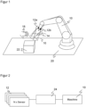
- Figure 1 shows an overview of a robot arm 10 to be protected.
- the robot arm 10 and the specific application are examples, and the following explanations can be applied to any robots and other moving machines and scenarios to be protected, in particular AGVs/AGCs (Automated Guided Vehicle / Container) or drones.
- AGVs/AGCs Automatic Guided Vehicle / Container
- distance sensors 12a-b are mounted on the robot arm 10, preferably in the vicinity of a tool for its safeguarding (EOAS, End-of-Arm Safeguarding).
- the distance sensors 12a-b determine distance values along several distance measuring beams 14.
- the number of two distance sensors 12a-b shown is purely exemplary; there may be more distance sensors or just one distance sensor, which can then preferably measure along several distance measuring beams 14.
- one or more distance measuring beams 14 emanate from each distance sensor 12a-b.
- Distance measuring beams 14 can be approximately geometric beams or have a finite cross-section, for example, if the distance sensor 12a-b operates as an area scanner with a fanned-out light beam.
- the distance measuring beams 14 together form a kind of virtual protective shell or virtual protective bell 16 around the end effector. If, for example, a person reaches into the area protected by the protective bell 16 with their hand 18, the protective bell 16 is considered violated. Therefore, a safety-related reaction of the robot 10 is triggered, which, depending on the violated distance thresholds, can consist of deceleration, evasive action, or an emergency stop.
- a surface model of the work surface 20, including the objects 22 expected thereon is known.
- the surface model corresponds to the 3D contour or topography of the work surface 20 with the objects 22 expected thereon and is preferably already known in advance. For example, it is created manually in a CAD model or an existing surface model, for example of the robot cell, is imported.
- a contour measurement can be carried out, either with the distance sensor 12a-b itself or with a topography sensor attached externally and/or to the robot 10 for teaching the surface model, such as a laser scanner or a 3D camera.
- the surface model can also be newly created or modified during ongoing operation or during an interruption in operation.
- the surface model can be used to predict which distance would have to be measured as long as no object, and in particular no hand 18, is located in the distance measuring beam 14.
- the pose is calculated from the robot movements, whereby this so-called forward kinematics can usually be determined and queried for the robot controller anyway.
- the measuring behavior of the distance sensor 12a-b is thus simulated, and a virtual measured value is generated, which can be compared with the actual measured value of the distance sensor 12a-b in order to discover whether there is anything different in the distance measuring beam 14 than expected according to the surface model. It should be remembered that expected objects 22 are part of the surface model and are therefore ignored by the object detection.
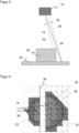
- the distance measuring beam 14 is simulated, but at least one additional virtual measured value is obtained from at least one object adjacent to the simulated distance measuring beam. Additional virtual distance measuring beams are determined and compared. This increases the robustness of the method, particularly in the case of edge hits or in the vicinity of depth jumps in the 3D contour of the working surface 20 with the expected objects 22 located thereon or the corresponding surface model.
- a limited length of the protective dome 16 is sufficient for protection. Accordingly, measured values from the distance sensor 12a-b greater than this length can preferably be ignored in object detection, since it is not safety-relevant whether or not an object is present at such extreme distances.
- an additional virtual distance measuring beam 30 is evaluated for each polygon of the area enclosed by the curve segments 33.
- the first virtual measured value of the first virtual distance measuring beam 28 coincides with one of the inner polygons 36. This redundancy is harmless, but can also be intercepted in the implementation.
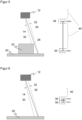
- Figure 5 shows on the left side once again the schematic representation of the Figure 3 and illustrates the virtual measured values in the vicinity of edge 26 on the right.
- the spread between the minimum and maximum virtual measured values is large due to edge 26.
- the intermediate values are not accepted by virtual measured values; the transition at edge 26 is abrupt.
- An actual measured value that is compatible with the surface model, so that no object is detected may only lie within the tolerance ranges 38 around the virtual measured values. If an actual measured value lies within the large remaining sensitive range 40, an object is detected.
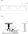
- a simplified surface model 43 is used that ignores these depressions 42 and instead assumes continuous surfaces. This simplification results in the actual measured value in the area of a depression 42 being too large. Accordingly, object detection is only triggered by an actual measured value that is too small, but not by an actual measured value that is too large. In particular, for this special case, the actual measured value must be larger than all virtual measured values. This is permissible from a safety perspective, because it also rules out the possibility of an object having dangerously approached the machine 10.
- Figure 8 shows a schematic representation of a special measurement situation in which an exemplary object 44, which should actually be detected by an object recognition system, is overlooked, although this is not safety-critical.
- This object 44 is arranged on a surface inclined towards the distance sensor 12. Somewhat more generally, there is a depth jump at the object 22 of the surface model or its edge, but the further virtual distance measuring beams 30 also impinge on the connecting surface, which is perpendicular here, so that intermediate values are recorded as virtual measured values.
- the intermediate values with their respective tolerance ranges 38 complement each other to form a continuum in an intermediate range between the minimum and maximum virtual measured value.
- the sensitive range 40 of the object detection is considerably reduced and excludes the intermediate range. An actual measured value for the object 44 is therefore compatible with the virtual measured values, and the object detection does not react to the object 44. This is the case in the situation of Figure 5 quite different, where this intermediate area lies outside the tolerance ranges 38 and is a sensitive area 40.
Landscapes
- Engineering & Computer Science (AREA)
- Mechanical Engineering (AREA)
- Robotics (AREA)
- Physics & Mathematics (AREA)
- General Engineering & Computer Science (AREA)
- General Physics & Mathematics (AREA)
- Electromagnetism (AREA)
- Automation & Control Theory (AREA)
- Quality & Reliability (AREA)
- Manufacturing & Machinery (AREA)
- Computer Networks & Wireless Communication (AREA)
- Radar, Positioning & Navigation (AREA)
- Remote Sensing (AREA)
- Manipulator (AREA)
- Length Measuring Devices By Optical Means (AREA)
- Control Of Position, Course, Altitude, Or Attitude Of Moving Bodies (AREA)
Claims (14)
- Procédé pour sécuriser une machine (10), en particulier un bras de robot, consistant à détecter des objets (18) dans une zone de travail (20, 22) de la machine (10) et à vérifier, pour un objet (18) détecté, si sa présence est autorisée et, dans le cas contraire, à faire passer la machine (10) dans un état de réduction des risques ou de sécurité,les objets (18) étant détectés du fait queau moins un capteur de distance sans contact (12), se déplaçant avec la machine (10), mesure une valeur de mesure réelle pour une distance par rapport à la zone de travail (20, 22) ou à un objet (18) qui y est disposé, au moyen d'au moins un faisceau de mesure de distance (14),un premier faisceau de mesure de distance virtuel (28) est formé à partir d'une pose du capteur de distance (12), lequel simule le faisceau de mesure de distance (14), le lieu d'impact du premier faisceau de mesure de distance virtuel (28) sur un modèle de surface de la zone de travail (20, 22) est déterminé, et une première valeur de mesure virtuelle pour la distance est calculée,et la valeur de mesure réelle est comparée à la première valeur de mesure virtuelle pour décider si un objet (18) se trouve dans le faisceau de mesure de distance (14),sachant queau moins un autre faisceau de mesure de distance virtuel (30) est formé avec un décalage (32) par rapport au premier faisceau de mesure de distance virtuel (28), le lieu d'impact dudit au moins un autre faisceau de mesure de distance virtuel (30) sur le modèle de surface est déterminé, et au moins une autre valeur de mesure virtuelle pour la distance est calculée,caractérisé en ce quela valeur de mesure réelle est comparée aux valeurs de mesure virtuelles, pour savoir si elle est compatible avec celles-ci, en particulier si elle est égale à l'une au moins des valeurs de mesure virtuelles, à une tolérance (38) près,et en ce qu'un objet (18) est détecté dans le faisceau de mesure de distance (14) si la valeur de mesure réelle n'est pas compatible avec les valeurs de mesure virtuelles.
- Procédé selon la revendication 1,
dans lequel le modèle de surface est configuré ou importé, en particulier sous forme de modèle CAO, ou le modèle de surface est mesuré au moyen d'un capteur. - Procédé selon la revendication 1 ou 2,
dans lequel une pluralité d'autres faisceaux de mesure de distance virtuels (30) entourent le premier faisceau de mesure de distance virtuel (28), en particulier, les points de départ des autres faisceaux de mesure de distance virtuels (30) forment, au moins sur le plan topologique, une ligne circulaire. - Procédé selon l'une des revendications précédentes,
dans lequel le modèle de surface est un réseau polygonal, en particulier un réseau triangulaire. - Procédé selon la revendication 4,
dans lequel les autres faisceaux de mesure de distance virtuels (30) rencontrent des polygones (34) voisins sans espace entre eux. - Procédé selon la revendication 4 ou 5,
dans lequel des valeurs de mesure virtuelles de la distance sont déterminées pour des polygones (36) qui sont entourés par des polygones (34) sur lesquels tombent les autres faisceaux de mesure de distance virtuels (30). - Procédé selon l'une des revendications précédentes,
dans lequel les points de départ des autres faisceaux de mesure de distance virtuels (30) forment une grille. - Procédé selon l'une des revendications précédentes,
dans lequel les autres faisceaux de mesure de distance virtuels (30) s'étendent parallèlement ou selon un angle aigu par rapport au premier faisceau de mesure de distance virtuel (28). - Procédé selon l'une des revendications précédentes,
dans lequel la valeur de mesure réelle et les valeurs de mesure virtuelles sont redéterminées et comparées de manière cyclique. - Procédé selon l'une des revendications précédentes,
dans lequel une valeur de mesure réelle supérieure à toutes les valeurs de mesure virtuelles est évaluée comme étant compatible et donc, pour ce cas, aucun objet (18) n'est détecté dans le faisceau de mesure de distance (14). - Procédé selon l'une des revendications précédentes,
dans lequel le capteur de distance (12) présente plusieurs faisceaux de mesure de distance (14) au moyen desquels une valeur de mesure réelle respective pour la distance est déterminée et comparée à des valeurs de mesure virtuelles provenant de faisceaux de mesure de distance virtuels (28, 30) pour un faisceau de mesure de distance respectif (14). - Procédé selon l'une des revendications précédentes,dans lequel les faisceaux de mesure de distance (14) forment une cloche de protection (16), eten particulier, aucun objet (18) n'est détecté dans le faisceau de mesure de distance (14) si la valeur de mesure réelle dépasse une longueur de la cloche de protection (16).
- Procédé selon l'une des revendications précédentes,
dans lequel le faisceau de mesure de distance (14) exécute un mouvement de balayage. - Capteur de distance sans contact (12), en particulier capteur de distance optoélectronique selon le principe du temps de vol de la lumière, pour sécuriser une machine (10), en particulier un bras de robot, et pour détecter des objets (18) dans une zone de travail (20, 22) de la machine (10), le capteur de distance (12) comprenant un émetteur de lumière pour émettre un signal lumineux le long d'un faisceau de mesure de distance (14), un récepteur de lumière pour générer un signal de réception à partir du signal lumineux de retour, et une unité de commande et d'évaluation (24) qui est conçue pour mesurer une valeur de mesure réelle pour une distance par rapport à la zone de travail (20, 22) ou à un objet (18) qui y est disposé, et pour détecter l'objet (18) dans le faisceau de mesure de distance (14) à l'aide de la valeur de mesure réelle par un procédé selon l'une des revendications précédentes.
Applications Claiming Priority (1)
| Application Number | Priority Date | Filing Date | Title |
|---|---|---|---|
| DE102023102951.7A DE102023102951B4 (de) | 2023-02-07 | 2023-02-07 | Verfahren und berührungsloser Distanzsensor zum Absichern einer Maschine |
Publications (3)
| Publication Number | Publication Date |
|---|---|
| EP4414143A1 EP4414143A1 (fr) | 2024-08-14 |
| EP4414143A8 EP4414143A8 (fr) | 2024-12-18 |
| EP4414143B1 true EP4414143B1 (fr) | 2025-04-02 |
Family
ID=91951342
Family Applications (1)
| Application Number | Title | Priority Date | Filing Date |
|---|---|---|---|
| EP24151463.7A Active EP4414143B1 (fr) | 2023-02-07 | 2024-01-11 | Procédé et capteur de distance sans contact pour sécuriser une machine |
Country Status (3)
| Country | Link |
|---|---|
| US (1) | US12570013B2 (fr) |
| EP (1) | EP4414143B1 (fr) |
| DE (1) | DE102023102951B4 (fr) |
Families Citing this family (3)
| Publication number | Priority date | Publication date | Assignee | Title |
|---|---|---|---|---|
| DE102023102951B4 (de) * | 2023-02-07 | 2025-03-13 | Sick Ag | Verfahren und berührungsloser Distanzsensor zum Absichern einer Maschine |
| DE102024112733B3 (de) * | 2024-05-07 | 2025-04-30 | Kuka Deutschland Gmbh | Ermitteln eines Roboterraumbereiches |
| CN120902027B (zh) * | 2025-10-09 | 2025-12-23 | 四川福摩斯工业技术有限公司 | 一种视觉引导机器人上下料的安全防护方法及系统 |
Family Cites Families (20)
| Publication number | Priority date | Publication date | Assignee | Title |
|---|---|---|---|---|
| US6317953B1 (en) * | 1981-05-11 | 2001-11-20 | Lmi-Diffracto | Vision target based assembly |
| DE10324628A1 (de) * | 2003-05-28 | 2004-12-16 | Daimlerchrysler Ag | Steuerverfahren für einen Roboter |
| DE10360174B4 (de) * | 2003-12-20 | 2007-03-08 | Leuze Lumiflex Gmbh + Co. Kg | Vorrichtung zur Überwachung eines Erfassungsbereichs an einem Arbeitsmittel |
| DE102008063081B4 (de) * | 2008-12-24 | 2014-10-23 | Gottfried Wilhelm Leibniz Universität Hannover | Sicherungsvorrichtung und Verfahren zum Betreiben einer mehrgliedrigen Maschine |
| EP2386876B1 (fr) * | 2010-05-04 | 2013-07-10 | Sick AG | Capteur de sécurité optoélectronique mesurant l'éloignement et procédé de surveillance d'une zone de surveillance |
| DE102013020596A1 (de) * | 2013-12-13 | 2015-06-18 | Daimler Ag | Arbeitsstation und Verfahren zum Durchführen wenigstens eines Arbeitsschritts, insbesondere zum Herstellen eines Kraftwagens |
| ITUB20151930A1 (it) | 2015-07-03 | 2017-01-03 | Soilmec Spa | Sistema e metodo di sicurezza per la rilevazione di una condizione di rischio in una regione situata in prossimita' di una macchina operatrice, quale una macchina di perforazione o simile. |
| DE102015112656A1 (de) | 2015-07-31 | 2017-02-02 | Sick Ag | Distanzsensor |
| DE102018118265B4 (de) | 2018-07-27 | 2020-11-12 | Sick Ag | Verfahren und Überwachungssystem zum Absichern einer Maschine |
| DE102018125736B4 (de) * | 2018-10-17 | 2021-02-18 | Sick Ag | Verfahren zum Schutz von Menschen in einer Umgebung einer beweglichen Maschine |
| DE102020101482B3 (de) * | 2020-01-22 | 2021-04-15 | Sick Ag | Sicherheitssystem und Verfahren |
| DE102020127670B4 (de) | 2020-10-21 | 2022-06-30 | Sick Ag | Absichern eines beweglichen Maschinenteils |
| EP4040034B1 (fr) * | 2021-02-04 | 2023-06-07 | Sick Ag | Dispositif de sécurité et procédés de sécurité destiné à la surveillance d'une machine |
| DE102021119372B4 (de) * | 2021-07-27 | 2023-06-07 | Sick Ag | Absichern eines beweglichen Maschinenteils |
| DE102021131060B3 (de) * | 2021-11-26 | 2022-07-28 | Sick Ag | System und Verfahren mit einem System |
| DE102022100840A1 (de) * | 2022-01-14 | 2023-07-20 | Sick Ag | Augmented-reality-system zum unterrichten eines anwenders einer applikation |
| EP4385676B1 (fr) | 2022-12-12 | 2024-11-13 | Sick Ag | Validation de la pose d'un robot et des données d'un capteur se déplaçant avec le robot |
| DE102023102951B4 (de) * | 2023-02-07 | 2025-03-13 | Sick Ag | Verfahren und berührungsloser Distanzsensor zum Absichern einer Maschine |
| DE102023107215A1 (de) * | 2023-03-22 | 2024-09-26 | Sick Ag | System und Verfahren zur Überwachung eines Gefahrenbereichs einer Maschine |
| DE102023107973B4 (de) * | 2023-03-29 | 2025-04-24 | Sick Ag | System und Verfahren zur Überwachung eines Gefahrenbereichs eines Roboters |
-
2023
- 2023-02-07 DE DE102023102951.7A patent/DE102023102951B4/de active Active
-
2024
- 2024-01-11 EP EP24151463.7A patent/EP4414143B1/fr active Active
- 2024-02-06 US US18/434,424 patent/US12570013B2/en active Active
Also Published As
| Publication number | Publication date |
|---|---|
| EP4414143A8 (fr) | 2024-12-18 |
| US12570013B2 (en) | 2026-03-10 |
| EP4414143A1 (fr) | 2024-08-14 |
| US20240261987A1 (en) | 2024-08-08 |
| DE102023102951A1 (de) | 2024-08-08 |
| DE102023102951B4 (de) | 2025-03-13 |
Similar Documents
| Publication | Publication Date | Title |
|---|---|---|
| EP4414143B1 (fr) | Procédé et capteur de distance sans contact pour sécuriser une machine | |
| EP3709106B1 (fr) | Mise en sécurité d'une machine | |
| EP3744482B1 (fr) | Fixation d'une pièce de machine mobile | |
| DE102019110882B4 (de) | Absichern eines beweglichen Maschinenteils | |
| DE102020127670B4 (de) | Absichern eines beweglichen Maschinenteils | |
| EP4124789B1 (fr) | Fixation d'une pièce de machine mobile | |
| DE102010007520B3 (de) | Sicherheitssteuerung mit einer Vielzahl von Anschlüssen für Sensoren | |
| DE102018118265B4 (de) | Verfahren und Überwachungssystem zum Absichern einer Maschine | |
| DE102007007576A1 (de) | Verfahren und Vorrichtung zum Sichern eines Arbeitsraums | |
| EP3650740B1 (fr) | Système de sécurité et procédé de surveillance d'une machine | |
| EP2053538A1 (fr) | Protection d'une zone de surveillance et support visuel d'un usinage automatisé | |
| DE102019212452A1 (de) | Interferenzvermeidungsvorrichtung und Robotersystem | |
| DE102019211770B3 (de) | Verfahren zur rechnergestützten Erfassung und Auswertung eines Arbeitsablaufs, bei dem ein menschlicher Werker und ein robotisches System wechselwirken | |
| EP3470879B1 (fr) | Capteur optoélectronique et procédé de détection sécurisée d'objets | |
| DE102020129823B4 (de) | Visualisieren eines Schutzfeldes | |
| DE202020106491U1 (de) | Visualisieren eines Schutzfeldes | |
| EP4385676B1 (fr) | Validation de la pose d'un robot et des données d'un capteur se déplaçant avec le robot | |
| DE102018109329A1 (de) | Mehrgliedrige aktuierte Kinematik, vorzugsweise Roboter, besonders vorzugsweise Knickarmroboter | |
| EP3825731B1 (fr) | Capteur optoélectronique de sécurité et procédé de détermination sécurisée de position propre | |
| DE202017104603U1 (de) | System zum Absichern einer Maschine | |
| DE202022103234U1 (de) | Überwachungseinrichtung | |
| EP3527332A1 (fr) | Dispositif capteur de sécurité et procédé de sécurisation d'une machine mobile | |
| EP4108390B1 (fr) | Procédé de fonctionnement sécurisé d'une pièce de machine mobile | |
| EP3699634B1 (fr) | Module de capteur | |
| DE202013102415U1 (de) | Optoelektronischer Sensor |
Legal Events
| Date | Code | Title | Description |
|---|---|---|---|
| PUAI | Public reference made under article 153(3) epc to a published international application that has entered the european phase |
Free format text: ORIGINAL CODE: 0009012 |
|
| STAA | Information on the status of an ep patent application or granted ep patent |
Free format text: STATUS: THE APPLICATION HAS BEEN PUBLISHED |
|
| AK | Designated contracting states |
Kind code of ref document: A1 Designated state(s): AL AT BE BG CH CY CZ DE DK EE ES FI FR GB GR HR HU IE IS IT LI LT LU LV MC ME MK MT NL NO PL PT RO RS SE SI SK SM TR |
|
| STAA | Information on the status of an ep patent application or granted ep patent |
Free format text: STATUS: REQUEST FOR EXAMINATION WAS MADE |
|
| 17P | Request for examination filed |
Effective date: 20240826 |
|
| RBV | Designated contracting states (corrected) |
Designated state(s): AL AT BE BG CH CY CZ DE DK EE ES FI FR GB GR HR HU IE IS IT LI LT LU LV MC ME MK MT NL NO PL PT RO RS SE SI SK SM TR |
|
| RIC1 | Information provided on ipc code assigned before grant |
Ipc: G01S 17/04 20200101ALI20241015BHEP Ipc: F16P 3/14 20060101ALI20241015BHEP Ipc: G05B 19/418 20060101ALI20241015BHEP Ipc: B25J 9/16 20060101AFI20241015BHEP |
|
| GRAP | Despatch of communication of intention to grant a patent |
Free format text: ORIGINAL CODE: EPIDOSNIGR1 |
|
| STAA | Information on the status of an ep patent application or granted ep patent |
Free format text: STATUS: GRANT OF PATENT IS INTENDED |
|
| INTG | Intention to grant announced |
Effective date: 20250116 |
|
| GRAS | Grant fee paid |
Free format text: ORIGINAL CODE: EPIDOSNIGR3 |
|
| GRAA | (expected) grant |
Free format text: ORIGINAL CODE: 0009210 |
|
| STAA | Information on the status of an ep patent application or granted ep patent |
Free format text: STATUS: THE PATENT HAS BEEN GRANTED |
|
| AK | Designated contracting states |
Kind code of ref document: B1 Designated state(s): AL AT BE BG CH CY CZ DE DK EE ES FI FR GB GR HR HU IE IS IT LI LT LU LV MC ME MK MT NL NO PL PT RO RS SE SI SK SM TR |
|
| REG | Reference to a national code |
Ref country code: GB Ref legal event code: FG4D Free format text: NOT ENGLISH |
|
| REG | Reference to a national code |
Ref country code: CH Ref legal event code: EP |
|
| REG | Reference to a national code |
Ref country code: IE Ref legal event code: FG4D Free format text: LANGUAGE OF EP DOCUMENT: GERMAN |
|
| REG | Reference to a national code |
Ref country code: DE Ref legal event code: R096 Ref document number: 502024000022 Country of ref document: DE |
|
| REG | Reference to a national code |
Ref country code: NL Ref legal event code: MP Effective date: 20250402 |
|
| PG25 | Lapsed in a contracting state [announced via postgrant information from national office to epo] |
Ref country code: NL Free format text: LAPSE BECAUSE OF FAILURE TO SUBMIT A TRANSLATION OF THE DESCRIPTION OR TO PAY THE FEE WITHIN THE PRESCRIBED TIME-LIMIT Effective date: 20250402 |
|
| PG25 | Lapsed in a contracting state [announced via postgrant information from national office to epo] |
Ref country code: FI Free format text: LAPSE BECAUSE OF FAILURE TO SUBMIT A TRANSLATION OF THE DESCRIPTION OR TO PAY THE FEE WITHIN THE PRESCRIBED TIME-LIMIT Effective date: 20250402 Ref country code: ES Free format text: LAPSE BECAUSE OF FAILURE TO SUBMIT A TRANSLATION OF THE DESCRIPTION OR TO PAY THE FEE WITHIN THE PRESCRIBED TIME-LIMIT Effective date: 20250402 Ref country code: PT Free format text: LAPSE BECAUSE OF FAILURE TO SUBMIT A TRANSLATION OF THE DESCRIPTION OR TO PAY THE FEE WITHIN THE PRESCRIBED TIME-LIMIT Effective date: 20250804 |
|
| REG | Reference to a national code |
Ref country code: LT Ref legal event code: MG9D |
|
| PG25 | Lapsed in a contracting state [announced via postgrant information from national office to epo] |
Ref country code: NO Free format text: LAPSE BECAUSE OF FAILURE TO SUBMIT A TRANSLATION OF THE DESCRIPTION OR TO PAY THE FEE WITHIN THE PRESCRIBED TIME-LIMIT Effective date: 20250702 Ref country code: GR Free format text: LAPSE BECAUSE OF FAILURE TO SUBMIT A TRANSLATION OF THE DESCRIPTION OR TO PAY THE FEE WITHIN THE PRESCRIBED TIME-LIMIT Effective date: 20250703 |
|
| PG25 | Lapsed in a contracting state [announced via postgrant information from national office to epo] |
Ref country code: PL Free format text: LAPSE BECAUSE OF FAILURE TO SUBMIT A TRANSLATION OF THE DESCRIPTION OR TO PAY THE FEE WITHIN THE PRESCRIBED TIME-LIMIT Effective date: 20250402 |
|
| PG25 | Lapsed in a contracting state [announced via postgrant information from national office to epo] |
Ref country code: BG Free format text: LAPSE BECAUSE OF FAILURE TO SUBMIT A TRANSLATION OF THE DESCRIPTION OR TO PAY THE FEE WITHIN THE PRESCRIBED TIME-LIMIT Effective date: 20250402 |
|
| PG25 | Lapsed in a contracting state [announced via postgrant information from national office to epo] |
Ref country code: HR Free format text: LAPSE BECAUSE OF FAILURE TO SUBMIT A TRANSLATION OF THE DESCRIPTION OR TO PAY THE FEE WITHIN THE PRESCRIBED TIME-LIMIT Effective date: 20250402 |
|
| PG25 | Lapsed in a contracting state [announced via postgrant information from national office to epo] |
Ref country code: RS Free format text: LAPSE BECAUSE OF FAILURE TO SUBMIT A TRANSLATION OF THE DESCRIPTION OR TO PAY THE FEE WITHIN THE PRESCRIBED TIME-LIMIT Effective date: 20250702 |
|
| PG25 | Lapsed in a contracting state [announced via postgrant information from national office to epo] |
Ref country code: IS Free format text: LAPSE BECAUSE OF FAILURE TO SUBMIT A TRANSLATION OF THE DESCRIPTION OR TO PAY THE FEE WITHIN THE PRESCRIBED TIME-LIMIT Effective date: 20250802 |
|
| PG25 | Lapsed in a contracting state [announced via postgrant information from national office to epo] |
Ref country code: LV Free format text: LAPSE BECAUSE OF FAILURE TO SUBMIT A TRANSLATION OF THE DESCRIPTION OR TO PAY THE FEE WITHIN THE PRESCRIBED TIME-LIMIT Effective date: 20250402 |
|
| REG | Reference to a national code |
Ref country code: DE Ref legal event code: R097 Ref document number: 502024000022 Country of ref document: DE |
|
| PG25 | Lapsed in a contracting state [announced via postgrant information from national office to epo] |
Ref country code: DK Free format text: LAPSE BECAUSE OF FAILURE TO SUBMIT A TRANSLATION OF THE DESCRIPTION OR TO PAY THE FEE WITHIN THE PRESCRIBED TIME-LIMIT Effective date: 20250402 Ref country code: SM Free format text: LAPSE BECAUSE OF FAILURE TO SUBMIT A TRANSLATION OF THE DESCRIPTION OR TO PAY THE FEE WITHIN THE PRESCRIBED TIME-LIMIT Effective date: 20250402 |
|
| PG25 | Lapsed in a contracting state [announced via postgrant information from national office to epo] |
Ref country code: CZ Free format text: LAPSE BECAUSE OF FAILURE TO SUBMIT A TRANSLATION OF THE DESCRIPTION OR TO PAY THE FEE WITHIN THE PRESCRIBED TIME-LIMIT Effective date: 20250402 |
|
| PG25 | Lapsed in a contracting state [announced via postgrant information from national office to epo] |
Ref country code: EE Free format text: LAPSE BECAUSE OF FAILURE TO SUBMIT A TRANSLATION OF THE DESCRIPTION OR TO PAY THE FEE WITHIN THE PRESCRIBED TIME-LIMIT Effective date: 20250402 |
|
| PG25 | Lapsed in a contracting state [announced via postgrant information from national office to epo] |
Ref country code: SK Free format text: LAPSE BECAUSE OF FAILURE TO SUBMIT A TRANSLATION OF THE DESCRIPTION OR TO PAY THE FEE WITHIN THE PRESCRIBED TIME-LIMIT Effective date: 20250402 |
|
| PG25 | Lapsed in a contracting state [announced via postgrant information from national office to epo] |
Ref country code: IT Free format text: LAPSE BECAUSE OF FAILURE TO SUBMIT A TRANSLATION OF THE DESCRIPTION OR TO PAY THE FEE WITHIN THE PRESCRIBED TIME-LIMIT Effective date: 20250402 |
|
| PLBE | No opposition filed within time limit |
Free format text: ORIGINAL CODE: 0009261 |
|
| STAA | Information on the status of an ep patent application or granted ep patent |
Free format text: STATUS: NO OPPOSITION FILED WITHIN TIME LIMIT |
|
| REG | Reference to a national code |
Ref country code: CH Ref legal event code: L10 Free format text: ST27 STATUS EVENT CODE: U-0-0-L10-L00 (AS PROVIDED BY THE NATIONAL OFFICE) Effective date: 20260211 |
|
| 26N | No opposition filed |
Effective date: 20260105 |
|
| PGFP | Annual fee paid to national office [announced via postgrant information from national office to epo] |
Ref country code: DE Payment date: 20260120 Year of fee payment: 3 |
|
| PGFP | Annual fee paid to national office [announced via postgrant information from national office to epo] |
Ref country code: AT Payment date: 20260301 Year of fee payment: 3 |
|
| PGFP | Annual fee paid to national office [announced via postgrant information from national office to epo] |
Ref country code: FR Payment date: 20260121 Year of fee payment: 3 |