EP4414637A1 - Installation pour l'évacuation d'eaux usées, en particulier par aspiration sous vide - Google Patents
Installation pour l'évacuation d'eaux usées, en particulier par aspiration sous vide Download PDFInfo
- Publication number
- EP4414637A1 EP4414637A1 EP24153966.7A EP24153966A EP4414637A1 EP 4414637 A1 EP4414637 A1 EP 4414637A1 EP 24153966 A EP24153966 A EP 24153966A EP 4414637 A1 EP4414637 A1 EP 4414637A1
- Authority
- EP
- European Patent Office
- Prior art keywords
- waste water
- line
- suction device
- pipe
- section
- Prior art date
- Legal status (The legal status is an assumption and is not a legal conclusion. Google has not performed a legal analysis and makes no representation as to the accuracy of the status listed.)
- Granted
Links
Images

Classifications
-
- F—MECHANICAL ENGINEERING; LIGHTING; HEATING; WEAPONS; BLASTING
- F25—REFRIGERATION OR COOLING; COMBINED HEATING AND REFRIGERATION SYSTEMS; HEAT PUMP SYSTEMS; MANUFACTURE OR STORAGE OF ICE; LIQUEFACTION SOLIDIFICATION OF GASES
- F25D—REFRIGERATORS; COLD ROOMS; ICE-BOXES; COOLING OR FREEZING APPARATUS NOT OTHERWISE PROVIDED FOR
- F25D21/00—Defrosting; Preventing frosting; Removing condensed or defrost water
- F25D21/14—Collecting or removing condensed and defrost water; Drip trays
-
- E—FIXED CONSTRUCTIONS
- E03—WATER SUPPLY; SEWERAGE
- E03F—SEWERS; CESSPOOLS
- E03F1/00—Methods, systems, or installations for draining-off sewage or storm water
- E03F1/006—Pneumatic sewage disposal systems; accessories specially adapted therefore
-
- E—FIXED CONSTRUCTIONS
- E03—WATER SUPPLY; SEWERAGE
- E03F—SEWERS; CESSPOOLS
- E03F3/00—Sewer pipe-line systems
- E03F3/02—Arrangement of sewer pipe-lines or pipe-line systems
-
- F—MECHANICAL ENGINEERING; LIGHTING; HEATING; WEAPONS; BLASTING
- F25—REFRIGERATION OR COOLING; COMBINED HEATING AND REFRIGERATION SYSTEMS; HEAT PUMP SYSTEMS; MANUFACTURE OR STORAGE OF ICE; LIQUEFACTION SOLIDIFICATION OF GASES
- F25D—REFRIGERATORS; COLD ROOMS; ICE-BOXES; COOLING OR FREEZING APPARATUS NOT OTHERWISE PROVIDED FOR
- F25D17/00—Arrangements for circulating cooling fluids; Arrangements for circulating gas, e.g. air, within refrigerated spaces
- F25D17/005—Arrangements for circulating cooling fluids; Arrangements for circulating gas, e.g. air, within refrigerated spaces in cold rooms
Definitions
- the invention relates to a system for discharging waste water, in particular by vacuum extraction from refrigeration units, kitchen appliances and similar devices, in which the waste water is conveyed from a source through at least one waste water pipe with an approximately horizontal pipe section, preferably a riser pipe and a suction device, preferably a vacuum pump, into a sewer system or the like, according to the preamble of claim 1.
- a well-known system according to the publication EP 1 085 134 A1 is designed as a vacuum drainage system with a collecting tank for collecting the waste water, in which this collecting tank serves as a buffer for the waste water that flows away continuously or at intervals during operation.
- An intermediate valve is installed between the lower and upper pipe sections, by means of which the waste water is automatically drained to a main drainage pipe under vacuum when a certain fluid level is reached in the buffer.
- the invention is based on the object of improving a system of the type mentioned at the outset in such a way that these disadvantages are avoided and the system is constructed in a less complex manner and is also designed to be easier to maintain.
- the respective waste water line is designed as a through line without a collecting container for receiving the waste water flowing from the source and is provided with at least one measuring element for determining the line fill level.
- This at least one measuring element and the suction device are connected to a control device by which the suction device can be automatically switched on or off depending on the fill level in the approximately horizontal line section.
- the wastewater flowing from the source can of course be any liquid, such as oil or mixtures of oil, fat and/or water.
- This system according to the invention offers considerable advantages, allowing the suction of waste water that occurs continuously or at regular intervals, whereby the measuring element in the waste water line, which is preferably permanently active, ensures that the level is determined and the medium is suctioned off perfectly. In this sense, it is advantageous if this measuring element is installed in the lower, almost horizontal section of the waste water line.
- the invention provides that a further section of the waste water line is formed by a riser, which can be laid, for example, along an existing rear wall of a kitchen unit or the like. It is also advantageous in terms of easy access to the valve element and/or the sensor for the control device if these are installed in or near the riser.
- the invention further provides that the sewage pipe is provided in its lower horizontal pipe section with a ventilation valve for connecting an air supply source to the sewage pipe.
- a ventilation valve for connecting an air supply source to the sewage pipe.
- the invention provides that the ventilation valve and the sensor for determining the wastewater level are installed in a housing that is removably placed in the lower section of the wastewater pipe. This means that they are well protected and can also be conveniently monitored there.
- the invention provides that in facilities with several units discharging waste water, the waste water from which is preferably sucked off via a common waste water line, which is connected to the units by a siphon line and ventilation hoses that can be acted upon by a ventilation valve.
- the waste water can flow simultaneously from all units via the siphon lines into the waste water line that serves as a collecting line, whereby the siphon lines serve, on the one hand, to fill the collecting line, and, on the other hand, to prevent them from being sucked dry when the waste water is sucked off, thus allowing cold air to be sucked out, which is energetically is very advantageous.
- the system with these siphon lines is very hygienic.
- the ventilation valve and the valve element for the vacuum pump are installed in the section of the sewage pipe that serves as a through-pipe, with both the through-pipe and the ventilation pipe being laid in the ground beneath the system.
- This system is particularly suitable for facilities where the ventilation pipe cannot be installed beneath it.
- the ventilation valve of the ventilation pipe laid in the ground also functions as a check valve so that in the case of long pipes laid in the ground, the suction is not impaired if the pipe is completely full.
- the Fig. 1 to Fig. 4 Systems 10 to 40 shown are suitable for the controlled drainage of industrial waste water as well as waste water from refrigerators or other devices in supermarkets, kitchens, etc. or from other facilities such as fish or meat service counters, sinks, washing machines, coffee machines, steamers, ovens with washing programs or similar.
- the waste water can be condensate, dirty waste water such as grease waste water or other contaminated liquids such as oil, grease with water or detergent, acidic liquids, etc. Hot waste water or liquids can also be drained.
- Fig.1 shows a system 10 with a wastewater pipe 2, the vertical section 2.1 of which is connected to one or more sources 1, from which the wastewater or liquid flows into this wastewater pipe 2, usually uncontrolled, continuously or at intervals with different volumes.
- horizontal pipe section 2.2 designed as a through-pipe
- This ventilation valve 31 and the sensor 32' are preferably arranged in a housing 3, which is accessible from the outside. However, they could just as easily be placed somewhere else instead of in a housing.
- a central line section 2.3 which is connected vertically upwards and is designed, for example, as a riser pipe laid along a vertical rear wall of a device.
- a subsequent upper line section 2.4 is connected to a vacuum pump of a suction device 6.
- the vertically aligned line section 2.3 serves to bridge the height difference between the line sections 2.2 and 2.4.
- the waste water line 2 of this system 10 is designed as a through line without a collecting container for receiving the waste water flowing from the source 1, in which this one measuring element 32 and the suction device 6 are connected to a control device by means of which the suction device 6 can be switched on or off depending on the fill level in the approximately horizontal line section 2.2.
- valve element 5 in the waste water line 2 for opening and closing the waste water line 2 leading to the suction device 6.
- this valve element 5 is arranged in the vertically upwardly extending line section 2.3.
- This valve element 5 is also switched by the control device.
- the waste water in the waste water line 2 reaches a predetermined fill level, it is opened by the control device and the The suction device 6 is switched on simultaneously by the latter, but when the filling level drops, the valve element 5 is closed and the suction device is switched off. This switching on and off of the valve element 5 can also take place after a certain period of time.
- This measuring element 32 of the sensor 32' in the line section 2.2 is designed as a differential pressure gauge, pressure sensor or similar measuring system and can be used to determine the fill level and forward it to the sensor 32' in the housing 3, which then sends corresponding signals to the control device. It goes without saying that this measuring element can be based on a different measuring principle, for example by means of an ultrasonic measurement or by means of several probes extending into the line.
- the approximately horizontal line section 2.2 of the waste water line 2 is assigned at least one controllable air supply, which has a ventilation valve 31 that can be actuated by the control device for connecting the air supply source to the waste water line 2.
- the waste water accumulating in the source 1 flows downwards via the pipe section 2.1 to the horizontal pipe section 2.2, in which this ventilation valve 31 and the sensor 32 are contained in the housing 3.
- the discharge of waste water from the source 1 is detected by the resulting pressure difference in the waste water pipe 2.
- the waste water therefore collects in the waste water pipe 2 with the valve element 5 closed.
- Air is mixed into the waste water by opening the ventilation valve 31.
- the sensor 32 which works as a back pressure regulator, is built to withstand dirt deposits and allows the valve 5 to be opened via the control device as soon as a certain level is reached in the waste water line.
- the waste water is then sucked into the line section 2.2 by the switched-on vacuum pump with the addition of air. The latter takes place more quickly than with vacuum solutions with a collecting tank, since the waste water can only flow into the collecting tank by gravity through the existing free fall.
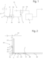
- Annex 20 to Fig.2 is suitable for facilities with limited access to the floor area of the facility. This can be the case, for example, in retail areas, in laboratories or underneath ice and cleaning machines.
- the measuring element 32 of the sensor 32' is preferably positioned at the lowest point of the line section 2.2.
- This system 20 can optionally be built with ventilation.
- the line from the ventilation valve 31 to the measuring element 32 can be laid horizontally or with a slight gradient of, for example, 0.5%.
- the position of the ventilation valve 31 is preferably provided in a drain 28 in the ground 29 for the source 1 with a sieve or similar so that the waste water is sucked out cleanly. Otherwise, the functions of the system 20 correspond to those after Fig.1 and will therefore not be discussed in more detail.
- Annex 30 to Fig.3 is suitable for refrigerated cabinets consisting of several units 1a, 1b, which are provided on the underside with one or more siphon lines 2.5 for collecting the waste water that accumulates therein, which are connected to the line section 2.2 serving as a collecting or through-line below the units 1a, 1b. Because of these siphon lines 2.5, the waste water from the units can flow simultaneously into the waste water line 2. Furthermore, ventilation hoses 2.7 leading into the siphon lines 2.5 are provided, which serve to ensure that the line section 2.2 serving as a collecting line can fill with waste water and the siphon lines 2.5 are not sucked dry during suction, so that they act like a seal and no cold air can be sucked out. Furthermore, a ventilation hose 2.7 is arranged in the line section 2.3 running vertically upwards, as well as the valve element 5. This can ensure sufficient ventilation in the waste water line 2.
- the valve element 5 is opened by the control device for a period of time.
- the ventilation hoses 2.7 help to add air at each connection and, optionally, also at the beginning of the riser.
- a hose can also be used if it cannot lie flat over its entire length due to possible obstacles. This arrangement of system 30 has the advantage in refrigerated cabinets without free space that the pipes are emptied and can therefore be drained with the same drainage cross-section without the formation of deposits.
- Annex 40 to Fig.4 concerns a variant similar to Annex 30 to Fig.3 with at least one facility with a free-standing unit. Its structure corresponds to that of the design according to Fig.3 , with the difference that, due to the lack of a free side wall, the air supply line 2.6 cannot be installed underneath the unit in very low-lying units. For this reason, the air supply line 2.6 is laid in the ground and provided with a non-return valve as a ventilation valve 31 so that, in the case of long lines laid in the ground, the full filling of the line section 2.2 does not impair the extraction.
- the opening in the air supply line 2.6 which may be designed with a ventilation valve or open, enables the waste water line 2 to be drained dry.
- these siphon lines 2.5 are intended to collect the waste water that accumulates in units 1 as sources, and these ventilation hoses 2.7 connected to the siphon lines are also provided.
- these siphon lines and/or ventilation hoses could be dispensed with. and direct pipe connections from the source to the sewer line 2 shall be provided.
- the system can also be centrally controlled electrically, hydraulically and/or pneumatically from this one control device, thus enabling automated operation.
- Suction lines with different internal diameters and/or lengths can be used, thus enabling the disposal of larger quantities of wastewater without the system having to be built accordingly larger.
- the wastewater flowing from the source can be any liquid, such as oil or mixtures of oil, grease, cleaning agents and/or water.
- a vacuum pump for the suction device because it can very efficiently suck the waste water out of the sewer line with or without air, even if it is mixed with clogging contaminants.
- a feed pump of any kind could also be used.
- valve element 5 could be dispensed with and the through-pipe and the riser pipe could be led directly to the vacuum pump.
- a riser pipe is also not absolutely necessary. Depending on the conditions of the cooling units, kitchen appliances, etc., the pipe could be led horizontally or downwards after the waste water pipe.
- the waste water in the waste water pipe could be filled in the pipe section, the pipe section up to the valve element in the pipe section, and only then would the valve element 5 be opened and the waste water sucked out by the vacuum pump.
- the measuring element 32 could be placed in the pipe section 2.3 in front of the valve element.
- each with at least one measuring element and at least one valve element with a central or several vacuum pumps which could be controlled and, if necessary, regulated by one or more control devices.
- control devices can be electrically, hydraulically and/or pneumatically functioning control devices, which can also include at least one control process.
Landscapes
- Engineering & Computer Science (AREA)
- General Engineering & Computer Science (AREA)
- Combustion & Propulsion (AREA)
- Physics & Mathematics (AREA)
- Mechanical Engineering (AREA)
- Thermal Sciences (AREA)
- Chemical & Material Sciences (AREA)
- Health & Medical Sciences (AREA)
- Life Sciences & Earth Sciences (AREA)
- Hydrology & Water Resources (AREA)
- Public Health (AREA)
- Water Supply & Treatment (AREA)
- Jet Pumps And Other Pumps (AREA)
- Sewage (AREA)
Applications Claiming Priority (1)
| Application Number | Priority Date | Filing Date | Title |
|---|---|---|---|
| CH000115/2023A CH720487B1 (de) | 2023-02-09 | 2023-02-09 | Anlage zum Abführen von Abwasser insbesondere durch Vakuumabsaugung |
Publications (2)
| Publication Number | Publication Date |
|---|---|
| EP4414637A1 true EP4414637A1 (fr) | 2024-08-14 |
| EP4414637B1 EP4414637B1 (fr) | 2025-12-24 |
Family
ID=89723191
Family Applications (1)
| Application Number | Title | Priority Date | Filing Date |
|---|---|---|---|
| EP24153966.7A Active EP4414637B1 (fr) | 2023-02-09 | 2024-01-25 | Installation pour l'évacuation d'eaux usées, en particulier par aspiration sous vide |
Country Status (3)
| Country | Link |
|---|---|
| EP (1) | EP4414637B1 (fr) |
| CH (1) | CH720487B1 (fr) |
| FI (1) | FI4414637T3 (fr) |
Citations (5)
| Publication number | Priority date | Publication date | Assignee | Title |
|---|---|---|---|---|
| FR2694927A1 (fr) * | 1992-08-21 | 1994-02-25 | Mc International | Dispositif pour l'acheminement de liquide d'un point bas vers un point haut. |
| EP1085134A2 (fr) | 1999-09-16 | 2001-03-21 | Evac International Oy | Appareil d'aération pour une conduite verticale dans un système d'évacuation à vide |
| EP1130180A2 (fr) * | 2000-02-08 | 2001-09-05 | Evac International Oy | Colonne de décharge des eaux usées |
| EP1172492A2 (fr) * | 2000-07-10 | 2002-01-16 | Evac International Oy | Système à dépression |
| WO2003006892A1 (fr) * | 2001-07-10 | 2003-01-23 | Evac International Oy | Systeme de collecte sous vide |
-
2023
- 2023-02-09 CH CH000115/2023A patent/CH720487B1/de unknown
-
2024
- 2024-01-25 FI FIEP24153966.7T patent/FI4414637T3/fi active
- 2024-01-25 EP EP24153966.7A patent/EP4414637B1/fr active Active
Patent Citations (5)
| Publication number | Priority date | Publication date | Assignee | Title |
|---|---|---|---|---|
| FR2694927A1 (fr) * | 1992-08-21 | 1994-02-25 | Mc International | Dispositif pour l'acheminement de liquide d'un point bas vers un point haut. |
| EP1085134A2 (fr) | 1999-09-16 | 2001-03-21 | Evac International Oy | Appareil d'aération pour une conduite verticale dans un système d'évacuation à vide |
| EP1130180A2 (fr) * | 2000-02-08 | 2001-09-05 | Evac International Oy | Colonne de décharge des eaux usées |
| EP1172492A2 (fr) * | 2000-07-10 | 2002-01-16 | Evac International Oy | Système à dépression |
| WO2003006892A1 (fr) * | 2001-07-10 | 2003-01-23 | Evac International Oy | Systeme de collecte sous vide |
Also Published As
| Publication number | Publication date |
|---|---|
| CH720487A2 (de) | 2024-08-15 |
| CH720487B1 (de) | 2026-01-15 |
| FI4414637T3 (fi) | 2026-03-23 |
| EP4414637B1 (fr) | 2025-12-24 |
Similar Documents
| Publication | Publication Date | Title |
|---|---|---|
| EP4281708B1 (fr) | Appareil de cuisson pour cuisine professionnelle doté d'un dispositif d'aspiration de graisse, et procédé pour faire fonctionner un tel appareil de cuisson à aspiration de graisse | |
| EP1717518B1 (fr) | Four comprenant une ouverture d'évacuation de l'enceinte et un siphon | |
| DE19912444A1 (de) | Vorrichtung zur elektronischen Verkalkungsüberwachung | |
| DE10310486B4 (de) | Obengeführtes Rückflussleitungssystem | |
| DE102005018861B4 (de) | Geschirrspüler und Methode zum Steuern eines Geschirrspülers | |
| DE102005018879B4 (de) | Geschirrspüler | |
| DE2745498A1 (de) | Vorrichtung zur steuerung einer fluessigkeitsbeigabe | |
| EP4414637B1 (fr) | Installation pour l'évacuation d'eaux usées, en particulier par aspiration sous vide | |
| DE102006026817A1 (de) | Gewerbliche Geschirrspülmaschine in Form eines Programmautomaten | |
| DE102011082429B4 (de) | Getränkezubereitungseinrichtung mit separatem Entkalkertank | |
| EP3569134B1 (fr) | Automate de nettoyage et de désinfection | |
| DE2232622C3 (de) | Klosettspülvorrichtung mit Umlauf der Reinigungsflüssigkeit | |
| DE102018204685B4 (de) | Heißgetränkezubereitungsvorrichtung | |
| EP4259873B1 (fr) | Dispositif de filtrage pour un lave-vaisselle ou une machine à laver | |
| DE102019001754A1 (de) | Siphoneinrichtung | |
| EP2664859A2 (fr) | Dispositif de récupération de chaleur et son utilisation | |
| DE102012200227B4 (de) | Wasserversorgungseinheit für eine Geschirrspülmaschine | |
| DE102017212734B4 (de) | Einbaugetränkegerät mit Ablaufeinrichtung | |
| DE102018200744A1 (de) | Brühgetränkegerät mit Ablaufstrang | |
| WO2016135028A1 (fr) | Procédé de nettoyage d'une cloison destinée à un transfert de chaleur dans une unité de récupération de chaleur pour les eaux usées, et unité de récupération de chaleur | |
| DE3346320A1 (de) | Tank zum speichern von brauchwasser fuer eine waermerueckgewinnungsanlage | |
| EP3927663B1 (fr) | Système séparateur de graisse, récipient et procédé | |
| DE10120410A1 (de) | Regenwassernutzungsanlage und Verfahren zu deren Betrieb | |
| DE10210983B4 (de) | Industrielle Reinigungsanlage mit einer Selektionsvorrichtung für gebrauchte Reinigungsflüssigkeiten | |
| DE102011089118A1 (de) | Fluidsammeleinrichtung |
Legal Events
| Date | Code | Title | Description |
|---|---|---|---|
| PUAI | Public reference made under article 153(3) epc to a published international application that has entered the european phase |
Free format text: ORIGINAL CODE: 0009012 |
|
| STAA | Information on the status of an ep patent application or granted ep patent |
Free format text: STATUS: THE APPLICATION HAS BEEN PUBLISHED |
|
| AK | Designated contracting states |
Kind code of ref document: A1 Designated state(s): AL AT BE BG CH CY CZ DE DK EE ES FI FR GB GR HR HU IE IS IT LI LT LU LV MC ME MK MT NL NO PL PT RO RS SE SI SK SM TR |
|
| STAA | Information on the status of an ep patent application or granted ep patent |
Free format text: STATUS: REQUEST FOR EXAMINATION WAS MADE |
|
| 17P | Request for examination filed |
Effective date: 20250129 |
|
| GRAP | Despatch of communication of intention to grant a patent |
Free format text: ORIGINAL CODE: EPIDOSNIGR1 |
|
| STAA | Information on the status of an ep patent application or granted ep patent |
Free format text: STATUS: GRANT OF PATENT IS INTENDED |
|
| GRAS | Grant fee paid |
Free format text: ORIGINAL CODE: EPIDOSNIGR3 |
|
| RIC1 | Information provided on ipc code assigned before grant |
Ipc: F25D 21/14 20060101AFI20251006BHEP Ipc: F25D 17/00 20060101ALI20251006BHEP Ipc: E03F 1/00 20060101ALN20251006BHEP |
|
| GRAA | (expected) grant |
Free format text: ORIGINAL CODE: 0009210 |
|
| STAA | Information on the status of an ep patent application or granted ep patent |
Free format text: STATUS: THE PATENT HAS BEEN GRANTED |
|
| INTG | Intention to grant announced |
Effective date: 20251022 |
|
| AK | Designated contracting states |
Kind code of ref document: B1 Designated state(s): AL AT BE BG CH CY CZ DE DK EE ES FI FR GB GR HR HU IE IS IT LI LT LU LV MC ME MK MT NL NO PL PT RO RS SE SI SK SM TR |
|
| REG | Reference to a national code |
Ref country code: CH Ref legal event code: F10 Free format text: ST27 STATUS EVENT CODE: U-0-0-F10-F00 (AS PROVIDED BY THE NATIONAL OFFICE) Effective date: 20251224 Ref country code: GB Ref legal event code: FG4D Free format text: NOT ENGLISH |
|
| REG | Reference to a national code |
Ref country code: DE Ref legal event code: R096 Ref document number: 502024000531 Country of ref document: DE |
|
| REG | Reference to a national code |
Ref country code: DK Ref legal event code: T3 Effective date: 20260225 |
|
| PGFP | Annual fee paid to national office [announced via postgrant information from national office to epo] |
Ref country code: LU Payment date: 20260204 Year of fee payment: 3 |
|
| REG | Reference to a national code |
Ref country code: FI Ref legal event code: FGE |
|
| P01 | Opt-out of the competence of the unified patent court (upc) registered |
Free format text: CASE NUMBER: UPC_APP_0005637_4414637/2026 Effective date: 20260216 |
|
| REG | Reference to a national code |
Ref country code: NL Ref legal event code: FP |
|
| PGFP | Annual fee paid to national office [announced via postgrant information from national office to epo] |
Ref country code: SE Payment date: 20260212 Year of fee payment: 3 |
|
| REG | Reference to a national code |
Ref country code: GR Ref legal event code: EP Ref document number: 20260400481 Country of ref document: GR Effective date: 20260407 |
|
| PGFP | Annual fee paid to national office [announced via postgrant information from national office to epo] |
Ref country code: ES Payment date: 20260305 Year of fee payment: 3 Ref country code: MC Payment date: 20260217 Year of fee payment: 3 |
|
| REG | Reference to a national code |
Ref country code: LT Ref legal event code: MG9D |
|
| PGFP | Annual fee paid to national office [announced via postgrant information from national office to epo] |
Ref country code: NO Payment date: 20260311 Year of fee payment: 3 Ref country code: DK Payment date: 20260302 Year of fee payment: 3 Ref country code: DE Payment date: 20260217 Year of fee payment: 3 |
|
| PG25 | Lapsed in a contracting state [announced via postgrant information from national office to epo] |
Ref country code: HR Free format text: LAPSE BECAUSE OF FAILURE TO SUBMIT A TRANSLATION OF THE DESCRIPTION OR TO PAY THE FEE WITHIN THE PRESCRIBED TIME-LIMIT Effective date: 20251224 |
|
| PGFP | Annual fee paid to national office [announced via postgrant information from national office to epo] |
Ref country code: AT Payment date: 20260301 Year of fee payment: 3 |
|
| PGFP | Annual fee paid to national office [announced via postgrant information from national office to epo] |
Ref country code: BE Payment date: 20260212 Year of fee payment: 3 Ref country code: FI Payment date: 20260302 Year of fee payment: 3 Ref country code: IT Payment date: 20260131 Year of fee payment: 3 |
|
| PG25 | Lapsed in a contracting state [announced via postgrant information from national office to epo] |
Ref country code: RS Free format text: LAPSE BECAUSE OF FAILURE TO SUBMIT A TRANSLATION OF THE DESCRIPTION OR TO PAY THE FEE WITHIN THE PRESCRIBED TIME-LIMIT Effective date: 20260324 |
|
| PGFP | Annual fee paid to national office [announced via postgrant information from national office to epo] |
Ref country code: FR Payment date: 20260212 Year of fee payment: 3 |
|
| REG | Reference to a national code |
Ref country code: ES Ref legal event code: FG2A Ref document number: 3063920 Country of ref document: ES Kind code of ref document: T3 Effective date: 20260421 |