EP4420846A1 - Guidage de produit avec rouleau de traction - Google Patents
Guidage de produit avec rouleau de traction Download PDFInfo
- Publication number
- EP4420846A1 EP4420846A1 EP23157944.2A EP23157944A EP4420846A1 EP 4420846 A1 EP4420846 A1 EP 4420846A1 EP 23157944 A EP23157944 A EP 23157944A EP 4420846 A1 EP4420846 A1 EP 4420846A1
- Authority
- EP
- European Patent Office
- Prior art keywords
- roller
- product
- traction
- traction roller
- food
- Prior art date
- Legal status (The legal status is an assumption and is not a legal conclusion. Google has not performed a legal analysis and makes no representation as to the accuracy of the status listed.)
- Granted
Links
Images



Classifications
-
- B—PERFORMING OPERATIONS; TRANSPORTING
- B26—HAND CUTTING TOOLS; CUTTING; SEVERING
- B26D—CUTTING; DETAILS COMMON TO MACHINES FOR PERFORATING, PUNCHING, CUTTING-OUT, STAMPING-OUT OR SEVERING
- B26D7/00—Details of apparatus for cutting, cutting-out, stamping-out, punching, perforating, or severing by means other than cutting
- B26D7/06—Arrangements for feeding or delivering work of other than sheet, web, or filamentary form
- B26D7/0683—Arrangements for feeding or delivering work of other than sheet, web, or filamentary form specially adapted for elongated articles
-
- B—PERFORMING OPERATIONS; TRANSPORTING
- B26—HAND CUTTING TOOLS; CUTTING; SEVERING
- B26D—CUTTING; DETAILS COMMON TO MACHINES FOR PERFORATING, PUNCHING, CUTTING-OUT, STAMPING-OUT OR SEVERING
- B26D7/00—Details of apparatus for cutting, cutting-out, stamping-out, punching, perforating, or severing by means other than cutting
- B26D7/06—Arrangements for feeding or delivering work of other than sheet, web, or filamentary form
-
- B—PERFORMING OPERATIONS; TRANSPORTING
- B26—HAND CUTTING TOOLS; CUTTING; SEVERING
- B26D—CUTTING; DETAILS COMMON TO MACHINES FOR PERFORATING, PUNCHING, CUTTING-OUT, STAMPING-OUT OR SEVERING
- B26D7/00—Details of apparatus for cutting, cutting-out, stamping-out, punching, perforating, or severing by means other than cutting
- B26D7/06—Arrangements for feeding or delivering work of other than sheet, web, or filamentary form
- B26D7/0625—Arrangements for feeding or delivering work of other than sheet, web, or filamentary form by endless conveyors, e.g. belts
-
- B—PERFORMING OPERATIONS; TRANSPORTING
- B26—HAND CUTTING TOOLS; CUTTING; SEVERING
- B26D—CUTTING; DETAILS COMMON TO MACHINES FOR PERFORATING, PUNCHING, CUTTING-OUT, STAMPING-OUT OR SEVERING
- B26D2210/00—Machines or methods used for cutting special materials
- B26D2210/02—Machines or methods used for cutting special materials for cutting food products, e.g. food slicers
-
- B—PERFORMING OPERATIONS; TRANSPORTING
- B65—CONVEYING; PACKING; STORING; HANDLING THIN OR FILAMENTARY MATERIAL
- B65G—TRANSPORT OR STORAGE DEVICES, e.g. CONVEYORS FOR LOADING OR TIPPING, SHOP CONVEYOR SYSTEMS OR PNEUMATIC TUBE CONVEYORS
- B65G21/00—Supporting or protective framework or housings for endless load-carriers or traction elements of belt or chain conveyors
- B65G21/20—Means incorporated in, or attached to, framework or housings for guiding load-carriers, traction elements or loads supported on moving surfaces
- B65G21/2045—Mechanical means for guiding or retaining the load on the load-carrying surface
- B65G21/2063—Mechanical means for guiding or retaining the load on the load-carrying surface comprising elements not movable in the direction of load-transport
- B65G21/209—Mechanical means for guiding or retaining the load on the load-carrying surface comprising elements not movable in the direction of load-transport for augmenting or creating a pression force between the load and the load-carrying surface
Definitions
- the present invention relates to a product guide for feeding food products to a slicing unit of a food slicing machine and to a food slicing machine.
- Food products such as sausage, cheese or bread
- a food slicing machine which can be a high-performance slicer, to a slicing unit with a cutting blade, for example with a rotating sickle or circular blade.
- one or more product guides are provided in a feed area, which come into contact with the food bar in order to move it to a cutting plane of the slicing unit.
- the product guide can in particular be designed as an upper product hold-down device, which presses down on the food bar from above.
- the known variants of product management can have disadvantages, especially with regard to product and/or application-specific requirements.
- the object of the invention is to provide an alternative product guidance.
- a food slicing machine in particular a high-performance slicer, one or more food products can be cut into food slices by means of a slicing unit.
- the slicing unit can comprise a rotary and/or planetary rotating cutting blade, in particular a sickle or circular blade.
- a food product can initially be on a single-cycle belt or placed or conveyed onto it.
- a track guide with central separating bars, in particular metal sheets, can be installed above the single-cycle belt, which extend from above to just above the belt surface of the single-cycle belt. The lateral position of these central separating bars can be adjusted to the width of the food product to be sliced.
- the food product can be conveyed from the single-cycle belt onto a product conveyor belt.
- the product conveyor belt that is connected to the infeed belt in the conveying direction can be part of a loading swing and can be pivoted upwards about an axis located on its downstream side.
- the food product can be conveyed horizontally from the infeed belt to the product conveyor belt and the product conveyor belt can then be pivoted upwards in order to feed the food product to the cutting blade in a support plane that is inclined to the horizontal.
- a lateral fixed stop can be provided, the transverse position and longitudinal alignment of which is coordinated with a cutting edge or cutting glasses that interact with the cutting blade when separating the slices from the product.
- a parallel side stop can be arranged on the opposite side. This allows the food product to be guided lengthwise.
- the adjustable side stop can be adjustable in the transverse direction in order to align a product in the transverse direction.
- the product feeds are designed with multiple tracks.
- several side stops can be provided in the area of the product conveyor belt, which can be adjusted laterally to the conveying direction.
- the side stops can be adjustable together.
- a product conveying device in the form of a lower product support can be arranged between the product conveyor belt and the cutting knife, which feeds the food product to the cutting knife.
- the product support can be relatively short compared to the product conveyor belt.
- the product support can reach right up to the cutting edge and thus support the food product up to the cutting edge.
- the product support can support precise product feed into the cutting plane.
- a gripper can be provided which engages with a rear end, in particular an upstream end, of a food product and acts as a product holder when the product is fed to the cutting plane.
- differences in the weight or cross-sectional profile of the products can be compensated and the thickness of the separated product slices for the fed products can be changed independently of one another during slicing in order to be able to individually achieve a predetermined weight of individual product slices or the weight of portions from several slices.
- a distance can be created from the cutting blade for empty cuts.
- one gripper can be provided per conveyor track and the grippers can be attached to a common feed unit and can be extended in the conveying direction and retracted against the conveying direction independently of one another relative to the feed unit.
- An upper product guide can be provided which presses on the food product from above in the form of a product hold-down device in order to support the feed.
- the food slices separated from the food product by the cutting blade can fall onto a portioning unit, in particular a portioning belt.
- the portioning unit can be adjustable so that a portion, in particular a stack of food slices, can be created with a defined size and arrangement.
- the portioning unit, in particular a conveyor or support surface of the portioning unit can be height-adjustable in order to ensure that the slices fall along a constant path.
- the portioning unit or The support surface can be moved in the conveying direction or sideways, or both, in order to create defined stack shapes, such as a shingled arrangement. Once a complete portion has been created, it can be conveyed away using the support surface.
- separator sheets can be automatically inserted between the food slices on the portioning unit using a separator sheet inserter, also called an "interleaver".
- multi-track food slicing machines With multi-track food slicing machines, several food products can be sliced in parallel.
- the elements contributing to the product feed can be controlled individually for each track.
- the food products can be fed to the cutting blade at different speeds.
- the invention relates to a product guide for feeding food products to a slicing unit of a food slicing machine.
- the product guide comprises a traction roller which is designed to come into conveying contact with a food product and to contribute to feeding the food product to the slicing unit.
- the product guide further comprises a carrier, wherein the carrier can be arranged pivotably about a first axis, and a drive means configured to rotate the traction roller about a second axis.
- the traction roller is arranged on the carrier and the first axis is spaced from the second axis.
- the carrier can be arranged to pivot about a first horizontal axis.
- the product guide can adjust its orientation to the size, especially the height, of the food product.
- the traction roller can be positioned close to the slicing unit.
- the contact pressure can be adjusted to the type or condition of the food product, for example the flexibility and surface finish. For bars of a softer food product, a lower contact pressure can be set than for bars of a harder food product. This does not affect the structure of the food product, but ensures precise feeding.
- the carrier can be designed to pivot during operation. This allows a contact pressure to be varied.
- the product guide can be adjusted to the size, in particular the height, of the food product. The adjustment can be made before the actual production operation.
- the carrier can be designed to pivot vertically during operation, in particular vertically within a limited area. When the food product is moved into the effective range of the product guide, the latter can automatically follow the contour of the food product, in particular from a lower position which is below the upper edge of the product, swing upwards to come into contact with the top of the food product.
- the product guide can be an upper product guide, in particular a product hold-down device.
- the traction roller can come into contact with the top of the food product, in particular the food bar. This can achieve a certain clamping effect, so that a more precise product feed can be ensured than in comparison to a pure feed through a lower product support.
- the upper product guide, in particular the traction roller can be actively pressed onto the food product from above. In particular, it can be actively pressed with a defined contact pressure. The food product can be clamped between the upper product guide and the lower product support.
- the first axis and the second axis can be offset from one another in the conveying direction. Such an arrangement of the first and second axis can enable adaptation to different product heights.
- the product guide, in particular the carrier, can be arranged in the form of a swing arm or a pivoting arm.
- the contact pressure can also be adjusted.
- the first axis can be in an upstream half of the carrier and the second axis in a downstream half of the carrier.
- the food bar can be moved into or under the product guide, whereby the traction roller can have an initial position at least partially below the height of the food bar and can automatically pivot upwards by contact with the food bar, which can have a slightly smaller cross-section or a dome at the front end.
- a downward bias of the product guide can also be set.
- a corresponding spring can be arranged on the carrier.
- an active pressing mechanism for example by means of pneumatics, can be provided.
- the product guide can be part of a feed device associated with a lower product support.
- the feed speed of the upper product guide and the lower product support can be coordinated, in particular synchronized.
- a height adjustment for the upper product guide and/or lower product support can be provided. This allows an adjustment or adaptation to be made with regard to the height of the food product and the pre-tension required for good traction. Additionally or alternatively, the height adjustment can be used to align the food product with a cutting edge of the slicing unit.
- the drive means can be a rotating drive means.
- a force for rotating the traction roller can be transmitted to it, whereby the force can be sufficiently large to move food products even with greater Density or weight can be precisely fed to the slicing unit.
- the drive using a rotating drive means can be low-wear.
- the drive means can be a rotating drive belt.
- the rotating drive belt can be a toothed belt. This allows precise rotation of the traction roller and thus precise advancement of the food product.
- the toothed belt can engage with corresponding teeth arranged on the traction roller. Power transmission by means of drive belts, in particular toothed belts, can represent a low-maintenance, precise and stable drive.
- the traction roller can be connected to a drive shaft via the rotating drive means in order to be driven by the drive shaft.
- the drive shaft can be spaced apart from the traction roller.
- a drive motor connected to the drive shaft and optionally a gear can be arranged at a distance from the traction roller.
- the drive shaft, drive motor and gear can thus be arranged further away from a cutting plane of the slicing unit than the traction roller, or the traction roller can be positioned closer to the cutting plane.
- the drive shaft can be arranged separately from the pivotable carrier in the food slicing machine, in particular starting from a housing of the food slicing machine.
- the drive shaft can be arranged offset from the traction roller in the conveying direction.
- the drive shaft can be arranged upstream of the traction roller and thus further away from the slicing unit than the traction roller.
- a drive roller is arranged on the carrier, and a first drive means rotates around the traction roller and the drive roller, and a second drive means rotates around the drive roller and a drive shaft.
- the first drive means can thus be individually adapted to the carrier geometry and the arrangement of the traction roller, whereas the second drive means can be provided in a standard size.
- the product guide can thus be adapted to different food products with reduced modification effort.
- the traction roller is decoupled from the drive shaft and the drive means can experience less wear and the drive can have improved stability.
- elongation can have a less severe effect with two shorter drive belts than with a single, long drive belt.
- cleaning can be simplified because only the first drive means rotating around the traction roller comes close to the food product.
- the drive roller can have two essentially separate rollers, which are connected by means of a rigid axle.
- the first and the second drive means can each rotate over one of these rollers.
- the rollers can each be equipped, for example by means of lateral elevations or flanges, that a lateral displacement of the drive means is prevented. This allows the drive means to rotate stably and at a distance from each other.
- the two separate rollers of the drive roller can have a different diameter. This allows a transmission ratio between the first and the second drive means to be defined.
- the drive means can be a drive shaft arranged coaxially on the traction roller. Thus, there is no need to drive the traction roller with a rotating drive means, such as a drive belt.
- the power transmission to the traction roller and thus the drive can be carried out by means of a cardan shaft, or a universal joint shaft, or two bevel gear sets, or combinations thereof.
- the traction roller can be coaxially connected to a drive motor or a motor gearbox in order to be driven by it.
- a drive shaft can be arranged between the drive motor and the traction roller or between the motor gearbox and the traction roller.
- a drive motor can be arranged directly in the traction roller to drive the traction roller.
- a drum motor can be integrated into the traction roller. This allows a particularly compact product guide to be achieved.
- the traction roller can be movably mounted on the carrier.
- the traction roller can be rotatably mounted on the carrier.
- the traction roller can be mounted between two side struts of the carrier.
- the distance between the side struts can essentially correspond to a conveyor track width, in particular at most one conveyor track width.
- the distance between the side struts can essentially correspond to a product width, in particular at most one product width.
- the width across all components of a product guide can essentially correspond to a conveyor track width or product width, in particular at most one conveyor track width or product width. All components of a product guide, in particular of a carrier, can be arranged within a conveyor track.
- Several product guides, preferably two, can be arranged within a conveyor track, in particular in order to influence particularly wide products. These product guides can act on a product synchronously or independently.
- the traction roller comprises a first circumferential region and a second circumferential region, wherein the drive means rotates around the second circumferential region, wherein the diameter of the second circumferential region and of the drive means resting thereon is smaller than the diameter of the first circumferential region.
- the drive means rotates around the second circumferential region, wherein the diameter of the second circumferential region and of the drive means resting thereon is smaller than the diameter of the first circumferential region.
- the second, smaller diameter circumferential region can be arranged at a lateral end of the traction roller.
- the second circumferential region can be arranged at a left or right lateral end of the traction roller as seen in the conveying direction.
- the second peripheral area can be arranged at a lateral end of the traction roller on an operating side of the product guide. This makes the drive means easily accessible and particularly easy to remove for cleaning.
- the second circumferential area can be provided between a first circumferential area arranged laterally, to the left and right as seen in a conveying direction. This makes it possible to transmit power centrally and axially symmetrically, which can prevent one-sided loading of the traction roller bearing.
- the traction roller preferably has a surface structure on its outer circumference with a height of less than approximately 3 millimeters to 4 millimeters, preferably less than approximately 2 millimeters. This can enable at least partial positive engagement with the material of the food product, i.e. deformation of the same. In this way, a force for moving the food product can be transferred to it more advantageously. On the other hand, damage to the food product due to surface structures that protrude too far can be avoided. In particular, tearing of the surface of the food product can be avoided, which is particularly relevant for softer food products.
- the traction roller can have transverse grooves.
- the transverse grooves can be rectangular or tapered elevations, i.e. outer edges, which extend transversely to the conveying direction along the traction roller.
- the transverse grooves can cause a corresponding deformation of the surface of the food product, so that in addition to a force-fitting propulsion of the food product, a form-fitting component can be added.
- the traction roller can have knobs. This allows the traction roller to engage more deeply in the material of the food product and increases the positive component of the force transmission.
- the traction roller can have a wave shape or a bump shape on its surface. These can ensure that the surface of the food product is only pressed lightly and therefore gently.
- the traction roller can have spikes.
- Spikes can be protruding structures similar to knobs, but which are pointed. This allows heavy and solid food products, especially those with high density, to be fed forward in a stable manner.
- the spikes can be inclined in the conveying direction.
- the spikes can be arranged or inclined in such a way that they are inclined in the conveying direction on the side of the traction roller that is in contact with the food product. This can further increase the power transmission into the food product.
- the outer circumference of the traction roller can be made of stainless steel, especially rust-proof stainless steel. This makes the traction roller suitable for use in the food industry and easy to clean. In addition, stainless steel can increase longevity due to low wear.
- the outer circumference of the traction roller can include an elastomer. This allows the food product to be transported gently.
- an elastomer can be selected that has an increased coefficient of static friction, which improves power transmission.
- the outer circumference of the traction roller or the entire roller can comprise a plastic, in particular one with food approval. This can be easy to clean and can have advantageous static friction and/or elasticity.
- a second traction roller is arranged on the carrier so as to be rotatable about a third axis, the third axis being arranged parallel to and spaced apart in the conveying direction from the second axis of the first traction roller.
- the first and second traction rollers can contribute to the advance of the food product. This can enable increased force transmission to the food product. The increased force transmission and the larger contact area can ensure particularly precise and stable advance of the food product.
- the first and second traction rollers can be arranged one after the other along the conveying direction.
- the first and second traction rollers can be arranged at a distance of a few millimeters or a few centimeters from each other.
- the first and second traction rollers can be arranged further apart from each other, for example at a distance of 10 centimeters to 20 centimeters.
- the first and second traction rollers can be arranged in a downstream half, in particular on a downstream side, of the product guide.
- the first traction roller can be arranged in a downstream half, in particular on a downstream side, of the product guide and the second traction roller can be arranged centrally or in an upstream half of the product guide.
- the first drive means is arranged to drive the first and second traction rollers.
- the traction rollers can thus move synchronously and a single drive shaft can be sufficient to drive both traction rollers.
- the material expenditure and space requirements can be reduced.
- the effort for cleaning can be reduced since only one drive means has to be removed if it requires cleaning.
- the first and second traction rollers can be arranged as part of a rocker or a pendulum.
- the traction rollers can be designed to follow a contour of the food product. This can enable improved contact with the surface of the food product.
- the rocker can have a rotation axis which is arranged in the conveying direction between the first and the second traction roller, in particular between the first and the second traction roller and offset in height.
- the drive roller can be arranged concentrically around the axis of rotation of the seesaw and a rotating drive means can rotate around the drive roller and the first and second traction rollers in order to drive the first and second traction rollers. In this way, the distance between the first traction roller or the second traction roller and the drive roller remains constant even when the seesaw or the pendulum rotates or pivots.
- the carrier can comprise one or more tension rollers which tension the rotating drive means.
- the tension roller can be arranged rigidly on the carrier in the form of a deflection roller.
- the tension roller can keep the rotating drive means under pre-tension.
- the tension roller can be arranged to be movable, for example by means of a spring mechanism. In this way, an elongation of the drive means can be compensated.
- the carrier comprises first and second traction rollers and a tension roller, the tension roller being arranged substantially between the first and second traction rollers.
- the tension roller can help to ensure that the rotating drive means engages the traction rollers with sufficient tension.
- the first rotating drive means can rotate around the tension pulley between the first and second traction pulleys.
- the rotating drive means can rotate around the first traction pulley, then around the tension pulley and then around the second traction pulley.
- the rotating drive means can engage the first and second traction pulleys by means of a first side and engage the tension pulley by means of a second side.
- the tensioning roller can be arranged at a different height from the first and second traction rollers. In this way, tensioning of the drive means can be achieved, while at the same time the first and second traction rollers and the tensioning roller are arranged in a space-saving manner.
- the carrier can have a first and a second traction roller and three tension rollers, which are arranged so that the drive means rotates alternately around a tension roller and a traction roller.
- the rotating drive means can thus be held under tension against the respective traction roller on both sides of each of the two traction rollers.
- the three tension rollers can be arranged at a height offset from the rotation axes of the traction rollers.
- One or more free-running pressure rollers can be arranged on the carrier. These can be brought into contact with the food product using contact pressure.
- the contact of the pressure rollers with the food product can occur at the same time as or at a different time than the contact of the traction rollers with the food product. The latter can occur, for example, while the product guide or the carrier is approaching the food product.
- the one or more pressure rollers can stabilize the feed movement of the food product in addition to the traction rollers.
- one or more free-running pressure rollers are arranged downstream of the traction roller.
- one or more free-running pressure rollers are arranged downstream of the traction roller in the conveying direction.
- the pressure roller can be arranged offset from the traction roller in the direction of a cutting plane of the slicing unit.
- the pressure roller can be positioned closer to the cutting plane of the slicing unit than the traction roller.
- the pressure roller can have a smaller diameter than the traction roller and can thus be positioned closer to the cutting plane of the slicing unit.
- the one or more free-running pressure rollers can be arranged at an end of the carrier remote from a suspension of the carrier.
- a free-running pressure roller is spring-mounted in order to be elastically pressed against a food product.
- a free-running pressure roller is arranged downstream of the traction roller and spring-mounted in order to be elastically pressed against a food product. In this way, excessive contact pressure can be avoided.
- a free-running pressure roller can be spring-mounted downstream of the traction roller by means of a lever arm.
- the free-running spring-mounted pressure roller can be arranged at a downstream end of the carrier. Due to the lever arm, the spring mechanism can be provided upstream of the pressure roller so that the pressure roller can be moved as close as possible to a cutting plane without the spring mechanism hindering the positioning of the pressure roller. In particular, the space above the pressure roller can remain free due to the lever arm.
- the lever arm can be mounted so that it can rotate or pivot around the second axis. This means that no additional axis of rotation or bearing is required.
- the pressure roller can be mounted downstream and the spring mechanism is provided upstream of the traction roller. This allows the available space on the carrier or in the product guide to be used to advantage.
- the lever arm can be aligned essentially longitudinally. This means that the carrier and the product guide, particularly in the front area, can continue to be flat.
- One or more free-running pressure rollers can be arranged upstream of the traction roller, in particular towards a product feed side or product loading side. In this way, additional pressure points can be created, which can further improve the stability of the feed.
- At least one free-running pressure roller can be arranged downstream and one pressure roller upstream of the traction roller.
- one or more free-running pressure rollers are arranged on the carrier so that they can swing on a common axis of rotation. This allows the contour of the food product to be followed and thus stable contact between the pressure roller and the food product can be maintained in an improved manner.
- one pressure roller is arranged downstream and one pressure roller upstream of the traction roller on a rocker that can rotate about the second axis.
- one pressure roller is arranged in front of the traction roller in the conveying direction and one pressure roller is arranged after the traction roller on a rocker that can rotate about the second axis.
- one pressure roller is arranged downstream and one pressure roller upstream of the traction roller on a rocker that can rotate about the second axis and is assigned to the traction roller. In this way, the contour of the food product can be followed by means of the rocker.
- a corresponding rocker can be present on one traction roller, on several or on all traction rollers or can be assigned to the respective traction roller.
- the rocker can have one or two lateral struts on which the pressure rollers are mounted, and the struts can in turn be mounted on the axis of the traction roller.
- one of the pressure rollers can be pivoted away from the conveying direction in such a way that the respective pressure roller does not come into contact with a conveyed food product.
- the rotating drive means can be guided over a tension roller and the traction roller in such a way that it runs outside the range of movement of the rocker.
- the carrier can have a support element which is configured to come into sliding contact with the food product. This makes it possible to provide an additional element for product guidance using particularly simple structural means.
- the support element can be arranged on the carrier so that it can pivot on a rotation axis. This allows it to follow the contour of the food product.
- the carrier can have a base element, in particular a base plate, wherein the base element has at least one recess through which one or more traction rollers pass at least partially. In this way, the remaining area of the carrier, which is covered from below by the base element, can be protected from dirt.
- the base element can serve as a support element.
- the carrier can have a flat side element, in particular a side plate, on a lateral left side or lateral right side or on both sides.
- the side element can protect the inner elements of the carrier or the product guide from dirt.
- the side elements can be used to store the rolls.
- the side elements can give the carrier stability.
- the carrier can comprise a spring tensioner connected to a tensioning roller, which is configured to tension a rotating drive means.
- the tensioning roller can be mounted so that it can move, in particular be displaced.
- the spring tensioner can press the tensioning roller with a constant force against the rotating drive means so that the latter is kept at a constant tension.
- an elongation of the drive means i.e. a lengthening, can be compensated in this way.
- the spring tensioner can be arranged to tension a rotating drive means which rotates via a drive shaft. This can ensure reliable power transmission to the traction roller.
- the carrier can comprise a pneumatic tensioner connected to a tension roller, which is configured to tension a rotating drive means.
- the pneumatic tensioner can be set up to build up or maintain a defined pressure. In particular, higher pressures and thus higher clamping forces can be achieved than, for example, using purely mechanical clamping devices. In this way, the rotating drive means can be tensioned particularly reliably, even with higher clamping forces.
- a pneumatic control can be configured to regulate or adjust the clamping force, or both.
- the pneumatic tensioner can be arranged to tension a rotating drive means which rotates via a drive shaft.
- the rotating drive means can be reliably kept under tension and the traction roller can be driven accordingly reliably.
- the pneumatic tensioner may comprise a second tension roller which is arranged coaxially about a fourth axis, and wherein the rotating drive means rotates about the first and second tension rollers and the pneumatic tensioner is configured to pivot the first tension roller about the fourth axis by means of a pneumatic piston in order to tension or relax the drive means.
- This may involve the driving means being pulled onto the rollers of the carrier simplify, as the drive means can be placed over the rollers without tension and the first tension roller can then be pivoted so that the desired tension of the drive means is achieved. Likewise, when removing the drive means, it can be relaxed before being pulled off.
- the first and second tension rollers of the pneumatic tensioner can be connected by means of a frame part.
- the pneumatic piston can be hinged to the frame part.
- the pneumatic piston can be arranged centrally and twisting or twisting of the first tension roller when it is moved can be avoided.
- the pneumatic piston can be hinged to the frame part by means of a cross strut.
- a strut can be hinged to the first tension roller and the strut can be mounted in a side profile so that it can move using a roller. This guides the pivoting movement and can therefore be additionally stabilized.
- the invention relates to a food slicing machine comprising a slicing unit and a product guide according to one of the embodiments described above and a holding element, wherein the carrier is arranged on the holding element so as to be detachable and pivotable about the first axis.
- the carrier is arranged on the holding element so as to be detachable and pivotable about the first axis.
- the product guide can be brought into contact with the food product with adjustable pressure.
- the holding element can serve as a bearing and represent or have the pivot axis.
- the holding element can be a strut that runs transversely to the conveying direction. This allows the product guide to pivot around the strut.
- the carrier can be plugged onto the holding element.
- the carrier can be pushed onto the holding element.
- the carrier or the product guide can be removed for cleaning work.
- two or more product guides can be arranged detachably on the holding element.
- One product guide can be provided per conveyor track.
- the number of conveyor tracks of the food slicing machine can be variable.
- a number of product guides corresponding to the conveyor tracks can be arranged on the holding element.
- the food slicing machine can be designed for a variable and selectable number of one to four conveyor tracks.
- the carrier can be fixable, in particular lockable, to the holding element.
- the food slicing machine can include a pneumatic piston for pivoting the carrier.
- the carrier and thus the traction roller can be brought into contact with a food product in a controllable manner and with a defined contact pressure.
- the product guide can be an upper product guide.
- the traction roller can be pressed onto the food product from above.
- the product guide may be an upper product guide and the food slicing machine may further comprise a lower product support.
- the upper product guide and the lower product support may cooperate to feed the food product to the slicing unit.
- the lower product support can comprise a sliding surface, a conveying surface or a support roller or a roller conveyor or a driven traction roller or a belt conveyor or combinations thereof.
- Active elements that generate the feed as well as passive elements that serve in particular for guidance or support can be provided in both the upper product guide and the lower product support.
- the product guide can be an upper product guide and the food slicing machine can further comprise a lower product support, wherein a traction roller of the upper product guide can be assigned to a traction roller or a support roller of the lower product support.
- a traction roller of the upper product guide can be opposite a traction roller or a support roller of the lower product support substantially perpendicular to the conveying direction.
- Two upper traction rollers can be positioned opposite a lower support roller or traction roller, essentially perpendicular to the conveying direction and in the middle.
- the upper traction roller can also be positioned slightly diagonally opposite the lower traction or support roller.
- the food product can be clamped between the rollers or guided along the feed path.
- the upper product guide can comprise a traction roller and a pressure roller and the lower product support can comprise a traction roller and a support roller, and one of the upper traction roller and pressure roller can be assigned to one of the lower traction roller and support roller, in particular one of the upper traction roller and pressure roller can be positioned opposite one of the lower traction roller and support roller essentially perpendicular to the conveying direction.
- the food product can thus be clamped with two support points at the top and bottom. This allows a particularly stable feed to be achieved and vertical bending of the food product can be avoided.
- the upper product guide and the lower product support can each comprise two traction rollers, with one of the upper traction rollers being opposite one of the lower traction rollers essentially perpendicular to the conveying direction.
- Two or more product guides can be arranged on the holding element.
- Two or more product guides can be provided for a conveyor track, and thus in particular for the advancement of a food product.
- two product guides can act together on a flat food product by the two Product guides in a conveyor track are arranged and operated together, in particular in parallel.
- the two or more product guides can form a corresponding number of conveyor tracks.
- the number of conveyor tracks and thus the number of product guides can be variable.
- the food machine can be designed to operate with one to four conveyor tracks.
- the invention relates to a food slicing machine comprising a slicing unit, a holding element and a carrier, wherein the carrier is detachably arranged on the holding element and pivotable about a first axis, wherein a pressure roller is arranged on the carrier so as to be rotatable about a second axis, wherein the first axis is spaced from the second axis and the pressure roller is designed to come into conveying contact with a food product, wherein the second axis of the pressure roller is spaced less than 250 millimeters from a cutting plane of the slicing unit.
- the second axis of the pressure roller can be spaced less than 200 millimeters, in particular less than 100 millimeters, in particular less than 50 millimeters, from the cutting plane of the slicing unit.
- Two or more pressure rollers can be arranged on the carrier.
- the pressure rollers can be arranged one behind the other in the conveying direction, i.e. along the conveying direction.
- the distances mentioned above refer to the most downstream pressure roller, i.e. the pressure roller that is arranged closest to the cutting plane.
- the two or more pressure rollers can be arranged as part of a pendulum or a rocker so that they can pivot together on the carrier, with the axis of rotation of the pendulum or the rocker being oriented transversely to the conveying direction. This allows the contour of the food product to be followed, especially when it is moved under the product guide.
- the most upstream pressure roller can be arranged vertically upwards. This can make it easier to insert the food product under the product guide.
- the Product guide can be lifted through the food product to then automatically follow the upper contour of the food product.
- the two or more pressure rollers can each be arranged on the support so that they can pivot individually on a rotation axis. This allows unevenness to be compensated.
- the invention relates to a food slicing machine comprising a slicing unit, a holding element and a carrier, wherein the carrier is arranged detachably and pivotably about a first axis on the holding element, and wherein two or more pressure rollers are arranged as part of a pendulum or a rocker jointly pivotably about a second axis on the carrier, wherein the second axis is spaced from the first axis.
- the pressure rollers can be designed to come into conveying contact with a food product.
- All non-driven rollers shown that come into contact with the food product can alternatively be designed as sliding surfaces.
- FIG. 1 shows a perspective view of a food processing line 1 with several processing stations along a conveying direction 500.
- a food block 3 for example, a block of cheese
- a block divider 5 in order to be divided, for example, into four elongated food products, each of which has a smaller height and width than the original food block 3.
- the food products are then analyzed in a scanner 7, for example an X-ray scanner.
- a scanner 7 for example an X-ray scanner.
- the external dimensions of the food products can be recorded or their internal density structure can be determined, or both.
- the subsequent food slicing machine 9 the food products are cut into food slices by means of a slicing unit 11.
- separating sheets can be inserted between the slices by means of a separating sheet inserter 13, also called an "interleaver".
- a continuous checkweigher 17 checks the portion weight.
- a desired number of food portions can be lined up on a subsequent buffer 19 in order to then process portion groups or format sets in the further stations.
- the food portions are placed in packaging trays, for example using a picking robot or a belt conveyor.
- the packaging trays filled with food portions are closed, for example sealed. The closed packages are then labeled and separated.
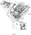
- FIG. 2 shows a perspective view of a section of the food slicing machine 9 with slicing unit 11.
- a product conveyor belt 25 can be pivoted from a lower horizontal position into the inclined position shown and conveys a food product (not shown) to a lower product conveyor device 27 or product support 27, which in turn feeds the food product to the slicing unit 11, where it is sliced at a cutting edge 29 by means of a rotating knife (not shown for the sake of clarity).
- the knife is mounted interchangeably on a knife holder 31 and is set in rotation by this.
- the cutting edge of the knife runs directly in front of the cutting edge 29 and thus defines a cutting plane 33.
- the product support 27 in this embodiment comprises four conveyor tracks, each with five support rollers 35 and a driven traction roller 37.
- a product guide 39 is arranged to come into contact with the food product from above and to help feed the food product to the slicing unit 11.
- the product guide 39 has a carrier 41 which is arranged pivotably about a first axis 100 on a holding element 43 in the form of a cross strut.
- the product guide 39 has a traction roller 37 which comes into conveying contact with the food product by pressing the product guide 39 onto the food product from above.
- a Pneumatic cylinder 45 is connected to the carrier 43 by means of a pneumatic piston 47.
- the traction roller 37 of the product guide 39 is mounted so as to be rotatable about a second axis 200.
- a first drive means 49 rotates around a section of the traction roller 37 and a drive roller 51.
- a second drive means 53 rotates around the drive roller 51 and a drive shaft 55 in order to transfer the rotation of the drive shaft 55 to the drive roller 51 and thus to the traction roller 37.
- the drive shaft 55 is in turn driven by a drive motor, which is installed here invisibly under the cover 57.
- a drive motor which is installed here invisibly under the cover 57.
- the product guides 39 are designed here by way of example in different variants, wherein the first product guide 39 facing the viewer is a product guide 39 according to the invention of a first embodiment.
- FIG 3 shows a perspective view of a second embodiment of a product guide 39, which is slightly different from the first embodiment of Figure 2
- the traction roller 37 is again driven by a first drive means 49, whereby the first drive means 49 rotates around the drive roller 51.
- the drive roller 51 is in turn driven by a drive shaft 55 (see Figure 2 ).
- the drive roller 51 essentially has two separate rollers which are connected by means of a rigid axle 59.
- the drive means 49, 53 are guided on the drive roller 51 by means of lateral disk segments 61.
- tension rollers 63 redirect the drive means 49, 53 and keep them under tension.
- the traction roller 37 is mounted between two side struts 65 so that it can rotate about the second axis 200.
- the traction roller 37 has a surface structure in the form of a tapered, triangular transverse groove.
- a free-running pressure roller 67 is arranged, which is spring-mounted by means of a lever arm 69.
- the lever arm 69 is mounted so that it can rotate about the second axis 200 and is connected to a spring element 71, which generates the pre-tension downwards in the direction of the food product.
- the carrier 41 has a recess 73 in each of the side struts 65, with which the carrier 41 can be placed on the holding element 43 (see Figure 2 ) can be pushed on.
- a fold-away locking mechanism 75 serves to fix the carrier 41 on the holding element 43.
- FIG 4 shows a perspective sectional view of a third embodiment of a product guide 39 with two traction rollers 37 and a pressure roller 67.
- the traction rollers 37 partially pass through recesses 77 of a base element 79 of the carrier 41 in order to come into contact with the food product, whereby the rest of the carrier 41 due to of the floor element 79 is protected from contamination.
- the traction rollers 37 are driven in this embodiment by a single first drive means 49, wherein the drive means 49 is directly connected to a drive shaft 55 (shown in Figure 2 ) of the food slicing machine 9.
- the traction rollers 37 are mounted on the carrier 41 so as to be rotatable about the second axis 200 or the third axis 300.
- the drive means 49 runs over several tension rollers 63, with one tension roller 63 being arranged between the first and second traction roller 37 and slightly offset in height.
- the drive means 49 thus runs alternately around the traction rollers 37 and the tension rollers 63.
- the traction rollers 37 have a first circumferential region 81 and a second circumferential region 83, with the drive means 49 rotating around the second, smaller-diameter circumferential region 83.
- the diameter of the second circumferential region 83 including the drive means 49 resting on it is smaller than the diameter of the first circumferential region 81.
- the food product therefore does not come into contact with the drive means 49.
- the second circumferential region 83 is arranged at a lateral end of the traction roller 37 on an operating side of the product guide 39, i.e. on the side of the food slicing machine 9 from which the product guides 39 can be removed from the holding element 43.
- a tension roller 63 is mounted on a spring tensioner 85 to tension the drive means 49.
- Figure 5 shows a perspective sectional view of a fourth embodiment of a product guide 39 with a traction roller 37 and a first drive means 49 and a second drive means 53, which rotate around the drive roller 51.
- a pressure roller 67 is arranged, which are connected by means of the lever arm 69, wherein the lever arm 69 is mounted so as to be able to swing or rotate about the second axis 200, so that the pressure rollers 67 connected via the lever arm 69 form a rocker 87. Since the representation of Figure 5 is a sectional view, only the rear side strut 65 can be seen, but on the side facing the viewer, i.e.
- Figure 6 shows a perspective view of a fifth embodiment of a product guide 39 with two traction rollers 37, which are driven by a drive means 49, wherein the drive means 49 is directly connected to a drive shaft 55 (not shown here) is connected.
- the product guide 39 has a pneumatic tensioner 91 which comprises a first tension roller 63 and a second tension roller 95 or is connected to these in order to tension the drive means 49.
- the second tension roller 95 is arranged coaxially so as to be rotatable about a fourth axis 400.
- the pneumatic tensioner 91 has a pneumatic piston 47 which rotates the first tension roller 63 about the fourth axis 400, namely the axis of rotation of the second tension roller 95.
- the first tension roller 63 of the pneumatic tensioner 91 is rotated clockwise about the second tension roller 95 in this view in order to tension the drive means 49.
- the first tension roller 63 of the pneumatic tensioner 91 is rotated counterclockwise about the second tension roller 95 in order to relax the drive means 49.
- the first and second tension rollers 63, 95 of the pneumatic tensioner 91 are connected by means of a frame part 97.
- a strut 99 is hinged to the first tension roller 63 to the left and right of the pneumatic piston 47 and the struts 99 are each mounted in a side profile 103 so that they can be moved by means of a roller 101.
- Figure 7 shows a perspective view from below of a sixth embodiment of a product guide 39, in which five free-running pressure rollers 67 are arranged in a rocker 87, the rocker 87 being pivotably mounted about the second axis 200.
- the most upstream pressure roller 67 is arranged offset upwards in the rocker 87. This makes it easier to follow the contour of the food product, particularly when it runs under the product guide 39.
- the carrier 41 has a support element 105 as part of the base element 79, the support element 105 being able to come into sliding contact with the food product.
- the support element 105 also has two bevels 107 for sliding onto the food product.
- a guide 109 in which a lateral bolt of the rocker 87 engages in a groove of a side strut 65 of the carrier 41, serves to guide and as a stop for pivoting the rocker 87.
- Figure 8 shows a schematic view of a combination of upper product guide 39 and lower product support 27 between which a food product 111 is conveyed in the conveying direction 500 to a cutting plane 33.
- the lower product support 27 comprises a support roller 35 and a traction roller 37.
- the upper product guide 39 comprises a traction roller 37 and a pressure roller 67, which are each assigned to the rollers 35, 37 of the product support 27.
- the traction roller 37 of the upper product guide 39 is essentially perpendicular to the conveying direction 500 of the lower support roller 35 and the upper pressure roller 67 is essentially perpendicular to the lower traction roller 37. Conveying direction 500.
- the imaginary connecting line of the centers of the upper traction roller 37 and the lower support roller 35 thus forms a right angle with the conveying direction 500.
- the imaginary connecting line of the centers of the upper pressure roller 67 and the lower traction roller 37 forms a right angle with the conveying direction 500.
Landscapes
- Life Sciences & Earth Sciences (AREA)
- Forests & Forestry (AREA)
- Engineering & Computer Science (AREA)
- Mechanical Engineering (AREA)
- General Preparation And Processing Of Foods (AREA)
- Details Of Cutting Devices (AREA)
- Structure Of Belt Conveyors (AREA)
Priority Applications (6)
| Application Number | Priority Date | Filing Date | Title |
|---|---|---|---|
| PL23157944.2T PL4420846T3 (pl) | 2023-02-22 | 2023-02-22 | Prowadnica produktu z rolką trakcyjną |
| EP23157944.2A EP4420846B1 (fr) | 2023-02-22 | 2023-02-22 | Guidage de produit avec rouleau de traction |
| ES23157944T ES3016460T3 (en) | 2023-02-22 | 2023-02-22 | Product guide with traction roller |
| PCT/EP2024/054551 WO2024175730A1 (fr) | 2023-02-22 | 2024-02-22 | Guide de produit avec rouleau de traction |
| CN202480014182.XA CN120752119A (zh) | 2023-02-22 | 2024-02-22 | 具有牵引辊的产品引导件 |
| EP24708689.5A EP4669501A1 (fr) | 2023-02-22 | 2024-02-22 | Guide de produit avec rouleau de traction |
Applications Claiming Priority (1)
| Application Number | Priority Date | Filing Date | Title |
|---|---|---|---|
| EP23157944.2A EP4420846B1 (fr) | 2023-02-22 | 2023-02-22 | Guidage de produit avec rouleau de traction |
Publications (2)
| Publication Number | Publication Date |
|---|---|
| EP4420846A1 true EP4420846A1 (fr) | 2024-08-28 |
| EP4420846B1 EP4420846B1 (fr) | 2025-01-22 |
Family
ID=85328797
Family Applications (2)
| Application Number | Title | Priority Date | Filing Date |
|---|---|---|---|
| EP23157944.2A Active EP4420846B1 (fr) | 2023-02-22 | 2023-02-22 | Guidage de produit avec rouleau de traction |
| EP24708689.5A Pending EP4669501A1 (fr) | 2023-02-22 | 2024-02-22 | Guide de produit avec rouleau de traction |
Family Applications After (1)
| Application Number | Title | Priority Date | Filing Date |
|---|---|---|---|
| EP24708689.5A Pending EP4669501A1 (fr) | 2023-02-22 | 2024-02-22 | Guide de produit avec rouleau de traction |
Country Status (5)
| Country | Link |
|---|---|
| EP (2) | EP4420846B1 (fr) |
| CN (1) | CN120752119A (fr) |
| ES (1) | ES3016460T3 (fr) |
| PL (1) | PL4420846T3 (fr) |
| WO (1) | WO2024175730A1 (fr) |
Citations (3)
| Publication number | Priority date | Publication date | Assignee | Title |
|---|---|---|---|---|
| US20150321372A1 (en) * | 2014-05-07 | 2015-11-12 | Formax, Inc | Food product slicing apparatus and methods associated with the same |
| US20180071941A1 (en) * | 2015-05-07 | 2018-03-15 | Eric J. Wangler | Washable stacker apparatus with self-tensioning feature for use with a food slicing machine |
| CN209831826U (zh) * | 2019-02-25 | 2019-12-24 | 福建坤兴海洋股份有限公司 | 一种切片切块机 |
Family Cites Families (13)
| Publication number | Priority date | Publication date | Assignee | Title |
|---|---|---|---|---|
| JPH01146691A (ja) | 1987-11-30 | 1989-06-08 | Watanabe Tekkosho:Kk | 食品切截機における下部給送装置 |
| JP2000351435A (ja) | 1999-06-14 | 2000-12-19 | Sakino Seiki:Kk | ベルトコンベヤ装置 |
| JP3637563B2 (ja) | 2000-11-02 | 2005-04-13 | 株式会社榎村鉄工所 | フードスライサーにおける被截断物の押えベルトの着脱機構 |
| JP2004066445A (ja) | 2002-01-16 | 2004-03-04 | Watanabe Foodmach Co Ltd | 食品スライサ |
| JP2005169540A (ja) | 2003-12-09 | 2005-06-30 | Watanabe Foodmach Co Ltd | 食品スライサ |
| DE102006062880A1 (de) | 2006-11-07 | 2008-08-07 | Holac Maschinenbau Gmbh | Verfahren und Vorrichtung zum Schneiden von Lebensmitteln aus einem Produktstrang, insbesondere zum Schneiden von Koteletts |
| JP5769162B2 (ja) | 2010-03-19 | 2015-08-26 | 株式会社アイホー | 食材切断装置 |
| DE102010027126A1 (de) | 2010-07-14 | 2012-01-19 | Weber Maschinenbau Gmbh Breidenbach | Vorrichtung und Verfahren zum Aufschneiden von Lebensmittelprodukten |
| US10160602B2 (en) | 2017-01-04 | 2018-12-25 | Provisur Technologies, Inc. | Configurable in-feed for a food processing machine |
| CN107009423B (zh) | 2017-04-18 | 2019-08-13 | 重庆市臻憬科技开发有限公司 | 切菜机输送限位装置 |
| JP7053372B2 (ja) | 2018-05-23 | 2022-04-12 | 株式会社アイホー | フードスライサ |
| CN114772230B (zh) | 2022-03-11 | 2026-01-30 | 深圳鸿博智成科技有限公司 | 食物输送装置及食物处理设备 |
| CN217555040U (zh) | 2022-03-11 | 2022-10-11 | 深圳鸿博智成科技有限公司 | 食物输送装置及食物处理设备 |
-
2023
- 2023-02-22 EP EP23157944.2A patent/EP4420846B1/fr active Active
- 2023-02-22 PL PL23157944.2T patent/PL4420846T3/pl unknown
- 2023-02-22 ES ES23157944T patent/ES3016460T3/es active Active
-
2024
- 2024-02-22 EP EP24708689.5A patent/EP4669501A1/fr active Pending
- 2024-02-22 CN CN202480014182.XA patent/CN120752119A/zh active Pending
- 2024-02-22 WO PCT/EP2024/054551 patent/WO2024175730A1/fr not_active Ceased
Patent Citations (3)
| Publication number | Priority date | Publication date | Assignee | Title |
|---|---|---|---|---|
| US20150321372A1 (en) * | 2014-05-07 | 2015-11-12 | Formax, Inc | Food product slicing apparatus and methods associated with the same |
| US20180071941A1 (en) * | 2015-05-07 | 2018-03-15 | Eric J. Wangler | Washable stacker apparatus with self-tensioning feature for use with a food slicing machine |
| CN209831826U (zh) * | 2019-02-25 | 2019-12-24 | 福建坤兴海洋股份有限公司 | 一种切片切块机 |
Also Published As
| Publication number | Publication date |
|---|---|
| ES3016460T3 (en) | 2025-05-09 |
| EP4669501A1 (fr) | 2025-12-31 |
| WO2024175730A1 (fr) | 2024-08-29 |
| PL4420846T3 (pl) | 2025-06-09 |
| EP4420846B1 (fr) | 2025-01-22 |
| CN120752119A (zh) | 2025-10-03 |
Similar Documents
| Publication | Publication Date | Title |
|---|---|---|
| DE69516086T2 (de) | Vorrichtung und Verfahren zum Schneiden von Wellenpappenkartons | |
| DE69110606T2 (de) | Vorrichtung zur Zuführung von Wellpappebögen. | |
| DE19518583C2 (de) | Schneidmaschine zum Zerschneiden von Produktlaiben | |
| DE60113580T2 (de) | Schneidemaschine für eine Vielzahl von Küchen- und/oder Toiletten-Papierrollen | |
| DE19516953B4 (de) | Vorrichtung zum Seitenschneiden von Papier | |
| EP0941817A1 (fr) | Machine pour le rognage automatique de produits imprimés, tels des brochures, des magazines ou des livres | |
| DE4211219C2 (de) | Anordnung zur Handhabung von Flachmaterial | |
| EP3502017A1 (fr) | Dispositif et procédé de manipulation des portions des denrées alimentaires à l'aide d'un agencement rotatif | |
| EP0698451B1 (fr) | Procédé et dispositif pour la coupe de produits imprimés plats le long d'une ligne de coupe prédéterminée | |
| DE3151017C2 (fr) | ||
| DE69405351T2 (de) | Maschine zum Verpacken von Gegenständen | |
| EP0686463A1 (fr) | Dispositif pour couper des imprimés, notamment des journaux, des magazines ou des brochures, au moins des deux cotés | |
| EP0529204B1 (fr) | Appareil pour transférer des plaques vers une machine de thermoformage | |
| EP1184161B1 (fr) | Appareil pour dresser des boítes à des ébauches de carton | |
| EP4420846B1 (fr) | Guidage de produit avec rouleau de traction | |
| DE4203520C2 (de) | Zwischenlage-Apparat zur Einbringung von folienartigem Material in die von einer Schneidemaschine geschnittenen Scheiben | |
| DE2446364B2 (de) | Vorrichtung zum Transport von Bogen | |
| EP2295320A2 (fr) | Dispositif et procédé de manipulation de piles à partir de supports d'impression | |
| EP4420847B1 (fr) | Dispositif de transport de produits avec rouleau de traction | |
| DE102011085014A1 (de) | Bandanleger mit abklappbarer Vereinzelungsanordnung | |
| DE69422626T2 (de) | Zuführvorrichtung für schneidvorrichtung | |
| DE69117732T2 (de) | Beschickungsförderer mit Verwendung mehrfacher Mitnehmer | |
| DE3744107A1 (de) | Einrichtung zur herstellung von querlinien an materialbahnen | |
| DE1786180C3 (de) | Einrichtung zum Abtrennen gewichtsgleicher Einheiten aus einem fortlaufend zugeführten Strang eines plastischen Nahrungsmittels | |
| EP3395696A1 (fr) | Emballage des produits alimentaires |
Legal Events
| Date | Code | Title | Description |
|---|---|---|---|
| PUAI | Public reference made under article 153(3) epc to a published international application that has entered the european phase |
Free format text: ORIGINAL CODE: 0009012 |
|
| STAA | Information on the status of an ep patent application or granted ep patent |
Free format text: STATUS: REQUEST FOR EXAMINATION WAS MADE |
|
| 17P | Request for examination filed |
Effective date: 20231020 |
|
| AK | Designated contracting states |
Kind code of ref document: A1 Designated state(s): AL AT BE BG CH CY CZ DE DK EE ES FI FR GB GR HR HU IE IS IT LI LT LU LV MC ME MK MT NL NO PL PT RO RS SE SI SK SM TR |
|
| GRAP | Despatch of communication of intention to grant a patent |
Free format text: ORIGINAL CODE: EPIDOSNIGR1 |
|
| STAA | Information on the status of an ep patent application or granted ep patent |
Free format text: STATUS: GRANT OF PATENT IS INTENDED |
|
| GRAS | Grant fee paid |
Free format text: ORIGINAL CODE: EPIDOSNIGR3 |
|
| INTG | Intention to grant announced |
Effective date: 20241112 |
|
| GRAA | (expected) grant |
Free format text: ORIGINAL CODE: 0009210 |
|
| STAA | Information on the status of an ep patent application or granted ep patent |
Free format text: STATUS: THE PATENT HAS BEEN GRANTED |
|
| RIN1 | Information on inventor provided before grant (corrected) |
Inventor name: GEIL, THORBEN Inventor name: SCHLAF, MAURICE Inventor name: JANCZYK, MARKUS Inventor name: HARDER, ANDREAS |
|
| AK | Designated contracting states |
Kind code of ref document: B1 Designated state(s): AL AT BE BG CH CY CZ DE DK EE ES FI FR GB GR HR HU IE IS IT LI LT LU LV MC ME MK MT NL NO PL PT RO RS SE SI SK SM TR |
|
| REG | Reference to a national code |
Ref country code: GB Ref legal event code: FG4D Free format text: NOT ENGLISH |
|
| P01 | Opt-out of the competence of the unified patent court (upc) registered |
Free format text: CASE NUMBER: APP_67426/2024 Effective date: 20241220 |
|
| REG | Reference to a national code |
Ref country code: CH Ref legal event code: EP |
|
| REG | Reference to a national code |
Ref country code: DE Ref legal event code: R081 Ref document number: 502023000477 Country of ref document: DE Owner name: WEBER FOOD TECHNOLOGY SE & CO. KG, DE Free format text: FORMER OWNER: WEBER FOOD TECHNOLOGY GMBH, 35236 BREIDENBACH, DE |
|
| REG | Reference to a national code |
Ref country code: IE Ref legal event code: FG4D Free format text: LANGUAGE OF EP DOCUMENT: GERMAN |
|
| REG | Reference to a national code |
Ref country code: DE Ref legal event code: R096 Ref document number: 502023000477 Country of ref document: DE |
|
| REG | Reference to a national code |
Ref country code: NL Ref legal event code: FP |
|
| RAP2 | Party data changed (patent owner data changed or rights of a patent transferred) |
Owner name: WEBER FOOD TECHNOLOGY SE & CO. KG |
|
| REG | Reference to a national code |
Ref country code: NL Ref legal event code: PD Owner name: WEBER FOOD TECHNOLOGY GMBH & CO. KG; DE Free format text: DETAILS ASSIGNMENT: CHANGE OF OWNER(S), CHANGE OF LEGAL ENTITY; FORMER OWNER NAME: WEBER FOOD TECHNOLOGY GMBH Effective date: 20250501 Ref country code: NL Ref legal event code: HC Owner name: WEBER FOOD TECHNOLOGY SE & CO. KG; DE Free format text: DETAILS ASSIGNMENT: CHANGE OF OWNER(S), CHANGE OF OWNER(S) NAME; FORMER OWNER NAME: WEBER FOOD TECHNOLOGY GMBH & CO. KG Effective date: 20250501 |
|
| REG | Reference to a national code |
Ref country code: ES Ref legal event code: FG2A Ref document number: 3016460 Country of ref document: ES Kind code of ref document: T3 Effective date: 20250509 |
|
| PG25 | Lapsed in a contracting state [announced via postgrant information from national office to epo] |
Ref country code: RS Free format text: LAPSE BECAUSE OF FAILURE TO SUBMIT A TRANSLATION OF THE DESCRIPTION OR TO PAY THE FEE WITHIN THE PRESCRIBED TIME-LIMIT Effective date: 20250422 |
|
| PG25 | Lapsed in a contracting state [announced via postgrant information from national office to epo] |
Ref country code: FI Free format text: LAPSE BECAUSE OF FAILURE TO SUBMIT A TRANSLATION OF THE DESCRIPTION OR TO PAY THE FEE WITHIN THE PRESCRIBED TIME-LIMIT Effective date: 20250122 |
|
| REG | Reference to a national code |
Ref country code: LT Ref legal event code: MG9D |
|
| PG25 | Lapsed in a contracting state [announced via postgrant information from national office to epo] |
Ref country code: NO Free format text: LAPSE BECAUSE OF FAILURE TO SUBMIT A TRANSLATION OF THE DESCRIPTION OR TO PAY THE FEE WITHIN THE PRESCRIBED TIME-LIMIT Effective date: 20250422 Ref country code: IS Free format text: LAPSE BECAUSE OF FAILURE TO SUBMIT A TRANSLATION OF THE DESCRIPTION OR TO PAY THE FEE WITHIN THE PRESCRIBED TIME-LIMIT Effective date: 20250522 |
|
| PG25 | Lapsed in a contracting state [announced via postgrant information from national office to epo] |
Ref country code: HR Free format text: LAPSE BECAUSE OF FAILURE TO SUBMIT A TRANSLATION OF THE DESCRIPTION OR TO PAY THE FEE WITHIN THE PRESCRIBED TIME-LIMIT Effective date: 20250122 |
|
| PG25 | Lapsed in a contracting state [announced via postgrant information from national office to epo] |
Ref country code: LV Free format text: LAPSE BECAUSE OF FAILURE TO SUBMIT A TRANSLATION OF THE DESCRIPTION OR TO PAY THE FEE WITHIN THE PRESCRIBED TIME-LIMIT Effective date: 20250122 Ref country code: PT Free format text: LAPSE BECAUSE OF FAILURE TO SUBMIT A TRANSLATION OF THE DESCRIPTION OR TO PAY THE FEE WITHIN THE PRESCRIBED TIME-LIMIT Effective date: 20250522 |
|
| PG25 | Lapsed in a contracting state [announced via postgrant information from national office to epo] |
Ref country code: GR Free format text: LAPSE BECAUSE OF FAILURE TO SUBMIT A TRANSLATION OF THE DESCRIPTION OR TO PAY THE FEE WITHIN THE PRESCRIBED TIME-LIMIT Effective date: 20250423 Ref country code: BG Free format text: LAPSE BECAUSE OF FAILURE TO SUBMIT A TRANSLATION OF THE DESCRIPTION OR TO PAY THE FEE WITHIN THE PRESCRIBED TIME-LIMIT Effective date: 20250122 |
|
| PG25 | Lapsed in a contracting state [announced via postgrant information from national office to epo] |
Ref country code: SE Free format text: LAPSE BECAUSE OF FAILURE TO SUBMIT A TRANSLATION OF THE DESCRIPTION OR TO PAY THE FEE WITHIN THE PRESCRIBED TIME-LIMIT Effective date: 20250122 |
|
| PG25 | Lapsed in a contracting state [announced via postgrant information from national office to epo] |
Ref country code: SM Free format text: LAPSE BECAUSE OF FAILURE TO SUBMIT A TRANSLATION OF THE DESCRIPTION OR TO PAY THE FEE WITHIN THE PRESCRIBED TIME-LIMIT Effective date: 20250122 |
|
| PG25 | Lapsed in a contracting state [announced via postgrant information from national office to epo] |
Ref country code: DK Free format text: LAPSE BECAUSE OF FAILURE TO SUBMIT A TRANSLATION OF THE DESCRIPTION OR TO PAY THE FEE WITHIN THE PRESCRIBED TIME-LIMIT Effective date: 20250122 |
|
| PG25 | Lapsed in a contracting state [announced via postgrant information from national office to epo] |
Ref country code: MC Free format text: LAPSE BECAUSE OF FAILURE TO SUBMIT A TRANSLATION OF THE DESCRIPTION OR TO PAY THE FEE WITHIN THE PRESCRIBED TIME-LIMIT Effective date: 20250122 |
|
| PG25 | Lapsed in a contracting state [announced via postgrant information from national office to epo] |
Ref country code: LU Free format text: LAPSE BECAUSE OF NON-PAYMENT OF DUE FEES Effective date: 20250222 |
|
| REG | Reference to a national code |
Ref country code: DE Ref legal event code: R026 Ref document number: 502023000477 Country of ref document: DE |
|
| PG25 | Lapsed in a contracting state [announced via postgrant information from national office to epo] |
Ref country code: CZ Free format text: LAPSE BECAUSE OF FAILURE TO SUBMIT A TRANSLATION OF THE DESCRIPTION OR TO PAY THE FEE WITHIN THE PRESCRIBED TIME-LIMIT Effective date: 20250122 Ref country code: EE Free format text: LAPSE BECAUSE OF FAILURE TO SUBMIT A TRANSLATION OF THE DESCRIPTION OR TO PAY THE FEE WITHIN THE PRESCRIBED TIME-LIMIT Effective date: 20250122 |
|
| PLBI | Opposition filed |
Free format text: ORIGINAL CODE: 0009260 |
|
| PG25 | Lapsed in a contracting state [announced via postgrant information from national office to epo] |
Ref country code: SK Free format text: LAPSE BECAUSE OF FAILURE TO SUBMIT A TRANSLATION OF THE DESCRIPTION OR TO PAY THE FEE WITHIN THE PRESCRIBED TIME-LIMIT Effective date: 20250122 |
|
| PLAX | Notice of opposition and request to file observation + time limit sent |
Free format text: ORIGINAL CODE: EPIDOSNOBS2 |
|
| 26 | Opposition filed |
Opponent name: MULTIVAC SEPP HAGGENMUELLER SE & CO. KG Effective date: 20251021 |
|
| REG | Reference to a national code |
Ref country code: BE Ref legal event code: MM Effective date: 20250228 |
|
| PG25 | Lapsed in a contracting state [announced via postgrant information from national office to epo] |
Ref country code: BE Free format text: LAPSE BECAUSE OF NON-PAYMENT OF DUE FEES Effective date: 20250228 |
|
| PG25 | Lapsed in a contracting state [announced via postgrant information from national office to epo] |
Ref country code: IE Free format text: LAPSE BECAUSE OF NON-PAYMENT OF DUE FEES Effective date: 20250222 |
|
| PLBB | Reply of patent proprietor to notice(s) of opposition received |
Free format text: ORIGINAL CODE: EPIDOSNOBS3 |
|
| PG25 | Lapsed in a contracting state [announced via postgrant information from national office to epo] |
Ref country code: RO Free format text: LAPSE BECAUSE OF FAILURE TO SUBMIT A TRANSLATION OF THE DESCRIPTION OR TO PAY THE FEE WITHIN THE PRESCRIBED TIME-LIMIT Effective date: 20250122 |
|
| PGFP | Annual fee paid to national office [announced via postgrant information from national office to epo] |
Ref country code: NL Payment date: 20260218 Year of fee payment: 4 |
|
| PGFP | Annual fee paid to national office [announced via postgrant information from national office to epo] |
Ref country code: ES Payment date: 20260319 Year of fee payment: 4 |
|
| PGFP | Annual fee paid to national office [announced via postgrant information from national office to epo] |
Ref country code: DE Payment date: 20260217 Year of fee payment: 4 |
|
| PGFP | Annual fee paid to national office [announced via postgrant information from national office to epo] |
Ref country code: AT Payment date: 20260301 Year of fee payment: 4 |
|
| PGFP | Annual fee paid to national office [announced via postgrant information from national office to epo] |
Ref country code: IT Payment date: 20260228 Year of fee payment: 4 |
|
| PGFP | Annual fee paid to national office [announced via postgrant information from national office to epo] |
Ref country code: FR Payment date: 20260223 Year of fee payment: 4 |
|
| PGFP | Annual fee paid to national office [announced via postgrant information from national office to epo] |
Ref country code: PL Payment date: 20260211 Year of fee payment: 4 |