EP4431261A1 - Dispositif d'injection, machine de moulage par injection et méthode de miseen contact de buse - Google Patents
Dispositif d'injection, machine de moulage par injection et méthode de miseen contact de buse Download PDFInfo
- Publication number
- EP4431261A1 EP4431261A1 EP22892875.0A EP22892875A EP4431261A1 EP 4431261 A1 EP4431261 A1 EP 4431261A1 EP 22892875 A EP22892875 A EP 22892875A EP 4431261 A1 EP4431261 A1 EP 4431261A1
- Authority
- EP
- European Patent Office
- Prior art keywords
- injection
- screw
- load cell
- nozzle
- heating cylinder
- Prior art date
- Legal status (The legal status is an assumption and is not a legal conclusion. Google has not performed a legal analysis and makes no representation as to the accuracy of the status listed.)
- Pending
Links
Images





Classifications
-
- B—PERFORMING OPERATIONS; TRANSPORTING
- B29—WORKING OF PLASTICS; WORKING OF SUBSTANCES IN A PLASTIC STATE IN GENERAL
- B29C—SHAPING OR JOINING OF PLASTICS; SHAPING OF MATERIAL IN A PLASTIC STATE, NOT OTHERWISE PROVIDED FOR; AFTER-TREATMENT OF THE SHAPED PRODUCTS, e.g. REPAIRING
- B29C45/00—Injection moulding, i.e. forcing the required volume of moulding material through a nozzle into a closed mould; Apparatus therefor
- B29C45/17—Component parts, details or accessories; Auxiliary operations
- B29C45/76—Measuring, controlling or regulating
- B29C45/80—Measuring, controlling or regulating of relative position of mould parts
-
- B—PERFORMING OPERATIONS; TRANSPORTING
- B29—WORKING OF PLASTICS; WORKING OF SUBSTANCES IN A PLASTIC STATE IN GENERAL
- B29C—SHAPING OR JOINING OF PLASTICS; SHAPING OF MATERIAL IN A PLASTIC STATE, NOT OTHERWISE PROVIDED FOR; AFTER-TREATMENT OF THE SHAPED PRODUCTS, e.g. REPAIRING
- B29C45/00—Injection moulding, i.e. forcing the required volume of moulding material through a nozzle into a closed mould; Apparatus therefor
- B29C45/17—Component parts, details or accessories; Auxiliary operations
- B29C45/1777—Nozzle touch mechanism
-
- B—PERFORMING OPERATIONS; TRANSPORTING
- B29—WORKING OF PLASTICS; WORKING OF SUBSTANCES IN A PLASTIC STATE IN GENERAL
- B29C—SHAPING OR JOINING OF PLASTICS; SHAPING OF MATERIAL IN A PLASTIC STATE, NOT OTHERWISE PROVIDED FOR; AFTER-TREATMENT OF THE SHAPED PRODUCTS, e.g. REPAIRING
- B29C45/00—Injection moulding, i.e. forcing the required volume of moulding material through a nozzle into a closed mould; Apparatus therefor
- B29C45/17—Component parts, details or accessories; Auxiliary operations
- B29C45/1781—Aligning injection nozzles with the mould sprue bush
-
- B—PERFORMING OPERATIONS; TRANSPORTING
- B29—WORKING OF PLASTICS; WORKING OF SUBSTANCES IN A PLASTIC STATE IN GENERAL
- B29C—SHAPING OR JOINING OF PLASTICS; SHAPING OF MATERIAL IN A PLASTIC STATE, NOT OTHERWISE PROVIDED FOR; AFTER-TREATMENT OF THE SHAPED PRODUCTS, e.g. REPAIRING
- B29C45/00—Injection moulding, i.e. forcing the required volume of moulding material through a nozzle into a closed mould; Apparatus therefor
- B29C45/17—Component parts, details or accessories; Auxiliary operations
- B29C45/46—Means for plasticising or homogenising the moulding material or forcing it into the mould
- B29C45/47—Means for plasticising or homogenising the moulding material or forcing it into the mould using screws
- B29C45/50—Axially movable screw
- B29C45/5008—Drive means therefor
-
- B—PERFORMING OPERATIONS; TRANSPORTING
- B29—WORKING OF PLASTICS; WORKING OF SUBSTANCES IN A PLASTIC STATE IN GENERAL
- B29C—SHAPING OR JOINING OF PLASTICS; SHAPING OF MATERIAL IN A PLASTIC STATE, NOT OTHERWISE PROVIDED FOR; AFTER-TREATMENT OF THE SHAPED PRODUCTS, e.g. REPAIRING
- B29C45/00—Injection moulding, i.e. forcing the required volume of moulding material through a nozzle into a closed mould; Apparatus therefor
- B29C45/17—Component parts, details or accessories; Auxiliary operations
- B29C45/46—Means for plasticising or homogenising the moulding material or forcing it into the mould
- B29C45/58—Details
- B29C45/62—Barrels or cylinders
-
- B—PERFORMING OPERATIONS; TRANSPORTING
- B29—WORKING OF PLASTICS; WORKING OF SUBSTANCES IN A PLASTIC STATE IN GENERAL
- B29C—SHAPING OR JOINING OF PLASTICS; SHAPING OF MATERIAL IN A PLASTIC STATE, NOT OTHERWISE PROVIDED FOR; AFTER-TREATMENT OF THE SHAPED PRODUCTS, e.g. REPAIRING
- B29C45/00—Injection moulding, i.e. forcing the required volume of moulding material through a nozzle into a closed mould; Apparatus therefor
- B29C45/17—Component parts, details or accessories; Auxiliary operations
- B29C45/76—Measuring, controlling or regulating
- B29C45/768—Detecting defective moulding conditions
-
- B—PERFORMING OPERATIONS; TRANSPORTING
- B29—WORKING OF PLASTICS; WORKING OF SUBSTANCES IN A PLASTIC STATE IN GENERAL
- B29C—SHAPING OR JOINING OF PLASTICS; SHAPING OF MATERIAL IN A PLASTIC STATE, NOT OTHERWISE PROVIDED FOR; AFTER-TREATMENT OF THE SHAPED PRODUCTS, e.g. REPAIRING
- B29C45/00—Injection moulding, i.e. forcing the required volume of moulding material through a nozzle into a closed mould; Apparatus therefor
- B29C45/17—Component parts, details or accessories; Auxiliary operations
- B29C45/84—Safety devices
-
- B—PERFORMING OPERATIONS; TRANSPORTING
- B29—WORKING OF PLASTICS; WORKING OF SUBSTANCES IN A PLASTIC STATE IN GENERAL
- B29C—SHAPING OR JOINING OF PLASTICS; SHAPING OF MATERIAL IN A PLASTIC STATE, NOT OTHERWISE PROVIDED FOR; AFTER-TREATMENT OF THE SHAPED PRODUCTS, e.g. REPAIRING
- B29C45/00—Injection moulding, i.e. forcing the required volume of moulding material through a nozzle into a closed mould; Apparatus therefor
- B29C45/17—Component parts, details or accessories; Auxiliary operations
- B29C45/1777—Nozzle touch mechanism
- B29C2045/1778—Nozzle touch mechanism separate drive means for moving and producing the touch force
-
- B—PERFORMING OPERATIONS; TRANSPORTING
- B29—WORKING OF PLASTICS; WORKING OF SUBSTANCES IN A PLASTIC STATE IN GENERAL
- B29C—SHAPING OR JOINING OF PLASTICS; SHAPING OF MATERIAL IN A PLASTIC STATE, NOT OTHERWISE PROVIDED FOR; AFTER-TREATMENT OF THE SHAPED PRODUCTS, e.g. REPAIRING
- B29C45/00—Injection moulding, i.e. forcing the required volume of moulding material through a nozzle into a closed mould; Apparatus therefor
- B29C45/17—Component parts, details or accessories; Auxiliary operations
- B29C45/46—Means for plasticising or homogenising the moulding material or forcing it into the mould
- B29C45/47—Means for plasticising or homogenising the moulding material or forcing it into the mould using screws
- B29C45/50—Axially movable screw
- B29C45/5008—Drive means therefor
- B29C2045/5056—Drive means therefor screws axially driven by a rotatable screw shaft cooperating with a fixed nut
-
- B—PERFORMING OPERATIONS; TRANSPORTING
- B29—WORKING OF PLASTICS; WORKING OF SUBSTANCES IN A PLASTIC STATE IN GENERAL
- B29C—SHAPING OR JOINING OF PLASTICS; SHAPING OF MATERIAL IN A PLASTIC STATE, NOT OTHERWISE PROVIDED FOR; AFTER-TREATMENT OF THE SHAPED PRODUCTS, e.g. REPAIRING
- B29C2945/00—Indexing scheme relating to injection moulding, i.e. forcing the required volume of moulding material through a nozzle into a closed mould
- B29C2945/76—Measuring, controlling or regulating
- B29C2945/76003—Measured parameter
- B29C2945/76006—Pressure
-
- B—PERFORMING OPERATIONS; TRANSPORTING
- B29—WORKING OF PLASTICS; WORKING OF SUBSTANCES IN A PLASTIC STATE IN GENERAL
- B29C—SHAPING OR JOINING OF PLASTICS; SHAPING OF MATERIAL IN A PLASTIC STATE, NOT OTHERWISE PROVIDED FOR; AFTER-TREATMENT OF THE SHAPED PRODUCTS, e.g. REPAIRING
- B29C2945/00—Indexing scheme relating to injection moulding, i.e. forcing the required volume of moulding material through a nozzle into a closed mould
- B29C2945/76—Measuring, controlling or regulating
- B29C2945/76003—Measured parameter
- B29C2945/76013—Force
-
- B—PERFORMING OPERATIONS; TRANSPORTING
- B29—WORKING OF PLASTICS; WORKING OF SUBSTANCES IN A PLASTIC STATE IN GENERAL
- B29C—SHAPING OR JOINING OF PLASTICS; SHAPING OF MATERIAL IN A PLASTIC STATE, NOT OTHERWISE PROVIDED FOR; AFTER-TREATMENT OF THE SHAPED PRODUCTS, e.g. REPAIRING
- B29C2945/00—Indexing scheme relating to injection moulding, i.e. forcing the required volume of moulding material through a nozzle into a closed mould
- B29C2945/76—Measuring, controlling or regulating
- B29C2945/76003—Measured parameter
- B29C2945/76083—Position
-
- B—PERFORMING OPERATIONS; TRANSPORTING
- B29—WORKING OF PLASTICS; WORKING OF SUBSTANCES IN A PLASTIC STATE IN GENERAL
- B29C—SHAPING OR JOINING OF PLASTICS; SHAPING OF MATERIAL IN A PLASTIC STATE, NOT OTHERWISE PROVIDED FOR; AFTER-TREATMENT OF THE SHAPED PRODUCTS, e.g. REPAIRING
- B29C2945/00—Indexing scheme relating to injection moulding, i.e. forcing the required volume of moulding material through a nozzle into a closed mould
- B29C2945/76—Measuring, controlling or regulating
- B29C2945/76177—Location of measurement
- B29C2945/7618—Injection unit
- B29C2945/7619—Injection unit barrel
-
- B—PERFORMING OPERATIONS; TRANSPORTING
- B29—WORKING OF PLASTICS; WORKING OF SUBSTANCES IN A PLASTIC STATE IN GENERAL
- B29C—SHAPING OR JOINING OF PLASTICS; SHAPING OF MATERIAL IN A PLASTIC STATE, NOT OTHERWISE PROVIDED FOR; AFTER-TREATMENT OF THE SHAPED PRODUCTS, e.g. REPAIRING
- B29C2945/00—Indexing scheme relating to injection moulding, i.e. forcing the required volume of moulding material through a nozzle into a closed mould
- B29C2945/76—Measuring, controlling or regulating
- B29C2945/76344—Phase or stage of measurement
- B29C2945/76381—Injection
-
- B—PERFORMING OPERATIONS; TRANSPORTING
- B29—WORKING OF PLASTICS; WORKING OF SUBSTANCES IN A PLASTIC STATE IN GENERAL
- B29C—SHAPING OR JOINING OF PLASTICS; SHAPING OF MATERIAL IN A PLASTIC STATE, NOT OTHERWISE PROVIDED FOR; AFTER-TREATMENT OF THE SHAPED PRODUCTS, e.g. REPAIRING
- B29C2945/00—Indexing scheme relating to injection moulding, i.e. forcing the required volume of moulding material through a nozzle into a closed mould
- B29C2945/76—Measuring, controlling or regulating
- B29C2945/76451—Measurement means
- B29C2945/76481—Strain gauges
Definitions
- the present invention relates to an injection device configured to inject an injection material by causing an injection nozzle to touch a sprue of a mold, an injection molding machine including such an injection device, and a nozzle touch method.
- An injection molding machine includes a mold clamping device for clamping a mold and an injection device for melting and injecting an injection material.
- the injection device includes a heating cylinder, a screw, a screw driving mechanism for driving the screw, and a nozzle touch device.
- An injection nozzle is provided at a tip end of the heating cylinder. When the nozzle touch device is driven, the entire injection device slides so that the injection nozzle can touch a sprue of the mold.
- misalignment which is misalignment between the center of the injection nozzle and the center of the sprue of the mold. Since the sprue is formed in a spherical shape, when the injection nozzle touches in a state where misalignment occurs, the injection nozzle is guided by a spherical surface and slides in a direction in which the misalignment is eliminated. According to the related art, at the time of nozzle touch, an observer is placed in the vicinity of the injection nozzle to observe the presence or absence of sliding of the injection nozzle and to check the presence or absence of misalignment. However, an observer is required, which increases the work cost.
- Patent Literature 1 describes a detection method for detecting an abnormality in various nozzle touches.
- a normal nozzle touch is performed in advance, and a change in touch force at this time is stored as a reference pattern.
- a change in touch force is measured.
- the measured change in touch force is compared with the reference pattern, and when the deviation exceeds an allowable range, it is determined that there is an abnormality in the nozzle touch.
- Patent Literature 1 JP2014-91259A
- the nozzle touch can be performed without requiring an observer and without incurring the work cost. Further, the method described in Patent Literature 1 is excellent in that not only misalignment but also various abnormalities such as insert of a foreign matter between the injection nozzle and the mold and resin leakage can be detected. However, there is a problem that it is necessary to obtain the reference pattern in advance and to prepare in advance.
- the present disclosure proposes an injection device that can easily detect the presence or absence of misalignment between the center of an injection nozzle and the center of a sprue of a mold, an injection molding machine, and a nozzle touch method.
- An injection device includes a heating cylinder, a screw provided in the heating cylinder, a screw driving device configured to drive the screw, and a nozzle touch device.
- the screw driving device includes a load cell configured to detect an injection pressure at the time of injection.
- the load cell is disposed at a position separated from an extension line of an axis of the screw.
- a pressure of the load cell is monitored, and misalignment between the injection nozzle and the sprue is detected based on the pressure.
- an injection device that can easily detect the presence or absence of misalignment between an injection nozzle and a sprue of a mold, an injection molding machine including the injection device, and a nozzle touch method.
- a nozzle touch method according to the present embodiment is a method for an injection device
- FIG. 1 shows an injection molding machine 1 according to the present embodiment and a subunit injection device 5 according to the present embodiment.
- the injection molding machine 1 according to the present embodiment is a horizontal-type injection molding machine 1.
- the injection molding machine 1 generally includes a mold clamping device 2 provided on a bed B, an injection device 3 configured to melt and inject an injection material, and a controller 4 configured to control the injection device 2 and the injection device 3.
- the subunit injection device 5 according to the present embodiment is provided on a lateral side of the mold clamping device 2.
- the mold clamping device 2 includes a fixed platen 7 fixed on the bed B, a mold clamping housing 8 that is slidable on the bed B, and a movable platen 10 that is also slidable on the bed B.
- the fixed platen 7 and the mold clamping housing 8 are coupled by a plurality of, for example, four tie bars 11, 11 ...
- the movable platen 10 is slidable between the fixed platen 7 and the mold clamping housing 8.
- a mold clamping mechanism 12 is provided between the mold clamping housing 8 and the movable platen 10.
- the mold clamping mechanism 12 may be implemented by a direct pressure type mold clamping mechanism, that is, a mold clamping cylinder. In the present embodiment, the mold clamping mechanism 12 is implemented by a toggle mechanism.
- the fixed platen 7 is provided with a fixed mold 14, and the movable platen 10 is provided with a movable mold 15.
- the mold clamping device 2 is covered with a safety cover 17, and the fixed platen 7, the fixed mold 14, and the like are exposed.
- the subunit injection device 5 according to the present embodiment is connected to the exposed fixed mold 14 from a side thereof.
- the injection device 3 which is a part of the injection molding machine 1, includes a heating cylinder 19, a screw 20 provided in the heating cylinder 19, and a screw driving device 22 configured to drive the screw 20.
- a hopper 23 is provided in the vicinity of a rear end portion of the heating cylinder 19.
- An injection nozzle 24 is provided at a tip end of the heating cylinder 19.
- a nozzle touch device 27 is provided between the screw driving device 22 and the fixed platen 7. When the nozzle touch device 27 is driven, the entire injection device 3 slides in a direction toward or away from the fixed platen 7. Accordingly, the injection nozzle 24 touches the fixed mold 14 or is separated from the fixed mold 14.
- the screw driving device 22 of the injection device 3 will be described later.
- the injection device is preferably a subunit injection device, which is adapted to be additionally connected to an injection molding machine.
- the subunit injection device 5 includes a movable leg portion 29, a base portion 30 mounted on the leg portion 29, an injection device main body 31 mounted on the base portion 30, and a controller 32 configured to control the subunit injection device 5.
- the leg portion 29 includes a stopper (not shown) and is configured to be fixed to the floor at a desired position.
- the leg portion 29 is provided with a lifting device 33, allowing for adjustment of a height of the injection device main body 31.
- FIG. 2 is a top sectional view of the subunit injection device 5.
- the injection device main body 31 is placed on the base portion 30.
- the injection device main body 31 includes a heating cylinder 35 provided with an injection nozzle 34 at a tip end, a screw 36 provided in the heating cylinder 35, and a screw driving device 38.
- the screw driving device 38 is slidably provided on the base portion 30. As described in detail below, the screw driving device 38 is configured to support the heating cylinder 35 and drive the screw 36.
- the base portion 30 includes connection portions 40, 40, and is fixed to the fixed mold 14.
- a nozzle touch device is provided between the base portion 30 and the screw driving device 38, and the entire injection device main body 31 is slid via the screw driving device 38 to cause the injection nozzle 34 to touch the sprue 14a of the fixed mold 14.
- the screw driving device 38 includes a front plate 44 to which the heating cylinder 35 is fixed, and an intermediate plate 45 provided parallel to the front plate 44.
- the front plate 44 and the intermediate plate 45 are connected by two ball screw mechanisms 46. More specifically, attachment holes 48, 48 are formed in the front plate 44.
- the ball screw mechanisms 46, 46 include respective ball screws 46a, 46a and ball nuts 46b, 46b.
- the ball nuts 46b, 46b are respectively provided in the attachment holes 48, 48 of the front plate 44.
- One of the ball nuts 46b is fixed to a load cell 50, and the other is fixed to a dummy load cell 51.
- the load cell 50 and the dummy load cell 51 are fixed to the front plate 44.
- Through holes 53, 53 are formed in the intermediate plate 45.
- the ball screws 46a, 46a are rotatably supported in the through holes 53, 53 in a state where movement in an axial direction is restricted.
- the ball screws 46a, 46a are provided with pulleys 57, 57.
- a timing belt 58 is wound around the pulleys 57, 57.
- An injection motor 55 including a speed reducer 55a is provided on the intermediate plate 45, and rotates one ball screw 46a. Accordingly, when the injection motor 55 is driven, the ball screws 46a, 46a are synchronously rotated, and the intermediate plate 45 slides in a direction toward or away from the front plate 44.
- a screw support portion 60 is provided, which is rotatable and is configured to support the screw 36 at its rear end portion. Therefore, when the injection motor 55 is driven to slide the intermediate plate 45 in a direction toward the front plate 44, the screw 36 is driven in the axial direction to inject the injection material.
- the intermediate plate 45 includes a plasticizing motor 61 having a speed reducer 61a. Although not shown, the rotation of the speed reducer 61a is transmitted to the screw support portion 60 via a transmission mechanism, so that the screw 36 rotates. That is, the injection material is plasticized.
- the screw driving device includes the front plate that supports the heating cylinder at an end portion and the intermediate plate that rotatably supports the screw, and the load cell is provided on the front plate.
- the load cell 50, the injection motor 55, and the plasticizing motor 61 are connected to the controller 32. Since the subunit injection device 5 (see FIG. 1 ) needs to be driven in cooperation with the injection molding machine 1, the controller 32 of the subunit injection device 5 is connected to the controller 4 of the injection molding machine 1 by a signal line.
- the nozzle touch method detects misalignment between the injection nozzle 34 and the sprue 14a of the fixed mold 14 based on the pressure detected by the load cell 50 as described below.
- the load cell 50 is originally used to detect the injection pressure at the time of injection, as described below. That is, the injection motor 55 is driven at the time of injection. Then, as shown in FIG. 3 , the ball screws 46a, 46a rotate, the ball screws 46a, 46a move in the axial direction with respect to the ball nuts 46b, 46b, and the intermediate plate 45 is slid.
- the screw 36 is driven forward via the screw support portion 60.
- a pressing force 63 acts on the screw 36 due to the pressure of the injection material in the heating cylinder 35.
- the pressing force 63 acts on the load cell 50 via the intermediate plate 45, the ball screw 46a, and the ball nut 46b.
- a tensile force 64 acts on the load cell 50. That is, the injection pressure is detected.
- the nozzle touch method will be described.
- the controller 32 starts monitoring the pressure detected by the load cell 50.
- the controller 32 drives a nozzle touch device (not shown) to drive the injection device main body 31 toward the fixed mold 14.
- the injection nozzle 34 touches the sprue 14a of the fixed mold 14. If an axis of the injection nozzle 34 coincides with the center of the sprue 14a, even if a touch force acts on the front plate 44 via the injection nozzle 34 and the heating cylinder 35, the pressure is hardly detected in the load cell 50. This is because a distance between the front plate 44 and the intermediate plate 45 does not change during forward and backward movement of the injection device main body 31, so that no pressure is applied to the load cell 50.
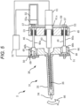
- a tip end of the injection nozzle 34 touches a concave surface of the sprue 14a and then is guided by the concave surface shifts in a lateral direction. That is, as shown in FIG. 4 , a lateral force 65 acts on the injection nozzle 34. Then, as shown in FIG. 5 , a moment 66 acts on the heating cylinder 35 and the front plate 44. A pressure due to a tensile force 69 is detected in the load cell 50 by the moment 66. That is, the pressure is detected as if the injection pressure was detected in the load cell 50. Accordingly, the controller 32 determines that misalignment has occurred.
- the reason why the occurrence of the misalignment can be detected in the load cell 50 in this way is that the occurrence of the moment 66 can be detected by the load cell 50. This is because the load cell 50 is disposed at a position separated from an extension line of the axis of the screw 36.
- the controller 32 can determine that the misalignment has occurred, and the controller 32 can also detect a direction of the misalignment based on whether the pressure is positive or negative. Further, the controller 32 can evaluate the magnitude of the misalignment based on the magnitude of the pressure.
- the injection device 3 configuring the injection molding machine 1 can also perform the nozzle touch method according to the present embodiment, and can detect misalignment between the injection nozzle 24 and a sprue (not shown) of the fixed mold 14.
- the screw driving device 22 of the injection device 3 will be described.
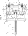
- the screw driving device 22 of the injection device 3 includes a front plate 71, a rear plate 72 provided parallel to and spaced from the front plate 71, and an intermediate plate 73 provided between the front plate 71 and the rear plate 72.
- the front plate 71 and the rear plate 72 are coupled by a plurality of guide rods 75, 75.
- the intermediate plate 73 is guided by the guide rods 75, 75 and is slidable.
- FIG. 8 shows the intermediate plate 73, two guide rods 75, 75 are provided in the present embodiment.
- the intermediate plate 73 and the rear plate 72 are coupled by four ball screw mechanisms 77, 77. Although only two ball screw mechanisms 77, 77 are shown in FIG. 7 , four ball screw mechanisms 77, 77, ... are provided as shown in FIG. 8 . As shown in FIG. 7 , through holes 79, 79, ... are formed in the rear plate 72, and ball screws 77a, 77a of the ball screw mechanisms 77, 77, ... are rotatably supported in a state where movement in the axial direction is restricted. Attachment holes 80, 80, ... are formed in the intermediate plate 73, and ball nuts 77b, 77b, ... of the ball screw mechanisms 77, 77, ... are inserted into the attachment holes 80, 80, ...
- two ball nuts 77b, 77b, ... two ball nuts 77b, 77b arranged diagonally are provided with load cells 82, 82, and the other two ball nuts 77b, 77b are provided with dummy load cells 83, 83, respectively.
- the load cells 82, 82 and the dummy load cells 83, 83 are fixed to the intermediate plate 73.
- the rear plate 72 is provided with two injection motors 85, 85, and ball screws 77a, 77a, ... are rotated by power transmission mechanisms 86, 86. Therefore, when the injection motors 85, 85 are driven, the intermediate plate 73 and the screw 20 are driven in the axial direction.
- a screw support portion 88 coupled to the screw 20 is rotatably provided on the intermediate plate 73.
- the intermediate plate 73 is provided with two plasticizing motors 89, 89 and the screw 20 is rotated by a power transmission mechanism 90 via the screw support portion 88.
- the injection nozzle 24 is indicated by a dotted line in FIG. 8 , there is a possibility that the injection nozzle 24 is misaligned in upper-lower and left-right directions.
- the load cells 82, 82 are provided corresponding to the two ball screw mechanisms 77, 77 arranged diagonally among the four ball screw mechanisms 77, 77, ..., so that the misalignment in the upper-lower direction and the misalignment in the left-right direction can be detected.
- a screw driving device may include a front plate that supports a heating cylinder at an end portion and an intermediate plate that rotatably supports a screw, and a load cell may be provided on the intermediate plate.
- FIG. 9 shows a subunit injection device 5' according to a second embodiment.
- a screw driving device 38' is modified, and ball nuts 46b, 46b of ball screw mechanisms 46, 46 are provided on an intermediate plate 45'.
- the load cell 50 is provided on the intermediate plate 45'.
- a moment acts on the heating cylinder 35 and a front plate 44'.
- a tensile force acts on one ball screw mechanism 46 and a pressing force acts on the other ball screw mechanism 46, and either positive or negative pressure is detected in the load cell 50. That is, misalignment can be detected.
- the load cell 50 is provided in one of the two ball screw mechanisms 46, 46 and the dummy load cell 51 is provided in the other.
- the load cell 50 may be provided in both of the two ball screw mechanisms 46, 46. That is, two load cells 50, 50 may be provided in the front plate 44 or the intermediate plate 45. In this way, misalignment can be detected more accurately.
- the injection device 3 according to the present embodiment has been described as including four ball screw mechanisms 77, 77, ..., of which only two ball screw mechanisms 77, 77 are provided with the load cells 82, 82.
- the other two ball screw mechanisms 77, 77 may also be provided with the load cells 82, 82 instead of the dummy load cells 83, 83.
- the load cells are preferably provided at two or more different positions in the screw driving device.
- a method is also preferable in which the load cells are provided at two or more different positions in the screw driving device, and the pressure of the load cells at the two or more positions is monitored to detect the misalignment between the injection nozzle and the sprue.
- an injection device that can easily detect the presence or absence of misalignment between an injection nozzle and a sprue of a mold, an injection molding machine, and a nozzle touch method.
Landscapes
- Engineering & Computer Science (AREA)
- Manufacturing & Machinery (AREA)
- Mechanical Engineering (AREA)
- Injection Moulding Of Plastics Or The Like (AREA)
Applications Claiming Priority (2)
| Application Number | Priority Date | Filing Date | Title |
|---|---|---|---|
| JP2021183864A JP7550132B2 (ja) | 2021-11-11 | 2021-11-11 | 射出装置、射出成形機、およびノズルタッチ方法 |
| PCT/JP2022/041977 WO2023085377A1 (fr) | 2021-11-11 | 2022-11-10 | Dispositif d'injection, machine de moulage par injection et méthode de miseen contact de buse |
Publications (2)
| Publication Number | Publication Date |
|---|---|
| EP4431261A1 true EP4431261A1 (fr) | 2024-09-18 |
| EP4431261A4 EP4431261A4 (fr) | 2025-02-12 |
Family
ID=86335892
Family Applications (1)
| Application Number | Title | Priority Date | Filing Date |
|---|---|---|---|
| EP22892875.0A Pending EP4431261A4 (fr) | 2021-11-11 | 2022-11-10 | Dispositif d'injection, machine de moulage par injection et méthode de miseen contact de buse |
Country Status (5)
| Country | Link |
|---|---|
| US (1) | US20250010532A1 (fr) |
| EP (1) | EP4431261A4 (fr) |
| JP (1) | JP7550132B2 (fr) |
| CN (1) | CN118201752A (fr) |
| WO (1) | WO2023085377A1 (fr) |
Families Citing this family (3)
| Publication number | Priority date | Publication date | Assignee | Title |
|---|---|---|---|---|
| JP7653169B2 (ja) * | 2023-04-25 | 2025-03-28 | 株式会社ニューギン | 遊技機 |
| CN117047970B (zh) * | 2023-08-14 | 2024-02-02 | 广东科腾精密机械有限公司 | 一种液态硅胶生产用独立卧式副射台及其使用方法 |
| JP2026009495A (ja) | 2024-07-08 | 2026-01-21 | 株式会社日本製鋼所 | 射出シリンダのスクリュの駆動機構とこれを備えた射出装置及び射出成形機、並びに駆動機構の製造方法 |
Family Cites Families (12)
| Publication number | Priority date | Publication date | Assignee | Title |
|---|---|---|---|---|
| JPH07106580B2 (ja) * | 1988-08-05 | 1995-11-15 | ファナック株式会社 | ノズルタッチ装置 |
| JPH02214631A (ja) * | 1989-02-15 | 1990-08-27 | Sumitomo Heavy Ind Ltd | 射出成形機のノズルタッチ装置 |
| JP4068493B2 (ja) | 2003-04-04 | 2008-03-26 | 住友重機械工業株式会社 | 射出成形機の監視装置及び監視方法 |
| JP4699383B2 (ja) | 2004-11-17 | 2011-06-08 | 住友重機械工業株式会社 | 射出成形機、可塑化移動装置及びノズルタッチ方法 |
| JP4249151B2 (ja) * | 2005-04-28 | 2009-04-02 | 住友重機械工業株式会社 | 射出成形機 |
| JP5755627B2 (ja) * | 2012-11-05 | 2015-07-29 | 株式会社日本製鋼所 | 射出成形機のノズルタッチ方法およびタッチ装置 |
| JP6023000B2 (ja) * | 2013-05-20 | 2016-11-09 | ファナック株式会社 | ノズルタッチ機構を有する射出成形機および射出成形機のノズルセンター合致判定方法 |
| JP6385832B2 (ja) | 2015-01-23 | 2018-09-05 | 住友重機械工業株式会社 | 射出成形機 |
| JP6682246B2 (ja) * | 2015-11-27 | 2020-04-15 | 住友重機械工業株式会社 | 射出装置 |
| JP2018122507A (ja) | 2017-01-31 | 2018-08-09 | 住友重機械工業株式会社 | 射出成形機 |
| CN211121717U (zh) | 2019-10-23 | 2020-07-28 | 宁波创基机械有限公司 | 一种注塑机喷嘴接触力的测试装置 |
| JP7456283B2 (ja) | 2020-05-22 | 2024-03-27 | オムロン株式会社 | 部材の結合構造 |
-
2021
- 2021-11-11 JP JP2021183864A patent/JP7550132B2/ja active Active
-
2022
- 2022-11-10 US US18/705,583 patent/US20250010532A1/en active Pending
- 2022-11-10 EP EP22892875.0A patent/EP4431261A4/fr active Pending
- 2022-11-10 WO PCT/JP2022/041977 patent/WO2023085377A1/fr not_active Ceased
- 2022-11-10 CN CN202280073975.XA patent/CN118201752A/zh active Pending
Also Published As
| Publication number | Publication date |
|---|---|
| JP7550132B2 (ja) | 2024-09-12 |
| JP2023071233A (ja) | 2023-05-23 |
| EP4431261A4 (fr) | 2025-02-12 |
| US20250010532A1 (en) | 2025-01-09 |
| CN118201752A (zh) | 2024-06-14 |
| WO2023085377A1 (fr) | 2023-05-19 |
Similar Documents
| Publication | Publication Date | Title |
|---|---|---|
| US20250010532A1 (en) | Injection device, injection molding machine, and nozzle touch method | |
| JP6348161B2 (ja) | 射出成形機の制御装置及び管理システム | |
| US9138923B2 (en) | Vertical injection molding machine | |
| JP4066057B1 (ja) | 電動式竪型射出成形機 | |
| US9283705B2 (en) | Injection unit for an injection molding machine | |
| JP6427369B2 (ja) | 動力伝達手段の異常検出装置、成形装置及び動力伝達手段の異常検出方法 | |
| JP2011005796A (ja) | トグル式型締装置におけるトグル機構の劣化診断方法および装置 | |
| JP2011121310A (ja) | 射出成形機 | |
| KR101428937B1 (ko) | 수직형 사출성형기 | |
| EP1741538A1 (fr) | Unité d'injection pour une machine de moulage par injection | |
| US20030219509A1 (en) | Injection molding machine | |
| TWI626144B (zh) | 射出裝置 | |
| EP3904039B1 (fr) | Injecteur | |
| JP2014124793A (ja) | 金型保護装置、金型保護方法及び型締装置 | |
| JP2003117936A (ja) | 竪型射出成形機のロータリテーブル装置 | |
| JP3740622B2 (ja) | 複数台の型締装置を備えた旋回式射出成形機の位置決め装置 | |
| US12090692B2 (en) | Injection molding apparatus with a mold conveyor, and method of controlling the mold conveyor and the injection molding apparatus | |
| EP3147097B1 (fr) | Machine de moulage à injection | |
| JP2008200953A (ja) | 電動式竪型射出成形機 | |
| JPH10109325A (ja) | 竪型射出装置 | |
| US20240157618A1 (en) | Control method for injection molding machine and injection molding machine | |
| US12491672B2 (en) | Screw adjustment method in thermosetting resin injection molding machine | |
| JP7710346B2 (ja) | 射出成形機 | |
| JP4270327B1 (ja) | 射出成形機の型締装置 | |
| KR100516438B1 (ko) | 수지봉지장치 |
Legal Events
| Date | Code | Title | Description |
|---|---|---|---|
| STAA | Information on the status of an ep patent application or granted ep patent |
Free format text: STATUS: THE INTERNATIONAL PUBLICATION HAS BEEN MADE |
|
| PUAI | Public reference made under article 153(3) epc to a published international application that has entered the european phase |
Free format text: ORIGINAL CODE: 0009012 |
|
| STAA | Information on the status of an ep patent application or granted ep patent |
Free format text: STATUS: REQUEST FOR EXAMINATION WAS MADE |
|
| 17P | Request for examination filed |
Effective date: 20240510 |
|
| AK | Designated contracting states |
Kind code of ref document: A1 Designated state(s): AL AT BE BG CH CY CZ DE DK EE ES FI FR GB GR HR HU IE IS IT LI LT LU LV MC ME MK MT NL NO PL PT RO RS SE SI SK SM TR |
|
| A4 | Supplementary search report drawn up and despatched |
Effective date: 20250115 |
|
| RIC1 | Information provided on ipc code assigned before grant |
Ipc: B29C 45/76 20060101ALI20250109BHEP Ipc: B29C 45/50 20060101ALI20250109BHEP Ipc: B29C 45/84 20060101ALI20250109BHEP Ipc: B29C 45/17 20060101ALI20250109BHEP Ipc: B29C 45/20 20060101AFI20250109BHEP |
|
| DAV | Request for validation of the european patent (deleted) | ||
| DAX | Request for extension of the european patent (deleted) |