EP4432018A1 - Mouvement horloger comprenant un mécanisme de remontage automatique - Google Patents
Mouvement horloger comprenant un mécanisme de remontage automatique Download PDFInfo
- Publication number
- EP4432018A1 EP4432018A1 EP23162695.3A EP23162695A EP4432018A1 EP 4432018 A1 EP4432018 A1 EP 4432018A1 EP 23162695 A EP23162695 A EP 23162695A EP 4432018 A1 EP4432018 A1 EP 4432018A1
- Authority
- EP
- European Patent Office
- Prior art keywords
- winding
- movement
- mass
- rotating arms
- barrel
- Prior art date
- Legal status (The legal status is an assumption and is not a legal conclusion. Google has not performed a legal analysis and makes no representation as to the accuracy of the status listed.)
- Withdrawn
Links
Images


Classifications
-
- G—PHYSICS
- G04—HOROLOGY
- G04B—MECHANICALLY-DRIVEN CLOCKS OR WATCHES; MECHANICAL PARTS OF CLOCKS OR WATCHES IN GENERAL; TIME PIECES USING THE POSITION OF THE SUN, MOON OR STARS
- G04B5/00—Automatic winding up
- G04B5/02—Automatic winding up by self-winding caused by the movement of the watch
- G04B5/10—Automatic winding up by self-winding caused by the movement of the watch by oscillating weights the movement of which is not limited
- G04B5/14—Automatic winding up by self-winding caused by the movement of the watch by oscillating weights the movement of which is not limited acting in both directions
-
- G—PHYSICS
- G04—HOROLOGY
- G04B—MECHANICALLY-DRIVEN CLOCKS OR WATCHES; MECHANICAL PARTS OF CLOCKS OR WATCHES IN GENERAL; TIME PIECES USING THE POSITION OF THE SUN, MOON OR STARS
- G04B45/00—Time pieces of which the indicating means or cases provoke special effects, e.g. aesthetic effects
- G04B45/02—Time pieces of which the clockwork is visible partly or wholly
-
- G—PHYSICS
- G04—HOROLOGY
- G04B—MECHANICALLY-DRIVEN CLOCKS OR WATCHES; MECHANICAL PARTS OF CLOCKS OR WATCHES IN GENERAL; TIME PIECES USING THE POSITION OF THE SUN, MOON OR STARS
- G04B5/00—Automatic winding up
- G04B5/02—Automatic winding up by self-winding caused by the movement of the watch
- G04B5/18—Supports, suspensions or guide arrangements, for oscillating weights
- G04B5/184—Guide arrangement of the moving weight in a circular course
Definitions
- the present invention relates to the field of watchmaking and more particularly to a watch movement comprising an automatic winding mechanism.
- This mechanism comprises a winding mass arranged to perform a circular translational movement.
- Automatic winding mechanisms most often use a semi-circular oscillating weight mounted pivotally in the center of the watch movement along an axis perpendicular to the general plane of the latter.
- a disadvantage of this type of oscillating weight lies in its location on the back of the watch case, hiding, at least in part, the watch movement. Such an arrangement is not always desirable, especially when the back is a sapphire crystal in order to make an original visual aspect of the movement visible.
- CH706350 proposes a watch movement comprising a frame, various organs, including a barrel and gears mounted on the frame as well as an automatic winding mechanism for reloading the barrel.
- This winding mechanism comprises a winding mass and transmission means arranged to transmit the movement of the winding mass to the barrel to wind it.
- the winding mass is mounted articulated on at least two arms pivotally mounted on the frame.
- the winding mass is further arranged to perform a circular translation movement which can be complete around the frame in a plane perpendicular to the general plane of the watch movement.
- CH157093 And CH168493 disclose another example of a self-winding watch movement, comprising an unconventional oscillating weight.
- the winding mechanism comprises a frame comprising in particular a barrel and a winding weight. The latter is connected to the frame by several arms whose axis of rotation is parallel to the general plane of the watch movement. The distance between the winding weight and the frame varies according to the position of the weight. It is therefore necessary, like CH706350 , to provide sufficient volume in the watch case for the movement of the winding mass.
- the plane in which the winding mass oscillates according to the above mechanisms is not optimal in relation to the most frequent general movements of a wearer's arm, which are swinging movements of the arm along the body. This has a significant impact on the winding efficiency of the barrel.
- An aim of the present invention is therefore to propose a watch movement comprising a winding mechanism automatic which does not hide the movement while solving, at least in part, the aforementioned problems of the prior art.
- a watch movement comprising in particular a frame, gears, a barrel and an automatic winding mechanism for winding the barrel.
- the winding mechanism comprises a winding mass mounted articulated on the frame by means of rotating arms so that the winding mass can perform a circular translational movement.
- the winding mechanism further comprises transmission means arranged to transmit the movement of the winding mass to the barrel.
- the winding mass is connected to the rotating arms so as to constrain the circular translational movement of the mass in a plane parallel to the general plane of the watch movement.
- the rotating arms are further free to pivot through 360°.
- the watch movement further comprises an armature secured to the winding mass or forming a single piece with the mass.
- the rotating arms are pivotally connected to the armature.
- the rotating arms are further arranged to pivot in a plane located between the armature and the frame.
- the armature comprises at least a first and a second fixing part on which the rotating arms are connected, and at least a first and a second support each supporting a weight of the winding mass.
- the fixing parts and the supports are each arranged alternately on the armature around a central part of the watch movement.
- the weights are arranged on only one face of the frame.
- the first and second fixing parts are each connected to the frame by two rotating arms.
- the weights each comprise an external face intended to be mounted opposite a portion of the case middle of a watch case when the watch movement is mounted in the case, and an internal face opposite the external face.
- the internal face of at least one of the weights comprises a clearance to be able to partially envelop at least one organ of the watch movement, in particular a gear train, when a circular translation movement is imparted to the winding weight.
- At least one of the weights comprises a cutout for the passage of a control stem such as a time-setting stem.
- the winding mass is articulated on the frame by means of three or four rotating arms.
- the winding mass comprises three weights which are each arranged between two rotating arms.
- the transmission means comprise a gear train engaged with the barrel ratchet. At least one of the rotating arms is secured to a transmission shaft comprising a transmission wheel engaged with the gear train and arranged to be driven in rotation by the rotation of said at least one rotating arm.
- the transmission means comprise a pull lever and a push lever.
- the pull and push levers comprise at a first end a pawl configured to respectively pull and push a tooth of the barrel ratchet or of a wheel engaged with the barrel ratchet, alternately so that the barrel ratchet is actuated in rotation in a single direction.
- the pull and push levers each comprise a second end secured to one of the rotating arms.
- At least one elastic member is integral with the winding mass. This elastic member is arranged to act on an actuable part of the traction lever and the push lever in order to constrain their respective pawl against the barrel ratchet or the wheel engaged with the ratchet.
- Another aspect of the invention relates to a timepiece comprising the watch movement according to one of the above-mentioned embodiments.
- the watch movement 10 comprises a frame 12, 12a, 12b, various organs, including a barrel 60, gears 11 and an automatic winding mechanism for winding the barrel 60.
- the winding mechanism comprises a winding mass 14 connected to the frame 12 by several rotating arms, for example three or four rotating arms 30a, 30b, 30c, 30d so that a circular translation movement can be imparted to the winding mass 14 in a single plane whose orientation corresponds to that of the general plane of the watch movement.
- This makes it possible to reduce the thickness of the watch movement compared to the existing circular translation automatic winding mechanisms mentioned above.
- This also makes it possible to optimize the winding of the barrel, in particular because this plane corresponds to that of the natural swing of the arm of a wearer of a wristwatch, when the latter moves while walking.
- the winding mass 14 comprises an armature 16 as well as two separate masses 18a, 18b, hereinafter referred to as weights, fixed to the armature 16.
- the two weights 18a, 18b and the armature 16 may be in one piece according to one variant.
- the armature 16 has a substantially rectangular or square shape arranged around a central part of the watch movement 10 in order to make this central part visible through a transparent back of a watch case containing the movement.
- the transparent back may in particular be a sapphire crystal.
- the armature 16 comprises two fixing parts 16a, 16b arranged facing each other and on either side of the central part of the watch movement as well as a first and a second support 16c, 16d on which the two weights 18a, 18b of the winding mass 14.
- the two supports 16c, 16d preferably constitute, for the weights, support surfaces which extend opposite one another substantially perpendicular to the two fixing parts 16a, 16b.
- These each comprise two counterbores 17a, 17b at the orifice of two screw holes.
- Screws 22 are mounted in the screw holes with their end screwed into a hole in each rotating arm and their screw head embedded in the counterbore 17 as illustrated in figure 6 .
- a bearing 23 is mounted between the screw body and the screw hole to ensure rotation of the armature 16 relative to the screws 22.
- the winding mass may comprise three weights which are each arranged between two rotating arms which connect the armature to the frame of the watch movement.
- the armature may comprise for this purpose three fixing parts which are each connected to the frame by a rotating arm. These three fixing parts are arranged around a central part of the watch movement alternately with three supports on which the three weights are fixed. These can form a single piece with the three supports of the armature according to a variant.
- the shape of the armature is substantially rectangular according to the illustrated embodiment, it could have a substantially annular shape according to a variant.
- three arms 30b, 30c, 30d of the four rotating arms can be mounted on simple pivots 32 while the fourth arm 30a is mounted on a transmission shaft according to the detailed description below.
- the four rotating arms are mounted on two bridges 12a, 12b ( figure 1 ) located on two opposite sides of the watch movement 10 so that these rotating arms are located close to the four corners of the watch movement as can be seen in the figure 3 .
- each pivot 32 extends perpendicular to the general plane of the watch movement so that the four rotating arms can pivot in a plane whose orientation is identical to the general plane of the watch movement in order to constrain the circular translation movements in this plane.
- Each rotating arm 30a, 30b, 30c, 30d is further arranged to be free to rotate over 360°, in particular in a plane located between the armature and the bridges 12a, 12b of the frame, in order to be able to impart to the winding mass 14 the sequence of the circular translation movement illustrated by the Figures 9a to 9d .
- the height of the visible face of the two bridges 12a, 12b relative to the frame 12 corresponds substantially to the thickness of the two weights 18a, 18b of the winding mass 14 in order to form two hollow volumes arranged on either side of the central part of the movement.
- the two weights 18a, 18a can thus move inside these two volumes according to the circular translational movement of the winding mass 14.
- the two weights 18a, 18b ( Figures 4a and 4b ) each comprise an external face 19a intended to be mounted opposite a portion of the case middle of a watch case when the watch movement is mounted in the case, and an internal face 19b opposite the external face.
- the internal face 19b of at least one of the two weights 18a, 18b comprises a clearance 20 so that the winding mass 14 can partially and temporarily envelop an organ of the watch movement without coming into contact with the latter, in particular one or more gears 11, when a circular translation movement is imparted to the winding mass 14.
- At least one of the weights 18a, 18b comprises a cutout 21 in order to form with the frame 12 an opening for the passage of a control stem, in particular a winding or time-setting stem 80.
- the automatic winding mechanism further comprises transmission means for winding the barrel 60 according to the circular translational movement of the winding mass 14.
- a gear train is engaged with the ratchet 70 of the barrel 60 and comprises a transmission wheel 42 secured to a transmission shaft 41 mounted on two bearings 41a, 41b and on which the fourth rotary arm 30a is fixed.
- the transmission wheel 42 meshes with a conventional inverter 43 which comprises a first and a second clutch mobile 44, 45.
- the transmission wheel 42 is engaged with a clutch wheel 44a of the first clutch mobile 44.
- a clutch wheel 45a of the second clutch mobile 45 meshes with the clutch wheel 44a of the first mobile while the pinions 44b (only the pinion of the first clutch mobile is visible on the figure 6 ) of the two clutch mobiles are engaged with a first mobile 46 of a reduction gear.
- the pinion of the first mobile 46 meshes with the wheel 47a of a second mobile 47 whose pinion 47b is engaged with the barrel ratchet 70 to actuate the rotation of the barrel shaft.
- the operation of this type of reverser is well known to those skilled in the art and will therefore not be described.
- first and second clutch mobiles can be of different types, for example ratchet, ball or spring.
- a wolf-toothed wheel 72 secured to the barrel shaft cooperates with a ratchet 74 located at the end of a leaf spring 76.
- the means of transmission to wind the barrel as desired circular translation movement of the winding mass 14, comprise a pull lever 50, and a push lever 52. These two levers comprise at a first end a pawl 50a, 52a configured to respectively pull and push a tooth of the barrel ratchet 70 or a tooth of an intermediate wheel engaged with the ratchet according to a variant not illustrated.
- Two of the four rotating arms are connected to an actuable portion 50b, 52b located at a second end of the pull lever 50 and the push lever 52 by means of an axle 56 mounted through an opening 51, 53.
- the latter can thus be actuated in rotation in a single direction according to the circular translational movement of the winding mass 14.
- the armature 16 of the winding mass 14 comprises on a lower face at least one elastic member 54 which in particular is for example in the form of two spring blades 54a, 54b arranged to act on the actuable part 50b, 52b of the traction lever 50 and of the thrust lever 52 to constrain their respective pawl 50a, 52a against the barrel ratchet 70.
Landscapes
- Physics & Mathematics (AREA)
- General Physics & Mathematics (AREA)
- Electromechanical Clocks (AREA)
Abstract
La présente invention concerne un mouvement horloger (10) comportant notamment un bâti (12, 12a, 12b), des rouages (11), un barillet (60) et un mécanisme de remontage automatique pour remonter le barillet (60). Le mécanisme de remontage comporte une masse de remontage (14) montée articulée sur le bâti (12a, 12b) par l'intermédiaire de bras rotatifs (30a, 30b, 30c, 30d) pour que la masse de remontage (14) puisse effectuer un mouvement de translation circulaire. Le mécanisme de remontage comporte en outre des moyens de transmission agencés pour transmettre le mouvement de la masse de remontage (14) au barillet (60). La masse de remontage (14) est reliée aux bras rotatifs (30a, 30b, 30c, 30d) de sorte à contraindre le mouvement de translation circulaire de ladite masse (14) dans un plan parallèle au plan général du mouvement horloger. Les bras rotatifs (30a, 30b, 30c, 30d) sont en outre libres de pivoter sur 360°.
Description
- La présente invention se rapporte au domaine de l'horlogerie et plus particulièrement à un mouvement horloger comprenant un mécanisme de remontage automatique. Ce mécanisme comporte une masse de remontage agencée pour effectuer un mouvement de translation circulaire.
- Les mécanismes de remontage automatiques utilisent le plus souvent une masse oscillante de forme semi-circulaire et montée pivotante au centre du mouvement horloger selon un axe perpendiculaire au plan général de celui-ci. Un inconvénient de ce type de masse oscillante réside dans son emplacement côté fond de la boite de montre cachant, au moins en partie, le mouvement horloger. Un tel agencement n'est en effet pas toujours souhaitable notamment lorsque le fond est une glace saphir afin de rendre visible un aspect visuel original du mouvement.
- Afin de résoudre cette problématique,
CH706350 - Il convient par conséquent de prévoir un volume significatif dans la boite de montre pour permettre les mouvements de la masse de remontage dans le plan perpendiculaire susvisé. Cela a un impact sur l'épaisseur de la boite de montre qui doit être suffisante pour que l'amplitude des mouvements de la masse permette un remontage efficace du barillet.
-
CH157093 CH168493 CH706350 - Par ailleurs, le plan dans lequel oscille la masse de remontage selon les mécanismes susvisés n'est pas optimal par rapport aux mouvements généraux les plus fréquents du bras d'un porteur, qui sont des mouvements de balancement du bras le long du corps. Cela a un impact non négligeable sur le rendement de remontage du barillet.
- Un but de la présente invention est par conséquent de proposer un mouvement horloger comprenant un mécanisme de remontage automatique qui ne cache pas le mouvement tout en résolvant, au moins en partie, les problèmes précités de l'art antérieur.
- Ce but est atteint par un mouvement horloger comportant notamment un bâti, des rouages, un barillet et un mécanisme de remontage automatique pour remonter le barillet. Le mécanisme de remontage comporte une masse de remontage montée articulée sur le bâti par l'intermédiaire de bras rotatifs pour que la masse de remontage puisse effectuer un mouvement de translation circulaire. Le mécanisme de remontage comporte en outre des moyens de transmission agencés pour transmettre le mouvement de la masse de remontage au barillet. La masse de remontage est reliée aux bras rotatifs de sorte à contraindre le mouvement de translation circulaire de la masse dans un plan parallèle au plan général du mouvement horloger. Les bras rotatifs sont en outre libres de pivoter sur 360°.
- Selon une forme de réalisation, le mouvement horloger comporte en outre une armature solidaire de la masse de remontage ou formant un seul tenant avec la masse. Les bras rotatifs sont connectés de manière pivotante à l'armature. Les bras rotatifs sont en outre agencés pour pivoter dans un plan situé entre l'armature et le bâti.
- Selon une forme de réalisation, l'armature comprend au moins une première et une seconde partie de fixation sur lesquelles sont connectés les bras rotatifs, et au moins un premier et un second support supportant chacun une masselotte de la masse de remontage. Les parties de fixation et les supports sont chacun arrangés en alternance sur l'armature autour d'une partie centrale du mouvement horloger.
- Selon une forme de réalisation, les masselottes sont agencées sur une seule face de l'armature.
- Selon une forme de réalisation, les première et seconde parties de fixation sont chacune connectées au bâti par deux bras rotatifs.
- Selon une forme de réalisation, les masselottes comportent chacune une face externe destinée à être montée en regard d'une portion de la carrure d'une boite de montre lorsque le mouvement horloger est monté dans la boite, et une face interne opposée à la face externe. La face interne d'au moins une des masselottes comporte un dégagement pour pouvoir envelopper partiellement au moins un organe du mouvement horloger, notamment un rouage, lorsqu'un mouvement de translation circulaire est imprimé à la masse de remontage.
- Selon une forme de réalisation, au moins une des masselottes comporte une découpe pour le passage d'une tige de commande telle qu'une tige de mise à l'heure.
- Selon une forme de réalisation, la masse de remontage est articulée sur le bâti par l'intermédiaire de trois ou quatre bras rotatifs.
- Selon une forme de réalisation, la masse de remontage comporte trois masselottes qui sont chacune agencées entre deux bras rotatifs.
- Selon une forme de réalisation, les moyens de transmission comportent un train d'engrenage en prise avec le rochet de barillet. Au moins un des bras rotatifs est solidaire d'un arbre de transmission comprenant une roue de transmission en prise avec le train d'engrenage et agencée pour être entraînée en rotation par la rotation dudit au moins un bras rotatif.
- Selon une forme de réalisation, les moyens de transmission comportent un levier de traction et un levier de poussée. Les leviers de traction et de poussée comportent à une première extrémité un cliquet configuré pour respectivement tirer et pousser une dent du rochet de barillet ou d'une roue en prise avec le rochet de barillet, de manière alternative afin que le rochet de barillet soit actionné en rotation dans un sens unique. Les leviers de traction et de poussée comportent chacun une seconde extrémité solidaire d'un des bras rotatifs.
- Selon une forme de réalisation, au moins un organe élastique est solidaire de la masse de remontage. Cet organe élastique est agencé pour agir sur une partie actionnable du levier de traction et du levier de poussée afin de contraindre leur cliquet respectif contre le rochet de barillet ou la roue en prise avec le rochet.
- Un autre aspect de l'invention porte sur une pièce d'horlogerie comportant le mouvement horloger selon l'une des formes de réalisation susvisées.
- Des exemples de mise en oeuvre de l'invention sont indiqués dans la description illustrée par les figures annexées dans lesquelles :
- la
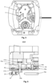
figure 1 illustre une vue en perspective d'un mouvement horloger comprenant une masse de remontage selon une forme de réalisation de l'invention ; - la
figure 2 illustre une vue en perspective du mouvement horloger de lafigure 1 selon une autre orientation, - la
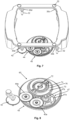
figure 3 illustre une vue similaire à lafigure 2 sans la masse de remontage ; - les
figures 4a et 4b illustrent une vue en perspective de la masse de remontage de lafigure 1 selon une première et une seconde orientation ; - la
figure 5 illustre une vue de dessus du mouvement horloger de lafigure 1 du côté de la masse de remontage ; - la
figure 6 illustre une vue en coupe du mouvement horloger de lafigure 5 selon A-A; - la
figure 7 illustre une vue en perspective de la chaîne cinématique reliant la masse de remontage au barillet du mouvement horloger; - la
figure 8 illustre une vue agrandie de la chaîne cinématique de lafigure 7 ; - les
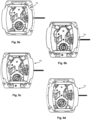
figures 9a à 9d illustrent une séquence de mouvement de translation circulaire de la masse de remontage ; - la
figure 10a illustre une vue simplifiée d'un mouvement horloger comprenant des moyens de transmission du mouvement de la masse au barillet selon une autre forme de réalisation, et - la
figure 10b illustre une vue similaire à lafigure 10a sans la masse de remontage. - En référence aux
figures 1 à 8 , le mouvement horloger 10 comporte un bâti 12, 12a, 12b, différents organes, dont un barillet 60, des rouages 11 et un mécanisme de remontage automatique pour remonter le barillet 60. Le mécanisme de remontage comporte une masse de remontage 14 reliée au bâti 12 par plusieurs bras rotatifs, par exemple trois ou quatre bras rotatifs 30a, 30b, 30c, 30d afin qu'un mouvement de translation circulaire puisse être imprimé à la masse de remontage 14 dans un plan unique dont l'orientation correspond à celle du plan général du mouvement horloger. Cela permet de réduire l'épaisseur du mouvement horloger par rapport aux mécanismes de remontage automatiques à translation circulaire existants mentionnés précédemment. Cela permet également d'optimiser le remontage du barillet, notamment du fait que ce plan corresponde à celui du balancement naturel du bras d'un porteur d'une montre-bracelet, lorsque ce dernier se déplace en marchant. - A cet effet, au vu des
figures 4a, 4b , la masse de remontage 14 comporte une armature 16 ainsi que deux masses distinctes 18a, 18b, dénommées ci-après masselottes, fixées à l'armature 16. Les deux masselottes 18a, 18b et l'armature 16 peuvent être d'un seul tenant selon une variante. L'armature 16 possède une forme sensiblement rectangulaire ou carrée agencée autour d'une partie centrale du mouvement horloger 10 afin de rendre visible cette partie centrale à travers un fond transparent d'une boite de montre renfermant le mouvement. Le fond transparent peut être en particulier une glace saphir. - Plus particulièrement, l'armature 16 comporte deux parties de fixation 16a, 16b agencées en regard l'une de l'autre et de part et d'autre de la partie centrale du mouvement horloger ainsi qu'un premier et un second support 16c, 16d sur lesquels sont fixées les deux masselottes 18a, 18b de la masse de remontage 14. Les deux supports 16c, 16d constituent de préférence, pour les masselottes, des surfaces de support qui s'étendent en regard l'une de l'autre sensiblement perpendiculairement aux deux parties de fixation 16a, 16b. Celles-ci comportent chacune deux lamages 17a, 17b à l'orifice de deux trous de vis. Des vis 22 sont montées dans les trous de vis avec leur extrémité vissée dans un trou de chaque bras rotatif et leur tête de vis noyée dans le lamage 17 comme illustré à la
figure 6 . Un palier 23 est monté entre le corps de vis et le trou de vis pour garantir la rotation de l'armature 16 par rapport aux vis 22. - Selon une forme de réalisation non-illustrée, la masse de remontage peut comporter trois masselottes qui sont chacune agencées entre deux bras rotatifs qui connectent l'armature au bâti du mouvement horloger. L'armature peut comporter à cet effet trois parties de fixation qui sont chacune connectées au bâti par un bras rotatif. Ces trois parties de fixation sont agencées autour d'une partie centrale du mouvement horloger en alternance avec trois supports sur lesquelles sont fixées les trois masselottes. Celles-ci peuvent former un seul tenant avec les trois supports de l'armature selon une variante. Bien que la forme de l'armature est sensiblement rectangulaire selon la forme de réalisation illustrée, elle pourrait avoir une forme sensiblement annulaire selon une variante.
- Selon l'exemple de la
figure 7 , trois bras 30b, 30c, 30d des quatre bras rotatifs peuvent être montés sur de simple pivots 32 alors que le quatrième bras 30a est monté sur un arbre de transmission selon la description détaillée ci-après. Les quatre bras rotatifs sont montés sur deux ponts 12a, 12b (figure 1 ) situés sur deux côtés opposés du mouvement horloger 10 de sorte à ce que ces bras rotatifs se situent proche des quatre coins du mouvement horloger comme on peut le voir sur lafigure 3 . - L'axe de chaque pivot 32 s'étend perpendiculairement au plan général du mouvement horloger afin que les quatre bras rotatifs puissent pivoter dans un plan dont l'orientation est identique au plan général de mouvement horloger afin de contraindre les mouvements de translation circulaire dans ce plan. Chaque bras rotatif 30a, 30b, 30c, 30d est en outre agencé pour être libre en rotation sur 360°, en particulier dans un plan situé entre l'armature et les ponts 12a, 12b du bâti, afin de pouvoir impartir à la masse de remontage 14 la séquence du mouvement de translation circulaire illustrée par les
figures 9a à 9d . - En référence à la
figure 1 , la hauteur de la face visible des deux ponts 12a, 12b par rapport au bâti 12 correspond sensiblement à l'épaisseur des deux masselottes 18a, 18b de la masse de remontage 14 afin de former deux volumes évidés agencés de part et d'autre de la partie centrale du mouvement. Les deux masselottes 18a, 18a peuvent ainsi se déplacer à l'intérieur de ces deux volumes au gré du mouvement de translation circulaire de la masse de remontage 14. - Les deux masselottes 18a, 18b (
figures 4a et 4b ) comportent chacune une face externe 19a destinée à être montée en regard d'une portion de la carrure d'une boite de montre lorsque le mouvement horloger est monté dans la boite, et une face interne 19b opposée à la face externe. La face interne 19b d'au moins une des deux masselottes 18a, 18b comporte un dégagement 20 afin que la masse de remontage 14 puisse partiellement et temporairement envelopper un organe du mouvement horloger sans venir en contact de celui-ci, notamment un ou plusieurs rouages 11, lorsqu'un mouvement de translation circulaire est imprimé à la masse de remontage 14. - De préférence, au moins l'une des masselottes 18a, 18b comporte une découpe 21 afin de former avec le bâti 12 une ouverture pour le passage d'une tige de commande, en particulier une tige de remontoir ou de mise à l'heure 80.
- En référence aux
figures 6 à 8 , le mécanisme de remontage automatique comporte en outre des moyens de transmission pour remonter le barillet 60 au gré du mouvement de translation circulaire de la masse de remontage 14. A cet effet, un train d'engrenage est en prise avec le rochet 70 du barillet 60 et comporte une roue de transmission 42 solidaire d'un arbre de transmission 41 monté sur deux paliers 41a, 41b et sur lequel est fixé le quatrième bras rotatif 30a. La roue de transmission 42 engrène avec un inverseur conventionnel 43 qui comporte un premier et un second mobile d'embrayage 44, 45. - Plus particulièrement, la roue de transmission 42 est en prise avec une roue d'embrayage 44a du premier mobile d'embrayage 44. Une roue d'embrayage 45a du second mobile d'embrayage 45 engrène avec la roue d'embrayage 44a du premier mobile alors que les pignons 44b (seul le pignon du premier mobile d'embrayage est visible sur la
figure 6 ) des deux mobiles d'embrayage sont en prise avec un premier mobile 46 d'un engrenage réducteur. Le pignon du premier mobile 46 engrène avec la roue 47a d'un second mobile 47 dont le pignon 47b est en prise avec le rochet 70 de barillet pour actionner la rotation de l'arbre de barillet. Le fonctionnement de ce type d'inverseur est bien connu de l'homme du métier et ne sera par conséquent pas d'écrit. On relèvera toutefois que les premier et second mobiles d'embrayage peuvent être de différents types, par exemple à cliquet, à bille ou à ressort. Une roue à dents de loup 72 solidaire de l'arbre de barillet coopère avec un cliquet 74 situé à l'extrémité d'une lame-ressort 76. - Selon une autre forme de réalisation illustrée par les
figures 10a et 10b , les moyens de transmission pour remonter le barillet au gré du mouvement de translation circulaire de la masse de remontage 14, comportent un levier de traction 50, et un levier de poussée 52. Ces deux leviers comportent à une première extrémité un cliquet 50a, 52a configuré pour respectivement tirer et pousser une dent du rochet 70 de barillet ou une dent d'une roue intermédiaire en prise avec le rochet selon une variante non-illustrée. - Deux des quatre bras rotatifs sont connectés à une partie actionnable 50b, 52b située à une seconde extrémité du levier de traction 50 et du levier de poussée 52 par l'intermédiaire d'un axe 56 monté au travers d'une ouverture 51, 53. Cela permet d'actionner le levier de traction 50 et le levier de poussée 52 afin que leur cliquet respectif 50a, 52a tire et pousse une dent du rochet de barillet 70. Ce dernier peut ainsi être actionné en rotation dans un sens unique au gré du mouvement de translation circulaire de la masse de remontage 14.
- L'armature 16 de la masse de remontage 14 comporte sur une face inférieure au moins un organe élastique 54 qui notamment se présente par exemple sous la forme de deux lames-ressort 54a, 54b agencées pour agir sur la partie actionnable 50b, 52b du levier de traction 50 et du levier de poussée 52 pour contraindre leur cliquet respectif 50a, 52a contre le rochet 70 de barillet.
- Le fonctionnent de ces moyens transmission selon cette seconde forme de réalisation s'apparente à un système de type Pellaton dont l'excentrique est remplacé par les deux bras rotatifs.

Claims (13)
- Mouvement horloger (10) comportant notamment un bâti (12, 12a, 12b), des rouages (11), un barillet (60) et un mécanisme de remontage automatique pour remonter le barillet (60), le mécanisme de remontage comportant une masse de remontage (14) montée articulée sur le bâti (12a, 12b) par l'intermédiaire de bras rotatifs (30a, 30b, 30c, 30d) pour que la masse de remontage (14) puisse effectuer un mouvement de translation circulaire, le mécanisme de remontage comportant en outre des moyens de transmission agencés pour transmettre le mouvement de la masse de remontage (14) au barillet (60), caractérisé en ce que la masse de remontage (14) est reliée audits bras rotatifs (30a, 30b, 30c, 30d) de sorte à contraindre le mouvement de translation circulaire de ladite masse (14) dans un plan parallèle au plan général du mouvement horloger et en ce que lesdits bras rotatifs (30a, 30b, 30c, 30d) sont libres de pivoter sur 360°.
- Mouvement horloger (10) selon la revendication 1, caractérisé en ce qu'il comporte en outre une armature (16) solidaire de la masse de remontage (14) ou formant un seul tenant avec ladite masse (14), et en ce que les bras rotatifs (30a, 30b, 30c, 30d) sont connectés de manière pivotante à l'armature (16), lesdits bras rotatifs étant agencés entre ladite armature (16) et le bâti (12a, 12b).
- Mouvement horloger selon la revendication précédente, caractérisé en ce que l'armature (16) comprend au moins une première et une seconde partie de fixation (16a, 16b) sur lesquelles sont connectés les bras rotatifs, et au moins un premier et un second support (16c, 16d) supportant chacun une masselotte (18a, 18b) de la masse de remontage (14), lesdites parties de fixation (16a, 16b) et lesdits supports (16c, 16d) étant chacun arrangés en alternance sur l'armature (16) autour d'une partie centrale du mouvement horloger.
- Mouvement horloger selon la revendication précédente, caractérisé en ce que les masselottes (18a, 18b) sont agencées sur une seule face de l'armature (16).
- Mouvement horloger selon la revendication 3 ou 4, caractérisé en ce que lesdites au moins première et seconde parties de fixation (16a, 16b) sont chacune connectées au bâti (12a, 12b) par deux bras desdits bras rotatifs.
- Mouvement horloger selon l'une des revendications 3 à 5, caractérisé en ce que les masselottes (18a, 18b) comportent chacune une face externe (19a) destinée à être montée en regard d'une portion de la carrure d'une boite de montre lorsque le mouvement horloger est monté dans ladite boite, et une face interne (19b) opposée à la face externe, la face interne (19b) d'au moins une des masselottes (18a, 18b) comportant un dégagement (20) pour pouvoir envelopper partiellement au moins un organe du mouvement horloger, notamment un rouage (11), lorsqu'un mouvement de translation circulaire est imprimé à la masse de remontage (14).
- Mouvement horloger selon l'une des revendications 3 à 6, caractérisé en ce qu'au moins l'une des masselottes (18a, 18b) comporte une découpe (21) pour le passage d'une tige de commande telle qu'une tige de mise à l'heure (80).
- Mouvement horloger selon l'une des revendications précédentes, caractérisé en ce que la masse de remontage (14) est articulée sur le bâti (12a, 12b) par l'intermédiaire de trois ou quatre bras rotatifs.
- Mouvement horloger selon l'une des revendications précédentes, caractérisé en ce que la masse de remontage comporte trois masselottes qui sont chacune agencées entre deux bras rotatifs.
- Mouvement horloger (10) selon l'une des revendications précédentes, caractérisé en ce que les moyens de transmission comportent un train d'engrenage en prise avec le rochet (70) de barillet, au moins un des bras rotatifs (30a, 30b, 30c, 30d) étant solidaire d'un arbre de transmission (41) comprenant une roue de transmission (42) en prise avec le train d'engrenage et agencée pour être entraînée en rotation par la rotation dudit au moins un bras rotatif.
- Mouvement horloger (10) selon l'une des revendications 1 à 9, caractérisé en ce que les moyens de transmission comportent un levier de traction (50), et un levier de poussée (52), les leviers de traction et de poussée (50, 52) comportant à une première extrémité un cliquet (50a, 52a) configuré pour respectivement tirer et pousser une dent du rochet (70) de barillet ou d'une roue en prise avec le rochet de barillet, de manière alternative afin que ledit rochet (70) soit actionné en rotation dans un sens unique, les leviers de traction et de poussée (50, 52) comportant chacun une seconde extrémité solidaire d'un desdits bras rotatifs (30a, 30b).
- Mouvement horloger (10) selon la revendication précédente, caractérisé en ce que le masse de remontage (14) comporte au moins un organe élastique (54) agissant sur une partie actionnable (50b, 52b) du levier de traction (50) et du levier de poussée (52) pour contraindre leur cliquet respectif (50a, 52a) contre le rochet de barillet (70) ou ladite roue.
- Pièce d'horlogerie comportant le mouvement horloger selon l'une des revendications précédentes.
Priority Applications (5)
| Application Number | Priority Date | Filing Date | Title |
|---|---|---|---|
| EP23162695.3A EP4432018A1 (fr) | 2023-03-17 | 2023-03-17 | Mouvement horloger comprenant un mécanisme de remontage automatique |
| JP2025546479A JP2026503863A (ja) | 2023-03-17 | 2024-03-14 | 自動巻き機構を備えた時計のムーブメント |
| EP24712142.9A EP4681026A1 (fr) | 2023-03-17 | 2024-03-14 | Mouvement horloger comprenant un mécanisme de remontage automatique |
| PCT/IB2024/052498 WO2024194761A1 (fr) | 2023-03-17 | 2024-03-14 | Mouvement horloger comprenant un mécanisme de remontage automatique |
| CN202480019054.4A CN120883151A (zh) | 2023-03-17 | 2024-03-14 | 包括自动上发条机构的钟表机芯 |
Applications Claiming Priority (1)
| Application Number | Priority Date | Filing Date | Title |
|---|---|---|---|
| EP23162695.3A EP4432018A1 (fr) | 2023-03-17 | 2023-03-17 | Mouvement horloger comprenant un mécanisme de remontage automatique |
Publications (1)
| Publication Number | Publication Date |
|---|---|
| EP4432018A1 true EP4432018A1 (fr) | 2024-09-18 |
Family
ID=85704665
Family Applications (2)
| Application Number | Title | Priority Date | Filing Date |
|---|---|---|---|
| EP23162695.3A Withdrawn EP4432018A1 (fr) | 2023-03-17 | 2023-03-17 | Mouvement horloger comprenant un mécanisme de remontage automatique |
| EP24712142.9A Pending EP4681026A1 (fr) | 2023-03-17 | 2024-03-14 | Mouvement horloger comprenant un mécanisme de remontage automatique |
Family Applications After (1)
| Application Number | Title | Priority Date | Filing Date |
|---|---|---|---|
| EP24712142.9A Pending EP4681026A1 (fr) | 2023-03-17 | 2024-03-14 | Mouvement horloger comprenant un mécanisme de remontage automatique |
Country Status (4)
| Country | Link |
|---|---|
| EP (2) | EP4432018A1 (fr) |
| JP (1) | JP2026503863A (fr) |
| CN (1) | CN120883151A (fr) |
| WO (1) | WO2024194761A1 (fr) |
Citations (5)
| Publication number | Priority date | Publication date | Assignee | Title |
|---|---|---|---|---|
| GB374417A (en) * | 1930-02-21 | 1932-06-01 | Hatot Leon Ets | Improvements in self winding watches |
| CH157093A (fr) | 1930-01-11 | 1932-09-15 | Leon Hatot Societe Anonyme Ets | Montre à remontage automatique. |
| CH168493A (fr) | 1933-02-23 | 1934-04-15 | Barbezat Fritz | Montre-bracelet à remontage automatique. |
| CH706350A1 (fr) | 2012-04-12 | 2013-10-15 | Montres Corum Sarl | Mouvement horloger comprenant un mécanisme de remontage automatique. |
| CH707942A2 (fr) * | 2013-04-24 | 2014-10-31 | Montres Corum S Rl | Mécanisme de remontage automatique pour mouvement horloger. |
-
2023
- 2023-03-17 EP EP23162695.3A patent/EP4432018A1/fr not_active Withdrawn
-
2024
- 2024-03-14 EP EP24712142.9A patent/EP4681026A1/fr active Pending
- 2024-03-14 CN CN202480019054.4A patent/CN120883151A/zh active Pending
- 2024-03-14 WO PCT/IB2024/052498 patent/WO2024194761A1/fr not_active Ceased
- 2024-03-14 JP JP2025546479A patent/JP2026503863A/ja active Pending
Patent Citations (6)
| Publication number | Priority date | Publication date | Assignee | Title |
|---|---|---|---|---|
| CH157093A (fr) | 1930-01-11 | 1932-09-15 | Leon Hatot Societe Anonyme Ets | Montre à remontage automatique. |
| GB374417A (en) * | 1930-02-21 | 1932-06-01 | Hatot Leon Ets | Improvements in self winding watches |
| CH168493A (fr) | 1933-02-23 | 1934-04-15 | Barbezat Fritz | Montre-bracelet à remontage automatique. |
| CH706350A1 (fr) | 2012-04-12 | 2013-10-15 | Montres Corum Sarl | Mouvement horloger comprenant un mécanisme de remontage automatique. |
| CH706350B1 (fr) * | 2012-04-12 | 2016-11-30 | Montres Corum Sàrl | Mouvement horloger comprenant un mécanisme de remontage automatique. |
| CH707942A2 (fr) * | 2013-04-24 | 2014-10-31 | Montres Corum S Rl | Mécanisme de remontage automatique pour mouvement horloger. |
Also Published As
| Publication number | Publication date |
|---|---|
| WO2024194761A1 (fr) | 2024-09-26 |
| CN120883151A (zh) | 2025-10-31 |
| JP2026503863A (ja) | 2026-01-30 |
| EP4681026A1 (fr) | 2026-01-21 |
Similar Documents
| Publication | Publication Date | Title |
|---|---|---|
| EP1843225B1 (fr) | Mécanisme inverseur pour entraînement rotatif unidirectionnel d'un mobile | |
| EP2115536B1 (fr) | Mouvement de montre | |
| EP0681227B1 (fr) | Pièce d'horlogerie mécanique pourvue d'un tourbillon | |
| EP2729849B1 (fr) | Piece d'horlogerie | |
| EP2583143B1 (fr) | Mécanisme d'avance par saut périodique d'une cage de tourbillon ou d'une cage de carrousel | |
| EP2487546B1 (fr) | Echappement bi-axial à haute performance, soit EBHP | |
| EP2365407B1 (fr) | Dispositif de commande de remontage et de mise à l'heure pour un mouvement d'horlogerie | |
| EP2376986B1 (fr) | Mouvement horloger a remontage automatique et a echappement mobile | |
| EP3101486B1 (fr) | Coeur d'horlogerie ou de chronographe | |
| CH701490A1 (fr) | Tourbillon a roue d'echappement fixe. | |
| EP2216693A1 (fr) | Pièce d'horlogerie | |
| EP2054780B1 (fr) | Dispositif de commande pour piece d'horlogerie | |
| EP1640821B1 (fr) | Mouvement de montre muni de plusieurs balanciers | |
| EP3557334A1 (fr) | Mécanisme d'échappement a ancre de repos et pièce d'horlogerie dotée d'un tel mécanisme d'échappement | |
| EP4432018A1 (fr) | Mouvement horloger comprenant un mécanisme de remontage automatique | |
| WO2020089877A1 (fr) | Masse oscillante à géométrie variable pour mécanisme horloger | |
| EP2096504B1 (fr) | Mécanisme d'affichage des secondes mortes | |
| CH715052A2 (fr) | Mécanisme à couple constant, mouvement de pièce d'horlogerie, et pièce d'horlogerie. | |
| EP3599514B1 (fr) | Mécanisme d échappement à ressorts bistable et monostable | |
| EP2564276B1 (fr) | Pièce d'horlogerie | |
| EP2109015A2 (fr) | Mécanisme de remontoir automatique | |
| CH720854A2 (fr) | Mouvement horloger comprenant un mécanisme de remontage automatique | |
| EP3779606A1 (fr) | Montre à remontage automatique | |
| CH720783A2 (fr) | Mécanisme de remontage, mouvement de pièce d'horlogerie et pièce d'horlogerie | |
| CH717664B1 (fr) | Pièce d'horlogerie comprenant un dispositif de commande étanche. |
Legal Events
| Date | Code | Title | Description |
|---|---|---|---|
| PUAI | Public reference made under article 153(3) epc to a published international application that has entered the european phase |
Free format text: ORIGINAL CODE: 0009012 |
|
| STAA | Information on the status of an ep patent application or granted ep patent |
Free format text: STATUS: THE APPLICATION HAS BEEN PUBLISHED |
|
| AK | Designated contracting states |
Kind code of ref document: A1 Designated state(s): AL AT BE BG CH CY CZ DE DK EE ES FI FR GB GR HR HU IE IS IT LI LT LU LV MC ME MK MT NL NO PL PT RO RS SE SI SK SM TR |
|
| STAA | Information on the status of an ep patent application or granted ep patent |
Free format text: STATUS: THE APPLICATION IS DEEMED TO BE WITHDRAWN |
|
| 18D | Application deemed to be withdrawn |
Effective date: 20250319 |