EP4434775A1 - Reifenanordnung - Google Patents
Reifenanordnung Download PDFInfo
- Publication number
- EP4434775A1 EP4434775A1 EP24156829.4A EP24156829A EP4434775A1 EP 4434775 A1 EP4434775 A1 EP 4434775A1 EP 24156829 A EP24156829 A EP 24156829A EP 4434775 A1 EP4434775 A1 EP 4434775A1
- Authority
- EP
- European Patent Office
- Prior art keywords
- tire
- rim
- sponge material
- assembly
- tire assembly
- Prior art date
- Legal status (The legal status is an assumption and is not a legal conclusion. Google has not performed a legal analysis and makes no representation as to the accuracy of the status listed.)
- Pending
Links
Images


Classifications
-
- B—PERFORMING OPERATIONS; TRANSPORTING
- B60—VEHICLES IN GENERAL
- B60C—VEHICLE TYRES; TYRE INFLATION; TYRE CHANGING; CONNECTING VALVES TO INFLATABLE ELASTIC BODIES IN GENERAL; DEVICES OR ARRANGEMENTS RELATED TO TYRES
- B60C19/00—Tyre parts or constructions not otherwise provided for
- B60C19/002—Noise damping elements provided in the tyre structure or attached thereto, e.g. in the tyre interior
-
- B—PERFORMING OPERATIONS; TRANSPORTING
- B60—VEHICLES IN GENERAL
- B60B—VEHICLE WHEELS; CASTORS; AXLES FOR WHEELS OR CASTORS; INCREASING WHEEL ADHESION
- B60B21/00—Rims
- B60B21/12—Appurtenances, e.g. lining bands
-
- B—PERFORMING OPERATIONS; TRANSPORTING
- B60—VEHICLES IN GENERAL
- B60C—VEHICLE TYRES; TYRE INFLATION; TYRE CHANGING; CONNECTING VALVES TO INFLATABLE ELASTIC BODIES IN GENERAL; DEVICES OR ARRANGEMENTS RELATED TO TYRES
- B60C5/00—Inflatable pneumatic tyres or inner tubes
- B60C5/002—Inflatable pneumatic tyres or inner tubes filled at least partially with foam material
Definitions
- the present invention relates to a tire assembly including a rim and a pneumatic tire mounted on the rim.
- Japanese Laid-Open Patent Publication No. 2006-306302 proposes an assembly which includes a pneumatic tire and a rim and in which a sound damper made of a specific sponge material is placed in a tire inner cavity to reduce road noise during running.
- Japanese Laid-Open Patent Publication No. 2006-306302 is intended to be used as a general tire for a passenger car, and is not intended as a high-load small-diameter tire used for a low-floor small bus and the like.
- the present invention has been made in view of the above circumstances, and a main object of the present invention is to provide a tire assembly that can reduce road noise even in the case of a high-load small-diameter tire.
- the present invention is directed to a tire assembly including a rim and a pneumatic tire mounted on the rim, wherein a sound damper is provided in a tire inner cavity, defined by an outer surface of the rim and an inner surface of the pneumatic tire, so as to extend in a tire circumferential direction, the rim has a rim diameter RD of not greater than 18 inches, a ratio SH/SW of a cross-sectional height SH to a tire cross-sectional width SW of the pneumatic tire is 30% to 45%, a ratio RW/SW of a rim width RW of the rim to the tire cross-sectional width SW is 78% to 99%, the sound damper includes a sponge material adhered to at least one of the outer surface of the rim and the inner surface of the pneumatic tire, and the sponge material has a volume of not less than 0.4% of a total volume of the tire inner cavity.
- the tire assembly of the present invention can reduce road noise even in the case of a high-load small-diameter tire.
- FIG. 1 is a tire meridian cross-sectional view showing a tire assembly 1 in a standardized state of the present embodiment.
- the "standardized state” is a state where a pneumatic tire 3 is mounted on a rim 2 and adjusted to a standardized internal pressure and no load is applied to the pneumatic tire 3.
- dimensions and the like of components of the tire assembly 1 are values measured in the standardized state.
- the "standardized internal pressure” is an air pressure that is defined for each tire by the standard, and is the “maximum air pressure” in the JATMA standard, the maximum value indicated in the table “TIRE LOAD LIMITS AT VARIOUS COLD INFLATION PRESSURES" in the TRA standard, or the "INFLATION PRESSURE” in the ETRTO standard. If there is no standard system including a standard on which the pneumatic tire 3 is based, the "standardized internal pressure” is an air pressure that is defined for each tire by the manufacturer or the like.
- the tire assembly 1 is suitably used as a high-load small-diameter tire such as a tire used for a low-floor small bus, for example.
- the tire assembly 1 of the present embodiment is an assembly including the rim 2 and the pneumatic tire 3 mounted on the rim 2.
- the rim 2 for example, is combined with a disc 4 to form a wheel 5. That is, the wheel 5 includes the rim 2 and the disc 4.
- the rim 2 of the present embodiment is welded to the disc 4.
- the rim 2 may, for example, be integrally formed with the disc 4.
- the rim 2 may, for example, be divided in the tire axial direction and sandwich the disc 4.
- the rim 2 of the present embodiment has a rim diameter RD of not greater than 18 inches.
- the tire assembly 1 of the present embodiment is intended for such a small-diameter tire.
- Such a tire assembly 1 serves to reduce a tire outer diameter, and can improve the space efficiency in a vehicle space when mounted on a low-floor small bus, for example.
- the rim diameter RD of the rim 2 is more preferably not greater than 15 inches.
- the rim diameter RD of the rim 2 is preferably not less than 10 inches.
- Such a tire assembly 1 can ensure a space for placing a large-diameter brake, an in-wheel motor, etc., on the inner side in the tire radial direction of the rim 2. From such a viewpoint, the rim diameter RD of the rim 2 is more preferably not less than 12 inches.
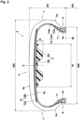
- FIG. 2 is a tire meridian cross-sectional view of the pneumatic tire 3 in the standardized state of the present embodiment.
- the pneumatic tire 3 of the present embodiment includes a tread portion 6, a pair of sidewall portions 7, and a pair of bead portions 8.
- the tread portion 6 has a ground-contact surface 6s which comes into contact with a road surface during rolling.
- the pair of sidewall portions 7 extend inward in the tire radial direction from both sides in the tire axial direction of the tread portion 6, respectively.
- the pair of bead portions 8 are located inward of the sidewall portions 7 in the tire radial direction, respectively, and come into contact with the rim 2 when mounted on the rim 2.
- the ratio SH/SW of a cross-sectional height SH to a tire cross-sectional width SW of the pneumatic tire 3 of the present embodiment is 30% to 45%.
- Such a pneumatic tire 3 can increase the volume of a tire inner cavity 1c while reducing the tire outer diameter, and can be suitably used, for example, as a high-load small-diameter tire required for a low-floor small bus.
- the tire cross-sectional width SW is the width in the tire axial direction at a maximum width position of the sidewall portions 7, not including protruding portions, such as letters and patterns, and a rim guard 3a.
- the cross-sectional height SH is the height in the tire radial direction from a bead base line BL for defining the rim diameter RD to the ground-contact surface 6s at a tire equator C.
- the tire inner cavity 1c is a space defined by an outer surface 2s of the rim 2 and an inner surface 3s of the pneumatic tire 3.
- the ratio RW/SW of a rim width RW of the rim 2 to the tire cross-sectional width SW is preferably 78% to 99%.
- Such a rim 2 serves to increase the volume of the tire inner cavity 1c since the rim width RW is large relative to the tire cross-sectional width SW.
- a sound damper 9 is provided in the tire inner cavity 1c of the present embodiment so as to extend in the tire circumferential direction.
- the sound damper 9 includes a sponge material 9a adhered to at least one of the outer surface 2s of the rim 2 and the inner surface 3s of the pneumatic tire 3, in the present embodiment, to the inner surface 3s of the pneumatic tire 3.
- Such a sound damper 9 can suppress cavity resonance sound generated in the tire inner cavity 1c and reduce the road noise of the tire assembly 1.
- the sponge material 9a of the present embodiment has a volume of not less than 0.4% of the total volume of the tire inner cavity 1c. Such a sponge material 9a can reliably achieve the effect of reducing road noise by the sound damper 9. Therefore, the tire assembly 1 of the present embodiment can reduce road noise even in the case of a high-load small-diameter tire.
- the volume of the sponge material 9a is an apparent volume obtained from the outer shape of the sponge material 9a including the space inside the sponge material 9a, and is a value measured in a state where the pneumatic tire 3 is removed from the rim 2.
- the total volume of the tire inner cavity 1c corresponds to the volume in the standardized state of the tire inner cavity 1c in a state where the sponge material 9a is not provided therein.
- the volume of the sponge material 9a is not greater than 20% of the total volume of the tire inner cavity 1c.
- Such a sponge material 9a can both reduce both the cost of the tire assembly 1 and the road noise of the tire assembly 1.
- the sponge material 9a is preferably placed at a center position in the tire axial direction of the tire inner cavity 1c, including a position on the tire equator C.
- Such a sponge material 9a can efficiently suppress cavity resonance sound generated near the tire equator C at which vibration due to input from a road surface is the largest.
- the ratio W/SW of a width W in the tire axial direction of the sponge material 9a to the tire cross-sectional width SW is preferably 10% to 70%.
- the ratio W/SW is not less than 10%, the effect of reducing road noise by the sound damper 9 can be reliably achieved.
- the ratio W/SW is not greater than 70%, both reduction of the cost of the tire assembly 1 and reduction of the road noise of the tire assembly 1 can be achieved.
- the lower limit of the maximum height H of the sponge material 9a is not particularly limited, but is preferably not less than 10 mm in order to reliably achieve the effect of reducing road noise by the sound damper 9.
- the maximum height H of the sponge material 9a is a value measured in a state where the pneumatic tire 3 is removed from the rim 2.
- the sponge material 9a preferably has a hardness of 10 to 250 N.
- the hardness of the sponge material 9a is not less than 10 N, cavity resonance sound can be efficiently suppressed.
- the hardness of the sponge material 9a is not greater than 250 N, even if the sponge material 9a is adhered to the inner surface 3s of the pneumatic tire 3, the sponge material 9a can follow deformation caused by contact of the ground-contact surface 6s with the ground and suppress peeling.
- the hardness of the sponge material 9a is a value measured according to the method A specified in JIS K6400-2.
- the sponge material 9a preferably has a tensile strength of not less than 70 kPa.
- the tensile strength of the sponge material 9a is not less than 70 kPa, even if the sponge material 9a is adhered to the inner surface 3s of the pneumatic tire 3 and becomes deformed due to contact of the ground-contact surface 6s with the ground, the sponge material 9a is not damaged, and the durability of the sponge material 9a can be improved.
- the tensile strength of the sponge material 9a is a value measured according to the standards of JIS K6400-5.
- the sponge material 9a preferably has a specific gravity of 0.014 to 0.052.
- the specific gravity of the sponge material 9a is not less than 0.014, cavity resonance sound can be efficiently suppressed.
- the specific gravity of the sponge material 9a is not greater than 0.052, weight increase can be suppressed.
- the specific gravity of the sponge material 9a is a value converted from an apparent density measured according to JIS K7222.
- the sound damper 9 includes, for example, an adhesive layer 9b for adhering the sponge material 9a to the outer surface 2s of the rim 2 or the inner surface 3s of the pneumatic tire 3. Such a sound damper 9 can be firmly adhered to the outer surface 2s of the rim 2 or the inner surface 3s of the pneumatic tire 3, thereby improving the durability of the sound damper 9.
- a cross-sectional shape of the sponge material 9a is a shape having two protruding portions in FIG. 2 , but is not limited to such a shape, and may be, for example, a rectangular shape, or may be a semicircular shape, a trapezoidal shape, a triangular shape, or the like.
- FIG. 3 is an end view of the tire assembly 1 at the tire equator C.
- the sponge material 9a of the present embodiment is partially provided in the tire circumferential direction. Such a sponge material 9a can suppress weight increase and reduce the cost.
- a total sum ⁇ of angles ⁇ in the tire circumferential direction over which the sponge material 9a is provided is preferably 108 to 270°.
- the total sum ⁇ is not less than 108°, cavity resonance sound can be reliably suppressed.
- the total sum ⁇ is not greater than 270°, weight increase can be suppressed and the cost can be reduced.
- each bead portion 8 includes, for example, an annular bead core 10 extending in the tire circumferential direction, and a bead apex 11 extending outward in the tire radial direction from the bead core 10.
- the bead core 10 is formed, for example, from a steel wire.
- the bead apex 11 is formed, for example, from a hard rubber.
- Such a bead portion 8 has high stiffness, which serves to suppress deformation in a load-applied state and reduce the road noise of the tire assembly 1.
- the pneumatic tire 3 of the present embodiment includes a carcass 12 extending between the pair of bead portions 8, and a belt layer 13 provided in the tread portion 6.
- the belt layer 13 is provided, for example, outward of the carcass 12 in the tire radial direction.
- the carcass 12 includes at least one carcass ply, in the present embodiment, one carcass ply 12A.
- the carcass ply 12A preferably includes a body portion 12a extending from the tread portion 6 through the sidewall portions 7 to the bead cores 10 of the bead portions 8, and turned-up portions 12b connected to the body portion 12a and turned up around the bead cores 10 from the inner side to the outer side in the tire axial direction.
- Such a carcass 12 serves to improve the stiffness of each bead portion 8 and reduce the road noise of the tire assembly 1.
- the belt layer 13 includes at least one belt ply, preferably includes two or more belt plies, and includes two belt plies 13A and 13B in the present embodiment.
- the two belt plies 13A and 13B include, for example, a first belt ply 13A located on the inner side in the tire radial direction and a second belt ply 13B located outward of the first belt ply 13A.
- Such a belt layer 13 can improve the stiffness of the tread portion 6 and can reduce the road noise of the tire assembly 1.
- the belt plies 13A and 13B each include, for example, a belt cord (not shown) composed of a steel cord.
- the belt cord may be, for example, a single steel wire or a twisted wire obtained by twisting a plurality of steel filaments together.
- the belt cord is arranged, for example, at an angle of 10 to 30° with respect to the tire circumferential direction.
- the belt cord of the first belt ply 13A and the belt cord of the second belt ply 13B are preferably tilted relative to the tire circumferential direction in directions opposite to each other.
- Such a belt layer 13 can increase the stiffness of the tread portion 6 in a well-balanced manner and reduce the road noise of the tire assembly 1.
- the angle of each belt cord is an angle in the pneumatic tire 3 in the standardized state, and can be confirmed, for example, by partially peeling off the tread portion 6.
- the present invention is as follows.
- a tire assembly including a rim and a pneumatic tire mounted on the rim, wherein
Landscapes
- Engineering & Computer Science (AREA)
- Mechanical Engineering (AREA)
- Tires In General (AREA)
Applications Claiming Priority (1)
| Application Number | Priority Date | Filing Date | Title |
|---|---|---|---|
| JP2023045745A JP2024135183A (ja) | 2023-03-22 | 2023-03-22 | タイヤ組立体 |
Publications (1)
| Publication Number | Publication Date |
|---|---|
| EP4434775A1 true EP4434775A1 (de) | 2024-09-25 |
Family
ID=89900787
Family Applications (1)
| Application Number | Title | Priority Date | Filing Date |
|---|---|---|---|
| EP24156829.4A Pending EP4434775A1 (de) | 2023-03-22 | 2024-02-09 | Reifenanordnung |
Country Status (3)
| Country | Link |
|---|---|
| US (1) | US20240316997A1 (de) |
| EP (1) | EP4434775A1 (de) |
| JP (1) | JP2024135183A (de) |
Citations (4)
| Publication number | Priority date | Publication date | Assignee | Title |
|---|---|---|---|---|
| EP1253025A2 (de) * | 2001-04-16 | 2002-10-30 | Sumitomo Rubber Industries Ltd. | Reifengeräusch reduzierende Vorrichtung |
| EP1529665A1 (de) * | 2003-11-07 | 2005-05-11 | Sumitomo Rubber Industries Limited | Schallabsorbierendes System bei Fahrzeugreifen |
| EP1607243A1 (de) * | 2004-06-14 | 2005-12-21 | Sumitomo Rubber Industries, Ltd. | Geräuschreduzierendes System für Fahrzeugreifen |
| JP2006306302A (ja) | 2005-04-28 | 2006-11-09 | Sumitomo Rubber Ind Ltd | 空気入りタイヤとリムとの組立体 |
-
2023
- 2023-03-22 JP JP2023045745A patent/JP2024135183A/ja active Pending
-
2024
- 2024-02-07 US US18/434,865 patent/US20240316997A1/en active Pending
- 2024-02-09 EP EP24156829.4A patent/EP4434775A1/de active Pending
Patent Citations (4)
| Publication number | Priority date | Publication date | Assignee | Title |
|---|---|---|---|---|
| EP1253025A2 (de) * | 2001-04-16 | 2002-10-30 | Sumitomo Rubber Industries Ltd. | Reifengeräusch reduzierende Vorrichtung |
| EP1529665A1 (de) * | 2003-11-07 | 2005-05-11 | Sumitomo Rubber Industries Limited | Schallabsorbierendes System bei Fahrzeugreifen |
| EP1607243A1 (de) * | 2004-06-14 | 2005-12-21 | Sumitomo Rubber Industries, Ltd. | Geräuschreduzierendes System für Fahrzeugreifen |
| JP2006306302A (ja) | 2005-04-28 | 2006-11-09 | Sumitomo Rubber Ind Ltd | 空気入りタイヤとリムとの組立体 |
Also Published As
| Publication number | Publication date |
|---|---|
| US20240316997A1 (en) | 2024-09-26 |
| JP2024135183A (ja) | 2024-10-04 |
Similar Documents
| Publication | Publication Date | Title |
|---|---|---|
| JP4170821B2 (ja) | 空気入りラジアルタイヤ | |
| EP3885160B1 (de) | Reifen | |
| US9272582B2 (en) | Pneumatic tire | |
| JPWO2003035413A1 (ja) | 空気入りタイヤ | |
| JP3540966B2 (ja) | 空気入りラジアルタイヤ | |
| JP4728304B2 (ja) | 空気入りタイヤ | |
| US20200016934A1 (en) | Heavy duty pneumatic tire | |
| EP1683654B1 (de) | Notlaufreifen | |
| JP2023018528A (ja) | タイヤ | |
| JP2002120514A (ja) | 空気入りタイヤ | |
| CN100357119C (zh) | 充气轮胎 | |
| JPH07304307A (ja) | タイヤ用補強コード及びそれを用いた空気入りタイヤ | |
| JP2023002263A (ja) | タイヤ | |
| JP2007290578A (ja) | レース用空気入りタイヤ | |
| JP4583891B2 (ja) | 自動二輪車用タイヤ | |
| EP2602125B1 (de) | Luftreifen | |
| JP2004203129A (ja) | 空気入りラジアルタイヤ | |
| US20240316997A1 (en) | Tire assembly | |
| JP6529127B2 (ja) | 空気入りタイヤ | |
| US20240294040A1 (en) | Pneumatic tire | |
| JP4515124B2 (ja) | 空気入りタイヤ | |
| JPH0274403A (ja) | 空気入りタイヤ | |
| US20250153515A1 (en) | Tire | |
| EP4570532A1 (de) | Luftreifen | |
| JP7848508B2 (ja) | 制音体付き空気入りタイヤ |
Legal Events
| Date | Code | Title | Description |
|---|---|---|---|
| PUAI | Public reference made under article 153(3) epc to a published international application that has entered the european phase |
Free format text: ORIGINAL CODE: 0009012 |
|
| STAA | Information on the status of an ep patent application or granted ep patent |
Free format text: STATUS: THE APPLICATION HAS BEEN PUBLISHED |
|
| AK | Designated contracting states |
Kind code of ref document: A1 Designated state(s): AL AT BE BG CH CY CZ DE DK EE ES FI FR GB GR HR HU IE IS IT LI LT LU LV MC ME MK MT NL NO PL PT RO RS SE SI SK SM TR |
|
| STAA | Information on the status of an ep patent application or granted ep patent |
Free format text: STATUS: REQUEST FOR EXAMINATION WAS MADE |
|
| 17P | Request for examination filed |
Effective date: 20250220 |
|
| P01 | Opt-out of the competence of the unified patent court (upc) registered |
Free format text: CASE NUMBER: APP_12416/2025 Effective date: 20250313 |
|
| STAA | Information on the status of an ep patent application or granted ep patent |
Free format text: STATUS: EXAMINATION IS IN PROGRESS |
|
| 17Q | First examination report despatched |
Effective date: 20251125 |