EP4438367A1 - Verfahren und vorrichtung zur kühlung des motorantriebsstillstands für fahrzeug und fahrzeug - Google Patents
Verfahren und vorrichtung zur kühlung des motorantriebsstillstands für fahrzeug und fahrzeug Download PDFInfo
- Publication number
- EP4438367A1 EP4438367A1 EP23759259.7A EP23759259A EP4438367A1 EP 4438367 A1 EP4438367 A1 EP 4438367A1 EP 23759259 A EP23759259 A EP 23759259A EP 4438367 A1 EP4438367 A1 EP 4438367A1
- Authority
- EP
- European Patent Office
- Prior art keywords
- preset
- driving motor
- vehicle
- engine
- cooling
- Prior art date
- Legal status (The legal status is an assumption and is not a legal conclusion. Google has not performed a legal analysis and makes no representation as to the accuracy of the status listed.)
- Granted
Links
Images

Classifications
-
- B—PERFORMING OPERATIONS; TRANSPORTING
- B60—VEHICLES IN GENERAL
- B60K—ARRANGEMENT OR MOUNTING OF PROPULSION UNITS OR OF TRANSMISSIONS IN VEHICLES; ARRANGEMENT OR MOUNTING OF PLURAL DIVERSE PRIME-MOVERS IN VEHICLES; AUXILIARY DRIVES FOR VEHICLES; INSTRUMENTATION OR DASHBOARDS FOR VEHICLES; ARRANGEMENTS IN CONNECTION WITH COOLING, AIR INTAKE, GAS EXHAUST OR FUEL SUPPLY OF PROPULSION UNITS IN VEHICLES
- B60K11/00—Arrangement in connection with cooling of propulsion units
- B60K11/06—Arrangement in connection with cooling of propulsion units with air cooling
-
- B—PERFORMING OPERATIONS; TRANSPORTING
- B60—VEHICLES IN GENERAL
- B60K—ARRANGEMENT OR MOUNTING OF PROPULSION UNITS OR OF TRANSMISSIONS IN VEHICLES; ARRANGEMENT OR MOUNTING OF PLURAL DIVERSE PRIME-MOVERS IN VEHICLES; AUXILIARY DRIVES FOR VEHICLES; INSTRUMENTATION OR DASHBOARDS FOR VEHICLES; ARRANGEMENTS IN CONNECTION WITH COOLING, AIR INTAKE, GAS EXHAUST OR FUEL SUPPLY OF PROPULSION UNITS IN VEHICLES
- B60K11/00—Arrangement in connection with cooling of propulsion units
- B60K11/02—Arrangement in connection with cooling of propulsion units with liquid cooling
-
- B—PERFORMING OPERATIONS; TRANSPORTING
- B60—VEHICLES IN GENERAL
- B60K—ARRANGEMENT OR MOUNTING OF PROPULSION UNITS OR OF TRANSMISSIONS IN VEHICLES; ARRANGEMENT OR MOUNTING OF PLURAL DIVERSE PRIME-MOVERS IN VEHICLES; AUXILIARY DRIVES FOR VEHICLES; INSTRUMENTATION OR DASHBOARDS FOR VEHICLES; ARRANGEMENTS IN CONNECTION WITH COOLING, AIR INTAKE, GAS EXHAUST OR FUEL SUPPLY OF PROPULSION UNITS IN VEHICLES
- B60K6/00—Arrangement or mounting of plural diverse prime-movers for mutual or common propulsion, e.g. hybrid propulsion systems comprising electric motors and internal combustion engines
- B60K6/20—Arrangement or mounting of plural diverse prime-movers for mutual or common propulsion, e.g. hybrid propulsion systems comprising electric motors and internal combustion engines the prime-movers consisting of electric motors and internal combustion engines, e.g. HEVs
- B60K6/22—Arrangement or mounting of plural diverse prime-movers for mutual or common propulsion, e.g. hybrid propulsion systems comprising electric motors and internal combustion engines the prime-movers consisting of electric motors and internal combustion engines, e.g. HEVs characterised by apparatus, components or means specially adapted for HEVs
-
- B—PERFORMING OPERATIONS; TRANSPORTING
- B60—VEHICLES IN GENERAL
- B60W—CONJOINT CONTROL OF VEHICLE SUB-UNITS OF DIFFERENT TYPE OR DIFFERENT FUNCTION; CONTROL SYSTEMS SPECIALLY ADAPTED FOR HYBRID VEHICLES; ROAD VEHICLE DRIVE CONTROL SYSTEMS FOR PURPOSES NOT RELATED TO THE CONTROL OF A PARTICULAR SUB-UNIT
- B60W10/00—Conjoint control of vehicle sub-units of different type or different function
- B60W10/04—Conjoint control of vehicle sub-units of different type or different function including control of propulsion units
- B60W10/06—Conjoint control of vehicle sub-units of different type or different function including control of propulsion units including control of combustion engines
-
- B—PERFORMING OPERATIONS; TRANSPORTING
- B60—VEHICLES IN GENERAL
- B60W—CONJOINT CONTROL OF VEHICLE SUB-UNITS OF DIFFERENT TYPE OR DIFFERENT FUNCTION; CONTROL SYSTEMS SPECIALLY ADAPTED FOR HYBRID VEHICLES; ROAD VEHICLE DRIVE CONTROL SYSTEMS FOR PURPOSES NOT RELATED TO THE CONTROL OF A PARTICULAR SUB-UNIT
- B60W10/00—Conjoint control of vehicle sub-units of different type or different function
- B60W10/04—Conjoint control of vehicle sub-units of different type or different function including control of propulsion units
- B60W10/08—Conjoint control of vehicle sub-units of different type or different function including control of propulsion units including control of electric propulsion units, e.g. motors or generators
-
- B—PERFORMING OPERATIONS; TRANSPORTING
- B60—VEHICLES IN GENERAL
- B60W—CONJOINT CONTROL OF VEHICLE SUB-UNITS OF DIFFERENT TYPE OR DIFFERENT FUNCTION; CONTROL SYSTEMS SPECIALLY ADAPTED FOR HYBRID VEHICLES; ROAD VEHICLE DRIVE CONTROL SYSTEMS FOR PURPOSES NOT RELATED TO THE CONTROL OF A PARTICULAR SUB-UNIT
- B60W10/00—Conjoint control of vehicle sub-units of different type or different function
- B60W10/30—Conjoint control of vehicle sub-units of different type or different function including control of auxiliary equipment, e.g. air-conditioning compressors or oil pumps
-
- B—PERFORMING OPERATIONS; TRANSPORTING
- B60—VEHICLES IN GENERAL
- B60W—CONJOINT CONTROL OF VEHICLE SUB-UNITS OF DIFFERENT TYPE OR DIFFERENT FUNCTION; CONTROL SYSTEMS SPECIALLY ADAPTED FOR HYBRID VEHICLES; ROAD VEHICLE DRIVE CONTROL SYSTEMS FOR PURPOSES NOT RELATED TO THE CONTROL OF A PARTICULAR SUB-UNIT
- B60W20/00—Control systems specially adapted for hybrid vehicles
-
- B—PERFORMING OPERATIONS; TRANSPORTING
- B60—VEHICLES IN GENERAL
- B60W—CONJOINT CONTROL OF VEHICLE SUB-UNITS OF DIFFERENT TYPE OR DIFFERENT FUNCTION; CONTROL SYSTEMS SPECIALLY ADAPTED FOR HYBRID VEHICLES; ROAD VEHICLE DRIVE CONTROL SYSTEMS FOR PURPOSES NOT RELATED TO THE CONTROL OF A PARTICULAR SUB-UNIT
- B60W20/00—Control systems specially adapted for hybrid vehicles
- B60W20/40—Controlling the engagement or disengagement of prime movers, e.g. for transition between prime movers
-
- B—PERFORMING OPERATIONS; TRANSPORTING
- B60—VEHICLES IN GENERAL
- B60K—ARRANGEMENT OR MOUNTING OF PROPULSION UNITS OR OF TRANSMISSIONS IN VEHICLES; ARRANGEMENT OR MOUNTING OF PLURAL DIVERSE PRIME-MOVERS IN VEHICLES; AUXILIARY DRIVES FOR VEHICLES; INSTRUMENTATION OR DASHBOARDS FOR VEHICLES; ARRANGEMENTS IN CONNECTION WITH COOLING, AIR INTAKE, GAS EXHAUST OR FUEL SUPPLY OF PROPULSION UNITS IN VEHICLES
- B60K1/00—Arrangement or mounting of electrical propulsion units
- B60K2001/003—Arrangement or mounting of electrical propulsion units with means for cooling the electrical propulsion units
- B60K2001/006—Arrangement or mounting of electrical propulsion units with means for cooling the electrical propulsion units the electric motors
-
- B—PERFORMING OPERATIONS; TRANSPORTING
- B60—VEHICLES IN GENERAL
- B60W—CONJOINT CONTROL OF VEHICLE SUB-UNITS OF DIFFERENT TYPE OR DIFFERENT FUNCTION; CONTROL SYSTEMS SPECIALLY ADAPTED FOR HYBRID VEHICLES; ROAD VEHICLE DRIVE CONTROL SYSTEMS FOR PURPOSES NOT RELATED TO THE CONTROL OF A PARTICULAR SUB-UNIT
- B60W50/00—Details of control systems for road vehicle drive control not related to the control of a particular sub-unit, e.g. process diagnostic or vehicle driver interfaces
- B60W2050/0062—Adapting control system settings
- B60W2050/0075—Automatic parameter input, automatic initialising or calibrating means
- B60W2050/0083—Setting, resetting, calibration
-
- B—PERFORMING OPERATIONS; TRANSPORTING
- B60—VEHICLES IN GENERAL
- B60W—CONJOINT CONTROL OF VEHICLE SUB-UNITS OF DIFFERENT TYPE OR DIFFERENT FUNCTION; CONTROL SYSTEMS SPECIALLY ADAPTED FOR HYBRID VEHICLES; ROAD VEHICLE DRIVE CONTROL SYSTEMS FOR PURPOSES NOT RELATED TO THE CONTROL OF A PARTICULAR SUB-UNIT
- B60W2400/00—Indexing codes relating to detected, measured or calculated conditions or factors
-
- B—PERFORMING OPERATIONS; TRANSPORTING
- B60—VEHICLES IN GENERAL
- B60W—CONJOINT CONTROL OF VEHICLE SUB-UNITS OF DIFFERENT TYPE OR DIFFERENT FUNCTION; CONTROL SYSTEMS SPECIALLY ADAPTED FOR HYBRID VEHICLES; ROAD VEHICLE DRIVE CONTROL SYSTEMS FOR PURPOSES NOT RELATED TO THE CONTROL OF A PARTICULAR SUB-UNIT
- B60W2510/00—Input parameters relating to a particular sub-units
- B60W2510/08—Electric propulsion units
- B60W2510/083—Torque
-
- B—PERFORMING OPERATIONS; TRANSPORTING
- B60—VEHICLES IN GENERAL
- B60W—CONJOINT CONTROL OF VEHICLE SUB-UNITS OF DIFFERENT TYPE OR DIFFERENT FUNCTION; CONTROL SYSTEMS SPECIALLY ADAPTED FOR HYBRID VEHICLES; ROAD VEHICLE DRIVE CONTROL SYSTEMS FOR PURPOSES NOT RELATED TO THE CONTROL OF A PARTICULAR SUB-UNIT
- B60W2510/00—Input parameters relating to a particular sub-units
- B60W2510/08—Electric propulsion units
- B60W2510/087—Temperature
-
- B—PERFORMING OPERATIONS; TRANSPORTING
- B60—VEHICLES IN GENERAL
- B60W—CONJOINT CONTROL OF VEHICLE SUB-UNITS OF DIFFERENT TYPE OR DIFFERENT FUNCTION; CONTROL SYSTEMS SPECIALLY ADAPTED FOR HYBRID VEHICLES; ROAD VEHICLE DRIVE CONTROL SYSTEMS FOR PURPOSES NOT RELATED TO THE CONTROL OF A PARTICULAR SUB-UNIT
- B60W2510/00—Input parameters relating to a particular sub-units
- B60W2510/10—Change speed gearings
- B60W2510/1005—Transmission ratio engaged
-
- B—PERFORMING OPERATIONS; TRANSPORTING
- B60—VEHICLES IN GENERAL
- B60W—CONJOINT CONTROL OF VEHICLE SUB-UNITS OF DIFFERENT TYPE OR DIFFERENT FUNCTION; CONTROL SYSTEMS SPECIALLY ADAPTED FOR HYBRID VEHICLES; ROAD VEHICLE DRIVE CONTROL SYSTEMS FOR PURPOSES NOT RELATED TO THE CONTROL OF A PARTICULAR SUB-UNIT
- B60W2510/00—Input parameters relating to a particular sub-units
- B60W2510/30—Auxiliary equipments
-
- B—PERFORMING OPERATIONS; TRANSPORTING
- B60—VEHICLES IN GENERAL
- B60W—CONJOINT CONTROL OF VEHICLE SUB-UNITS OF DIFFERENT TYPE OR DIFFERENT FUNCTION; CONTROL SYSTEMS SPECIALLY ADAPTED FOR HYBRID VEHICLES; ROAD VEHICLE DRIVE CONTROL SYSTEMS FOR PURPOSES NOT RELATED TO THE CONTROL OF A PARTICULAR SUB-UNIT
- B60W2520/00—Input parameters relating to overall vehicle dynamics
- B60W2520/04—Vehicle stop
-
- B—PERFORMING OPERATIONS; TRANSPORTING
- B60—VEHICLES IN GENERAL
- B60W—CONJOINT CONTROL OF VEHICLE SUB-UNITS OF DIFFERENT TYPE OR DIFFERENT FUNCTION; CONTROL SYSTEMS SPECIALLY ADAPTED FOR HYBRID VEHICLES; ROAD VEHICLE DRIVE CONTROL SYSTEMS FOR PURPOSES NOT RELATED TO THE CONTROL OF A PARTICULAR SUB-UNIT
- B60W2520/00—Input parameters relating to overall vehicle dynamics
- B60W2520/10—Longitudinal speed
-
- B—PERFORMING OPERATIONS; TRANSPORTING
- B60—VEHICLES IN GENERAL
- B60W—CONJOINT CONTROL OF VEHICLE SUB-UNITS OF DIFFERENT TYPE OR DIFFERENT FUNCTION; CONTROL SYSTEMS SPECIALLY ADAPTED FOR HYBRID VEHICLES; ROAD VEHICLE DRIVE CONTROL SYSTEMS FOR PURPOSES NOT RELATED TO THE CONTROL OF A PARTICULAR SUB-UNIT
- B60W2710/00—Output or target parameters relating to a particular sub-units
- B60W2710/06—Combustion engines, Gas turbines
- B60W2710/0644—Engine speed
-
- B—PERFORMING OPERATIONS; TRANSPORTING
- B60—VEHICLES IN GENERAL
- B60W—CONJOINT CONTROL OF VEHICLE SUB-UNITS OF DIFFERENT TYPE OR DIFFERENT FUNCTION; CONTROL SYSTEMS SPECIALLY ADAPTED FOR HYBRID VEHICLES; ROAD VEHICLE DRIVE CONTROL SYSTEMS FOR PURPOSES NOT RELATED TO THE CONTROL OF A PARTICULAR SUB-UNIT
- B60W2710/00—Output or target parameters relating to a particular sub-units
- B60W2710/06—Combustion engines, Gas turbines
- B60W2710/0677—Engine power
-
- B—PERFORMING OPERATIONS; TRANSPORTING
- B60—VEHICLES IN GENERAL
- B60W—CONJOINT CONTROL OF VEHICLE SUB-UNITS OF DIFFERENT TYPE OR DIFFERENT FUNCTION; CONTROL SYSTEMS SPECIALLY ADAPTED FOR HYBRID VEHICLES; ROAD VEHICLE DRIVE CONTROL SYSTEMS FOR PURPOSES NOT RELATED TO THE CONTROL OF A PARTICULAR SUB-UNIT
- B60W2710/00—Output or target parameters relating to a particular sub-units
- B60W2710/30—Auxiliary equipments
-
- B—PERFORMING OPERATIONS; TRANSPORTING
- B60—VEHICLES IN GENERAL
- B60W—CONJOINT CONTROL OF VEHICLE SUB-UNITS OF DIFFERENT TYPE OR DIFFERENT FUNCTION; CONTROL SYSTEMS SPECIALLY ADAPTED FOR HYBRID VEHICLES; ROAD VEHICLE DRIVE CONTROL SYSTEMS FOR PURPOSES NOT RELATED TO THE CONTROL OF A PARTICULAR SUB-UNIT
- B60W30/00—Purposes of road vehicle drive control systems not related to the control of a particular sub-unit, e.g. of systems using conjoint control of vehicle sub-units
- B60W30/18—Propelling the vehicle
- B60W30/18009—Propelling the vehicle related to particular drive situations
- B60W30/18063—Creeping
-
- B—PERFORMING OPERATIONS; TRANSPORTING
- B60—VEHICLES IN GENERAL
- B60Y—INDEXING SCHEME RELATING TO ASPECTS CROSS-CUTTING VEHICLE TECHNOLOGY
- B60Y2200/00—Type of vehicle
- B60Y2200/90—Vehicles comprising electric prime movers
- B60Y2200/92—Hybrid vehicles
-
- Y—GENERAL TAGGING OF NEW TECHNOLOGICAL DEVELOPMENTS; GENERAL TAGGING OF CROSS-SECTIONAL TECHNOLOGIES SPANNING OVER SEVERAL SECTIONS OF THE IPC; TECHNICAL SUBJECTS COVERED BY FORMER USPC CROSS-REFERENCE ART COLLECTIONS [XRACs] AND DIGESTS
- Y02—TECHNOLOGIES OR APPLICATIONS FOR MITIGATION OR ADAPTATION AGAINST CLIMATE CHANGE
- Y02T—CLIMATE CHANGE MITIGATION TECHNOLOGIES RELATED TO TRANSPORTATION
- Y02T10/00—Road transport of goods or passengers
- Y02T10/60—Other road transportation technologies with climate change mitigation effect
- Y02T10/62—Hybrid vehicles
Definitions
- the present disclosure relates to the field of vehicle heat dissipation, and specifically, to a method and device for cooling a locked rotor driving motor of a vehicle and a vehicle.
- a cooling system is driven by the electric oil pump, and can cool a driving motor under full working conditions.
- the cooling of the driving motor mainly depends on rotation of a wheel to drive a wheel end oil pump to perform a cooling operation.
- a locked rotor of the driving motor may lead to a low vehicle speed, and then the wheel end oil pump has a low rotational speed to make it impossible to provide a sufficient coolant to cool the driving motor. As a result, the service life of the driving motor is reduced or the driving motor is even burnt out.
- An objective of the present disclosure is to provide a method and device for cooling a locked rotor driving motor of a vehicle and a vehicle, to solve the technical problem that when a locked rotor occurs to a driving motor in an electric vehicle mode, it is impossible to provide a sufficient coolant to cool the driving motor.
- a first aspect of the present disclosure provides a method for cooling a locked rotor driving motor of a vehicle.
- the vehicle includes a driving motor, an engine, an engine end oil pump, and a cooling flow path.
- the engine is configured to drive the engine end oil pump to run, and the cooling flow path connects the engine end oil pump to the driving motor.
- the method includes the following:
- a driving mode of the vehicle is an electric vehicle mode
- the vehicle meets a preset locked rotor motor activation condition, and a current temperature of the driving motor is greater than an auxiliary cooling starting temperature of the engine
- the engine of the vehicle is controlled to start, to cause the engine end oil pump of the vehicle to drive a coolant in the cooling flow path to cool the driving motor.
- the method further includes the following:
- auxiliary cooling starting temperature of the engine is reduced includes the following:
- the auxiliary cooling starting temperature of the engine is reduced includes the following: If the first duration is less than or equal to first preset duration, the auxiliary cooling starting temperature of the engine is equal to a second preset temperature, where the second preset temperature is less than the first preset temperature.
- the method further includes the following: If the first duration is greater than the first preset duration, the auxiliary cooling starting temperature of the engine is equal to the first preset temperature.
- the method further includes the following: If the vehicle meets a preset locked rotor motor exit condition and it is determined that the current temperature of the driving motor is less than an auxiliary cooling shutdown temperature of the engine, the engine is controlled to stop running after second preset duration.
- the first preset temperature is a maximum allowable temperature of the driving motor
- the second preset temperature is a safe starting temperature of the driving motor under a locked rotor working condition
- the auxiliary cooling starting temperature of the engine is less than or equal to the first preset temperature
- the method further includes the following:
- the method further includes the following:
- that the engine of the vehicle is controlled to start includes the following:
- the method further includes the following:
- the preset locked rotor motor activation condition includes: a gear of the vehicle is in a forward gear or a reverse gear, a torque of the driving motor is greater than or equal to a first preset torque, and a vehicle speed of the vehicle is less than or equal to a first preset vehicle speed; and
- the vehicle includes a spill valve, and the spill valve is configured to control a flow rate in the cooling flow path.
- the method further includes the following: After the engine is started to cool the driving motor, if the flow rate of flowing through the cooling flow path of the driving motor is greater than a third preset cooling flow rate, the spill valve of the vehicle is requested to enter a forcibly closed state.
- a second aspect of the present disclosure further provides a device for cooling a locked rotor driving motor of a vehicle.
- the vehicle includes a driving motor, an engine, an engine end oil pump, and a cooling flow path.
- the engine is configured to drive the engine end oil pump to run, and the cooling flow path connects the engine end oil pump to the driving motor.
- the device includes: a controller, configured to implement the steps of the method for cooling a locked rotor driving motor of a vehicle according to any one of the implementations of the first aspect described above.
- a third aspect of the present disclosure further provides a non-transitory computer-readable storage medium, having a computer program stored thereon.
- the program when executed by a processor, implements the steps of the method for cooling a locked rotor driving motor of a vehicle according to any one of the implementations of the first aspect described above.
- a fourth aspect of the present disclosure further provides a vehicle, including a driving motor, an engine, an engine end oil pump, a cooling flow path, and a controller.
- the engine is configured to drive the engine end oil pump to run.
- the cooling flow path connects the engine end oil pump to the driving motor.
- the controller is configured to implement the steps of the method for cooling a locked rotor driving motor of a vehicle according to any one of the implementations of the first aspect described above.
- a driving mode of the vehicle is an electric vehicle mode
- the vehicle meets a preset locked rotor motor activation condition, and a current temperature of the driving motor is greater than an auxiliary cooling starting temperature of the engine
- the engine of the vehicle is controlled to start, to cause the engine end oil pump of the vehicle to drive a coolant in the cooling flow path to cool the driving motor.
- FIG. 1 a cooling system architecture of a hybrid vehicle without an electric oil pump is shown in FIG. 1 .
- a wheel end oil pump 101 and an engine end oil pump 102 are mechanical pumps.
- the wheel end oil pump 101 is driven by rotation of a wheel and is responsible for a low-pressure oil circuit (cooling and lubrication), while the engine end oil pump 102 is driven by rotation of an engine and is responsible for oil supply of a high-pressure oil circuit (hydraulic pressure of a clutch 108, and the like).
- a control valve 103 is arranged between the low-pressure oil circuit and the high-pressure oil circuit, and the control valve 103 includes at least a first state in which the engine end oil pump 102 is allowed to supply oil to a cooling oil circuit of a driving motor 104 and a second state in which the oil supply is off.
- the wheel end oil pump 101 is driven to perform a cooling operation mainly by the rotation of a wheel.
- the engine end oil pump 102 is driven by the engine to perform a cooling operation with the wheel end oil pump 101.
- a cooling fan 105 can also cool the driving motor 104 when operating.
- a spill valve 106 is an electromagnetic valve that controls a cooling flow rate of the cooling oil circle.
- the spill valve 106 is opened, allowing only cooling oil (that is, coolant) with a minimum flow rate to flow to the driving motor 104, and the excess part flows back to an oil tank 107.
- the driving motor 104 is shut down when needing to be cooled, and all the cooling oil exchanges heat with the outside through the cooling oil circuit.
- a locked rotor of the driving motor may lead to a low vehicle speed, and then the wheel end oil pump has a low rotational speed to make it impossible to provide a sufficient coolant to cool the driving motor.
- the service life of the driving motor is reduced or the driving motor is even burnt out.
- the present disclosure provides a method and device for cooling a locked rotor driving motor of a vehicle and a vehicle, to solve the above problems.
- An embodiment of the present disclosure provides a method for cooling a locked rotor driving motor of a vehicle.
- the vehicle includes a driving motor, an engine, an engine end oil pump, and a cooling flow path.
- the engine is configured to drive the engine end oil pump to run, and the cooling flow path connects the engine end oil pump to the driving motor.
- the method includes the following steps.
- a driving mode of the vehicle is an electric vehicle mode
- the vehicle meets a preset locked rotor motor activation condition, and a current temperature of the driving motor is greater than an auxiliary cooling starting temperature of the engine
- the engine of the vehicle is controlled to start, to cause the engine end oil pump of the vehicle to drive a coolant in the cooling flow path to cool the driving motor.
- a driving mode of the vehicle is an electric vehicle mode
- the vehicle meets a preset locked rotor motor activation condition, and a current temperature of the driving motor is greater than an auxiliary cooling starting temperature of the engine
- the engine of the vehicle is controlled to start, to cause the engine end oil pump of the vehicle to drive a coolant in the cooling flow path to cool the driving motor.
- the method further includes the following: First duration for a temperature of the driving motor to reach a first preset temperature is determined according to a temperature change rate of the driving motor and the current temperature of the driving motor; and if the first duration is less than or equal to first preset duration, the auxiliary cooling starting temperature of the engine is reduced.
- the auxiliary cooling starting temperature of the engine being reduced may be as follows: If the first duration is less than or equal to the first preset duration, a target correction offset is determined based on the temperature change rate of the driving motor and a preset relationship between the temperature change rate and a correction offset, and then a difference between the first preset temperature and the target correction offset is taken as the auxiliary cooling starting temperature of the engine.
- the auxiliary cooling starting temperature of the engine being reduced may be as follows: If the first duration is less than or equal to first preset duration, the auxiliary cooling starting temperature of the engine is equal to a second preset temperature, where the second preset temperature is less than the first preset temperature.
- the first preset temperature is a maximum allowable temperature of the driving motor
- the second preset temperature is a safe starting temperature of the driving motor under a locked rotor working condition
- the auxiliary cooling starting temperature of the engine is less than or equal to the first preset temperature
- the auxiliary cooling starting temperature of the engine is usually set to a maximum allowable temperature of the driving motor.
- the temperature sensor detects that the current temperature of the driving motor is greater than the maximum allowable temperature, an actual temperature of the driving motor may have been already much greater than the maximum allowable temperature, leading to overheating and burning of the driving motor. Therefore, the auxiliary cooling starting temperature of the engine can be adjusted according to the current temperature change rate and the maximum allowable temperature of the driving motor.
- the auxiliary cooling starting temperature of the engine can be reduced, so that the engine can be started in advance to participate in the cooling of the driving motor, thereby ensuring that the driving motor always operates in a reasonable temperature range and avoiding overheating and burning of the driving motor caused by the response delay of the temperature sensor.
- the preset relationship between the temperature change rate and the correction offset is determined by experiments, which may be shown in Table 1 below.
- the temperature change rate is a temperature change rate of the driving motor every 3 seconds, and is obtained by rounding.
- Table 1 Temperature change rate (°C/3 s) 0 1 2 3 Correction offset A (°C) 0 10 20 30
- the correction offset can be obtained by querying the current temperature change rate detected by the temperature sensor in Table 1.
- the auxiliary cooling starting temperature of the engine is set to the safe starting temperature (second preset temperature), so that the engine can be started in advance to participate in the cooling of the driving motor, thereby ensuring that the driving motor always operates in a reasonable temperature range and avoiding overheating and burning of the driving motor caused by the response delay of the temperature sensor.
- a relationship curve of the current temperature change rate and the auxiliary cooling starting temperature of the engine may be determined by experiments.
- the auxiliary cooling starting temperature of the engine when the current temperature change rate is 0, the auxiliary cooling starting temperature of the engine is equal to the maximum allowable temperature of the driving motor, and a larger current temperature change rate indicates a smaller auxiliary cooling starting temperature of the engine.
- the auxiliary cooling starting temperature of the engine is reduced based on the relationship curve, and the engine can be started in advance to cool the driving motor, to ensure that the driving motor always operates in a reasonable temperature range and avoid overheating and burning of the driving motor caused by the response delay of the temperature sensor.
- the method further includes the following: If the first duration is greater than the first preset duration, the auxiliary cooling starting temperature of the engine is equal to the first preset temperature.
- the driving motor when the duration for the temperature of the driving motor to reach the maximum allowable temperature is greater than the first preset duration, the driving motor is currently subjected to no risk of overheating and burning. Therefore, it is not necessary to start the engine in advance to participate in the cooling of the driving motor, and the auxiliary cooling starting temperature of the engine may be set to be consistent with the maximum allowable temperature.
- the duration for the temperature of the driving motor to reach the maximum allowable temperature is less than or equal to the first preset duration, the driving motor is currently subjected to the risk of overheating and burning.
- the method further includes the following: If the vehicle meets a preset locked rotor motor exit condition and it is determined that the current temperature of the driving motor is less than an auxiliary cooling shutdown temperature of the engine, the engine is controlled to stop running after second preset duration.
- the engine is immediately started to participate in the cooling of the driving motor to avoid overheating and burning of the driving motor. Then, when the vehicle meets the preset cooling exit condition and it is determined that the current temperature of the driving motor is less than the auxiliary cooling shutdown temperature of the engine, that is, when the driving motor no longer needs the engine to participate in cooling, to avoid the loss caused by frequent starting of the engine to the engine, the engine can be shut down after preset duration, so as to prevent a change in vehicle state in a short time, which otherwise results in restarting the engine to cool the driving motor.
- the auxiliary cooling shutdown temperature of the engine is determined according to the physical characteristics of the driving motor, and for example, may be 105°C, and the preset duration may be set according to experiments, and for example, may be 14 s, which is not limited in the present disclosure.
- the method further includes the following: A rotational speed of the engine is controlled based on the current temperature of the driving motor.
- the rotational speed of the engine is positively correlated with the current temperature of the driving motor. If the vehicle meets the preset locked rotor motor activation condition and a flow rate of flowing through the cooling flow path of the driving motor is greater than a first preset cooling flow rate, a cooling fan of the vehicle is controlled to run at a maximum rotational speed to cool the driving motor.
- the method further includes the following: If the vehicle meets a preset locked rotor motor exit condition and a flow rate of flowing through the cooling flow path of the driving motor is less than a second preset cooling flow rate, the cooling fan is controlled to stop running. The first preset cooling flow rate is greater than the second preset cooling flow rate.
- the cooling of the driving motor mainly depends on that the coolant circulates in the cooling flow path, thereby taking away heat generated by the driving motor during the operation, and exchanging heat with the outside through a heat dissipation system.
- the rotational speed of the engine is positively correlated with the current temperature of the driving motor, that is, when the current temperature of the driving motor is higher, faster heat dissipation is needed, so the rotational speed of the engine controlled is higher, and a cooling flow rate driven by the engine end oil pump is larger, thereby taking away more heat.
- a cooling fan of the vehicle is controlled to run at a maximum rotational speed to ensure that the coolant dissipates heat as soon as possible, thereby cooling the driving motor.
- the cooling fan is controlled to stop running. Unnecessary energy consumption caused by the cooling fan always running at the maximum rotational speed is avoided.
- the first preset cooling flow rate and the second preset cooling flow rate may be determined through experiments.
- the first preset cooling flow rate may be 3 L
- the second preset cooling flow rate may be 1.5 L, which is not specifically limited in the present disclosure, provided that it is ensured that the first preset cooling flow rate is greater than the second preset cooling flow rate.
- the engine start of the vehicle may be controlled by the following method: The engine is controlled to output a preset rotational speed, and the cooling fan of the vehicle is controlled to run at a maximum rotational speed to cool the driving motor.
- the method further includes the following: It is determined that the vehicle meets the preset locked rotor motor exit condition, it is determined that the current temperature of the driving motor is less than the auxiliary cooling shutdown temperature of the engine, then the cooling fan is controlled to stop running, and the engine is controlled to stop running after second preset duration. Alternatively, the engine and the cooling fan are controlled to stop running after second preset duration.
- a driving mode of the vehicle is an electric vehicle mode
- the vehicle meets the preset locked rotor motor activation condition, and the current temperature of the driving motor is greater than the auxiliary cooling starting temperature of the engine
- the engine is controlled to run at a preset rotational speed to drive the engine end oil pump
- the cooling fan of the vehicle is controlled to run at the maximum rotational speed to cool the driving motor.
- the preset rotational speed is determined through experiments with both heat dissipation requirements and energy saving requirements taken into account, so as to better cool the driving motor.
- the cooling fan may be controlled to stop running, and the engine is controlled to stop running after the second preset duration.
- the engine and the cooling fan may be controlled to stop running after the second preset duration, to avoid unnecessary energy consumption.
- the second preset duration may be set as required, which is not limited in the present disclosure.
- the vehicle includes a spill valve, and the spill valve is configured to control a flow rate in the cooling flow path.
- the method further includes the following: After the engine is started to cool the driving motor, if the flow rate of flowing through the cooling flow path of the driving motor is greater than a third preset cooling flow rate, the spill valve of the vehicle is requested to enter a forcibly closed state.
- the spill valve of the vehicle is requested to enter a forcibly closed state, so that all the coolant passes through the cooling flow path of the vehicle to cool the driving motor, thereby improving the cooling effect on the driving motor. Then, if the vehicle meets the above preset locked rotor motor exit condition or the flow rate in the cooling flow path is less than the preset flow rate upon the opening of the spill valve, the spill valve is requested to exit the forcibly closed state, so as to reduce unnecessary power consumption.
- closing the spill valve requires power-on control, which causes a resistor therein to heat up continuously. Therefore, if the spill valve is controlled to be closed when the engine is just started, that is, when the flow rate in the cooling flow path is low, the spill valve quickly heats up and is burned out. Therefore, in the embodiment of the present disclosure, after the engine is started to cool the driving motor, the spill valve of the vehicle is requested to enter the forcibly closed state, to prevent the spill valve from being burnt out. Therefore, after the engine is started to cool the driving motor, the spill valve of the vehicle may be controlled based on whether the flow rate of the cooling flow path meets preset requirements.
- the spill valve may be controlled to be closed when the flow rate of the cooling flow path is greater than 1.5 L, and after the spill valve is closed, the spill valve may be controlled to be opened when the flow rate in the cooling flow path is less than 3 L, which may be specifically set as required, and is not limited in the present disclosure.
- the preset locked rotor motor activation condition includes: a gear of the vehicle is in a forward gear or a reverse gear, a torque of the driving motor is greater than or equal to a first preset torque, and a vehicle speed of the vehicle is less than or equal to a first preset vehicle speed.
- the preset locked rotor motor exit condition includes one or more of the following: the gear of the vehicle is neither in the forward gear nor in the reverse gear, the torque of the driving motor is less than a second preset torque, and the vehicle speed of the vehicle is greater than or equal to a second preset vehicle speed.
- the first preset torque is greater than the second preset torque
- the first preset vehicle speed is less than the second preset vehicle speed.
- the first preset torque, the first preset vehicle speed, and the first preset temperature may be determined according to experiments and physical characteristics of the vehicle.
- the first preset torque may be 150 N ⁇ m and the first preset vehicle speed may be 3 KM/h, which is not specifically limited in the present disclosure.
- the second preset torque, the second preset vehicle speed, and the second preset temperature are determined according to experiments and physical characteristics of the vehicle.
- the second preset torque may be 10 N ⁇ m and the second preset vehicle speed may be 5 KM/h, which is not specifically limited in the present disclosure.
- the vehicle when the vehicle is in the electric vehicle mode, and the vehicle meets requirements for a gear of the vehicle being in the forward gear or the reverse gear, the torque of the driving motor being greater than or equal to the first preset torque, the current vehicle speed of the vehicle being less than or equal to the first preset vehicle speed, and the current temperature of the driving motor being greater than the auxiliary cooling starting temperature of the engine, it can be determined that the driving motor of the vehicle is in a locked rotor state and needs to be cooled, and then the engine is started, so that the engine end oil pump of the vehicle drives the coolant in the cooling flow path to cool the driving motor. As a result, the service life of the driving motor is reduced or the driving motor is even burnt out. Then, when the vehicle meets the preset locked rotor motor exit condition, that is, when the driving motor no longer needs the engine to participate in cooling, to avoid the loss caused by frequent starting of the engine to the engine, the engine may be shut down after preset duration.
- the engine may be kept in the current operating state, so as to reduce the impact of vehicle speed fluctuation or torque fluctuation on the operating state of the engine and avoid the loss caused by frequent starting of the engine to the engine.
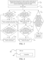
- the steps of the method for cooling a locked rotor driving motor of a vehicle are described in detail below. As shown in FIG. 3 , the method includes the following steps.
- a driving mode of the vehicle is an electric vehicle mode, and it is determined that the vehicle meets a preset locked rotor motor activation condition and a current temperature of the driving motor is greater than an auxiliary cooling starting temperature of an engine.
- Step S302 The engine of the vehicle is started.
- step S304 is performed, or else step S308 is performed.
- step S306 is performed, or else step S310 is performed.
- S306 A spill valve of the vehicle is requested to enter a forcibly closed state.
- step S308 is performed, otherwise step S304 is performed.
- step S310 is performed, otherwise step S306 is performed.
- S310 The spill valve of the vehicle is requested to be opened.
- S311 It is determined whether the vehicle meets any preset locked rotor motor exit condition and it is determined that the current temperature of the driving motor is less than an auxiliary cooling shutdown temperature of the engine.
- step S312 is performed, or else the engine is kept in a started state.
- S312 The engine is shut down after preset duration.
- the engine of the vehicle can be started when the vehicle is in the electric vehicle mode and a locked rotor occurs to the driving motor, so that the engine end oil pump of the vehicle drives the coolant in the cooling flow path to cool the driving motor, so as to solve the problem that the locked rotor of the driving motor leads to a low rotational speed of the wheel end oil pump to make it impossible to provide a sufficient coolant to cool the driving motor.
- the service life of the driving motor is reduced or the driving motor is even burnt out.
- the heat exchange with the outside is accelerated by controlling the cooling fan and the spill valve, so as to improve the cooling effect on the driving motor.
- the present disclosure further provides a device for cooling a locked rotor driving motor of a vehicle.
- the vehicle includes a driving motor, an engine, an engine end oil pump, and a cooling flow path.
- the engine is configured to drive the engine end oil pump to run, and the cooling flow path connects the engine end oil pump to the driving motor.
- the device 400 includes: a controller 401, configured to implement the steps of the method for cooling a locked rotor driving motor of a vehicle described above.
- the controller 401 is configured to: control, if a driving mode of the vehicle is an electric vehicle mode, the vehicle meets a preset locked rotor motor activation condition, and a current temperature of the driving motor is greater than an auxiliary cooling starting temperature of the engine, the engine of the vehicle to start, to cause the engine end oil pump of the vehicle to drive a coolant in the cooling flow path to cool the driving motor.
- controller 401 is further configured to:
- controller 401 is further configured to:
- the controller 401 is further configured so that if the first duration is less than or equal to first preset duration, the auxiliary cooling starting temperature of the engine is equal to a second preset temperature, where the second preset temperature is less than the first preset temperature.
- the controller 401 is further configured so that if the first duration is greater than the first preset duration, the auxiliary cooling starting temperature of the engine is equal to the first preset temperature.
- the controller 401 is further configured to: control, if the vehicle meets a preset locked rotor motor exit condition and it is determined that the current temperature of the driving motor is less than an auxiliary cooling shutdown temperature of the engine, the engine to stop running after second preset duration.
- the first preset temperature is a maximum allowable temperature of the driving motor
- the second preset temperature is a safe starting temperature of the driving motor under a locked rotor working condition
- the auxiliary cooling starting temperature of the engine is less than or equal to the first preset temperature
- controller 401 is further configured to:
- controller 401 is further configured to:
- controller 401 is configured to:
- controller 401 is further configured to:
- the preset locked rotor motor activation condition includes: a gear of the vehicle is in a forward gear or a reverse gear, a torque of the driving motor is greater than or equal to a first preset torque, and a vehicle speed of the vehicle is less than or equal to a first preset vehicle speed; and
- the vehicle includes a spill valve, and the spill valve is configured to control a flow rate in the cooling flow path.
- the controller 401 is further configured to: request, after the engine is started to cool the driving motor, if the flow rate of flowing through the cooling flow path of the driving motor is greater than a third preset cooling flow rate, the spill valve of the vehicle to enter a forcibly closed state.
- the engine of the vehicle can be started to cool the driving motor, thereby solving the problem that the locked rotor of the driving motor leads to a low rotational speed of the wheel end oil pump to make it impossible to provide a sufficient coolant to cool the driving motor. As a result, the service life of the driving motor is reduced or the driving motor is even burnt out.
- An embodiment of the present disclosure further provides a non-transitory computer-readable storage medium, having a computer program stored thereon.
- the program when executed by a processor, implements the steps of the method for cooling a locked rotor driving motor of a vehicle according to the above embodiments.
- An embodiment of the present disclosure further provides a vehicle 500, as shown in FIG. 5 , including a driving motor 501, an engine 502, an engine end oil pump 503, a cooling flow path 504, and a controller 505.
- the engine 502 is configured to drive the engine end oil pump 503 to run.
- the cooling flow path 504 connects the engine end oil pump 503 to the driving motor 501.
- the controller 505 is configured to implement the steps of the method for cooling a locked rotor driving motor of a vehicle according to the above embodiments.
- An embodiment of the present disclosure further provides a vehicle, including:
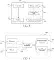
- FIG. 6 is a block diagram illustrating another vehicle 600 according to an example embodiment.
- the vehicle 600 includes one or more processors 622, and a memory 632 configured to store a computer program executable by the processor 622.
- the computer program stored in the memory 632 may include one or more modules each corresponding to a set of instructions.
- the processor 622 may be configured to execute the computer program, to perform the method for cooling a driving motor described above.
- the vehicle 600 may further include a power supply component 626 and a communication component 660.
- the power supply component 626 may be configured to perform power management of the vehicle 600.
- the communication component 660 may be configured to implement communication of the vehicle 600, such as wired or wireless communication.
- the vehicle 600 may further include an input/output (I/O) interface 668.
- the vehicle 600 may operate based on an operating system stored in the memory 632, such as Windows ServerTM, Mac OS XTM, UnixTM, and LinuxTM.
- a computer-readable storage medium including program instructions is further provided.
- the program instructions when executed by a processor, implement the steps of the method for cooling a driving motor described above.
- the non-transitory computer-readable storage medium may be the above-mentioned memory 632 including program instructions, and the above-mentioned program instructions may be executed by the processor 622 of the vehicle 600 to complete the method for cooling a driving motor described above.
- a computer program product includes a computer program executable by a programmable device.
- the computer program has a code portion for performing the method for cooling a locked rotor driving motor of a vehicle described above when executed by the programmable device.
Landscapes
- Engineering & Computer Science (AREA)
- Chemical & Material Sciences (AREA)
- Combustion & Propulsion (AREA)
- Transportation (AREA)
- Mechanical Engineering (AREA)
- Automation & Control Theory (AREA)
- Electric Propulsion And Braking For Vehicles (AREA)
- Hybrid Electric Vehicles (AREA)
- Motor Or Generator Cooling System (AREA)
- Control Of Vehicle Engines Or Engines For Specific Uses (AREA)
- Auxiliary Drives, Propulsion Controls, And Safety Devices (AREA)
Applications Claiming Priority (2)
| Application Number | Priority Date | Filing Date | Title |
|---|---|---|---|
| CN202210188260.0A CN116691328B (zh) | 2022-02-28 | 2022-02-28 | 用于车辆的驱动电机堵转冷却方法、装置及车辆 |
| PCT/CN2023/078005 WO2023160637A1 (zh) | 2022-02-28 | 2023-02-23 | 用于车辆的驱动电机堵转冷却方法、装置及车辆 |
Publications (3)
| Publication Number | Publication Date |
|---|---|
| EP4438367A1 true EP4438367A1 (de) | 2024-10-02 |
| EP4438367A4 EP4438367A4 (de) | 2025-04-09 |
| EP4438367B1 EP4438367B1 (de) | 2026-01-21 |
Family
ID=87764851
Family Applications (1)
| Application Number | Title | Priority Date | Filing Date |
|---|---|---|---|
| EP23759259.7A Active EP4438367B1 (de) | 2022-02-28 | 2023-02-23 | Verfahren und vorrichtung zur kühlung des motorantriebsstillstands für fahrzeug und fahrzeug |
Country Status (7)
| Country | Link |
|---|---|
| US (1) | US20240351574A1 (de) |
| EP (1) | EP4438367B1 (de) |
| JP (1) | JP7777231B2 (de) |
| KR (1) | KR102971494B1 (de) |
| CN (1) | CN116691328B (de) |
| ES (1) | ES3061147T3 (de) |
| WO (1) | WO2023160637A1 (de) |
Families Citing this family (4)
| Publication number | Priority date | Publication date | Assignee | Title |
|---|---|---|---|---|
| CN117389346A (zh) * | 2023-10-11 | 2024-01-12 | 中铁八局集团第一工程有限公司 | 拱座混凝土施工过程温度控制装置 |
| CN117889124A (zh) * | 2023-12-25 | 2024-04-16 | 奇瑞汽车股份有限公司 | 增程式车辆液压油路系统及汽车 |
| KR20260027699A (ko) | 2024-08-21 | 2026-03-03 | 주식회사 엘지에너지솔루션 | 파우치형 전지셀 케이스의 가공 장치 및 이를 이용한 가공방법 |
| CN119953165B (zh) * | 2025-01-17 | 2025-12-16 | 上汽通用五菱汽车股份有限公司 | 一种车辆冷却水泵的控制方法、装置、车辆及存储介质 |
Family Cites Families (14)
| Publication number | Priority date | Publication date | Assignee | Title |
|---|---|---|---|---|
| JP3876793B2 (ja) * | 2002-08-12 | 2007-02-07 | トヨタ自動車株式会社 | 多重冷却システム |
| JP4464984B2 (ja) * | 2007-04-20 | 2010-05-19 | トヨタ自動車株式会社 | 車両用オイル供給装置 |
| JP2012166737A (ja) * | 2011-02-16 | 2012-09-06 | Toyota Motor Corp | ハイブリッド車両の駆動制御装置 |
| FR2979080B1 (fr) * | 2011-08-17 | 2013-08-16 | Renault Sa | Systeme de refroidissement pour vehicule a propulsion electrique |
| JP5781919B2 (ja) * | 2011-12-28 | 2015-09-24 | トヨタ自動車株式会社 | 車両制御システム |
| JP2014000848A (ja) | 2012-06-15 | 2014-01-09 | Toyota Motor Corp | 回転電機冷却システム |
| JP5966847B2 (ja) * | 2012-10-22 | 2016-08-10 | トヨタ自動車株式会社 | 車両の制御装置 |
| CN109591602B (zh) * | 2018-12-24 | 2020-10-13 | 浙江合众新能源汽车有限公司 | 一种电动汽车的驱动电机堵转保护系统及方法 |
| JP7415370B2 (ja) * | 2019-08-21 | 2024-01-17 | マツダ株式会社 | 電気駆動車両の冷却装置 |
| CN111022142A (zh) * | 2019-12-31 | 2020-04-17 | 江门市大长江集团有限公司 | 一种混合动力总成的油冷却装置、混合动力车辆和摩托车 |
| CN111907512A (zh) * | 2020-07-29 | 2020-11-10 | 一汽解放青岛汽车有限公司 | 一种混合动力车辆冷启动控制方法及车辆 |
| CN114056109A (zh) * | 2020-07-31 | 2022-02-18 | 广州汽车集团股份有限公司 | 一种汽车低温传动效率改善方法及汽车电驱动系统 |
| CN213472768U (zh) * | 2020-09-04 | 2021-06-18 | 弗迪动力有限公司 | 动力总成和车辆 |
| CN214450260U (zh) * | 2021-03-04 | 2021-10-22 | 安徽华菱汽车有限公司 | 一种电驱动冷却系统及增程式混合动力搅拌车 |
-
2022
- 2022-02-28 CN CN202210188260.0A patent/CN116691328B/zh active Active
-
2023
- 2023-02-23 ES ES23759259T patent/ES3061147T3/es active Active
- 2023-02-23 WO PCT/CN2023/078005 patent/WO2023160637A1/zh not_active Ceased
- 2023-02-23 KR KR1020247021811A patent/KR102971494B1/ko active Active
- 2023-02-23 EP EP23759259.7A patent/EP4438367B1/de active Active
- 2023-02-23 JP JP2024539760A patent/JP7777231B2/ja active Active
-
2024
- 2024-06-28 US US18/759,757 patent/US20240351574A1/en active Pending
Also Published As
| Publication number | Publication date |
|---|---|
| CN116691328A (zh) | 2023-09-05 |
| ES3061147T3 (en) | 2026-03-31 |
| JP2024547175A (ja) | 2024-12-26 |
| WO2023160637A1 (zh) | 2023-08-31 |
| CN116691328B (zh) | 2024-08-06 |
| KR102971494B1 (ko) | 2026-06-02 |
| EP4438367A4 (de) | 2025-04-09 |
| US20240351574A1 (en) | 2024-10-24 |
| JP7777231B2 (ja) | 2025-11-27 |
| KR20240112354A (ko) | 2024-07-18 |
| EP4438367B1 (de) | 2026-01-21 |
Similar Documents
| Publication | Publication Date | Title |
|---|---|---|
| EP4438367B1 (de) | Verfahren und vorrichtung zur kühlung des motorantriebsstillstands für fahrzeug und fahrzeug | |
| CN110356210B (zh) | 车辆的温度控制装置 | |
| JP5758820B2 (ja) | 回転電機冷却システム | |
| JP2019156108A (ja) | 車両の温度制御装置 | |
| US11892072B2 (en) | Method of managing the oil temperature of a transmission of a motor vehicle | |
| KR20200014539A (ko) | 차량용 냉각 시스템의 제어방법 | |
| US11642958B2 (en) | Heat exchange system, method, non-transitory storage medium, and vehicle | |
| JP2020006742A (ja) | 車両の暖房装置 | |
| KR102030880B1 (ko) | 유체 공급장치 | |
| CN113550819B (zh) | 一种发动机暖机控制方法及装置 | |
| WO2013112468A1 (en) | Method for controlling a vehicle engine | |
| JP2002213242A (ja) | 移動体の冷却制御装置 | |
| US11028763B2 (en) | Engine cooling device | |
| JP2019014418A (ja) | 熱交換システムの制御装置 | |
| CN111900833B (zh) | 一种基于整车综合控制的动力电机热管理控制方法 | |
| JP2019127201A (ja) | 車両の冷却装置 | |
| KR20190000415A (ko) | 하이브리드 차량 제어 시스템 및 방법 | |
| JP2012021422A (ja) | 車載内燃機関の冷却装置 | |
| JP2011226423A (ja) | 車両駆動用装置冷却システム | |
| US20180135624A1 (en) | Oil supply device and method of controlling electric oil pump | |
| CN115158286B (zh) | 混合动力热管理控制系统及方法 | |
| JPH1024721A (ja) | 車両用暖房装置 | |
| JP2015068257A (ja) | エンジンの冷却装置 | |
| JP2014070592A (ja) | 制御装置 | |
| JP2014134171A (ja) | 内燃機関の冷却システムと内燃機関の冷却方法 |
Legal Events
| Date | Code | Title | Description |
|---|---|---|---|
| STAA | Information on the status of an ep patent application or granted ep patent |
Free format text: STATUS: THE INTERNATIONAL PUBLICATION HAS BEEN MADE |
|
| PUAI | Public reference made under article 153(3) epc to a published international application that has entered the european phase |
Free format text: ORIGINAL CODE: 0009012 |
|
| STAA | Information on the status of an ep patent application or granted ep patent |
Free format text: STATUS: REQUEST FOR EXAMINATION WAS MADE |
|
| 17P | Request for examination filed |
Effective date: 20240628 |
|
| AK | Designated contracting states |
Kind code of ref document: A1 Designated state(s): AL AT BE BG CH CY CZ DE DK EE ES FI FR GB GR HR HU IE IS IT LI LT LU LV MC ME MK MT NL NO PL PT RO RS SE SI SK SM TR |
|
| A4 | Supplementary search report drawn up and despatched |
Effective date: 20250310 |
|
| RIC1 | Information provided on ipc code assigned before grant |
Ipc: H02K 9/19 20060101ALI20250304BHEP Ipc: H02K 9/00 20060101ALI20250304BHEP Ipc: B60K 11/02 20060101AFI20250304BHEP |
|
| DAV | Request for validation of the european patent (deleted) | ||
| DAX | Request for extension of the european patent (deleted) | ||
| GRAP | Despatch of communication of intention to grant a patent |
Free format text: ORIGINAL CODE: EPIDOSNIGR1 |
|
| STAA | Information on the status of an ep patent application or granted ep patent |
Free format text: STATUS: GRANT OF PATENT IS INTENDED |
|
| RIC1 | Information provided on ipc code assigned before grant |
Ipc: B60K 11/02 20060101AFI20250825BHEP Ipc: H02K 9/00 20060101ALI20250825BHEP Ipc: H02K 9/19 20060101ALI20250825BHEP |
|
| INTG | Intention to grant announced |
Effective date: 20250903 |
|
| GRAS | Grant fee paid |
Free format text: ORIGINAL CODE: EPIDOSNIGR3 |
|
| P01 | Opt-out of the competence of the unified patent court (upc) registered |
Free format text: CASE NUMBER: UPC_APP_0012693_4438367/2025 Effective date: 20251110 |
|
| GRAA | (expected) grant |
Free format text: ORIGINAL CODE: 0009210 |
|
| STAA | Information on the status of an ep patent application or granted ep patent |
Free format text: STATUS: THE PATENT HAS BEEN GRANTED |
|
| AK | Designated contracting states |
Kind code of ref document: B1 Designated state(s): AL AT BE BG CH CY CZ DE DK EE ES FI FR GB GR HR HU IE IS IT LI LT LU LV MC ME MK MT NL NO PL PT RO RS SE SI SK SM TR |
|
| REG | Reference to a national code |
Ref country code: CH Ref legal event code: F10 Free format text: ST27 STATUS EVENT CODE: U-0-0-F10-F00 (AS PROVIDED BY THE NATIONAL OFFICE) Effective date: 20260121 |
|
| REG | Reference to a national code |
Ref country code: DE Ref legal event code: R096 Ref document number: 602023011089 Country of ref document: DE |
|
| REG | Reference to a national code |
Ref country code: IE Ref legal event code: FG4D |
|
| REG | Reference to a national code |
Ref country code: ES Ref legal event code: FG2A Ref document number: 3061147 Country of ref document: ES Kind code of ref document: T3 Effective date: 20260331 |
|
| PGFP | Annual fee paid to national office [announced via postgrant information from national office to epo] |
Ref country code: DE Payment date: 20260218 Year of fee payment: 4 |
|
| PGFP | Annual fee paid to national office [announced via postgrant information from national office to epo] |
Ref country code: AT Payment date: 20260301 Year of fee payment: 4 |
|
| PGFP | Annual fee paid to national office [announced via postgrant information from national office to epo] |
Ref country code: IT Payment date: 20260228 Year of fee payment: 4 |
|
| PGFP | Annual fee paid to national office [announced via postgrant information from national office to epo] |
Ref country code: FR Payment date: 20260323 Year of fee payment: 4 |
|
| REG | Reference to a national code |
Ref country code: NL Ref legal event code: MP Effective date: 20260121 |
|
| PG25 | Lapsed in a contracting state [announced via postgrant information from national office to epo] |
Ref country code: NL Free format text: LAPSE BECAUSE OF FAILURE TO SUBMIT A TRANSLATION OF THE DESCRIPTION OR TO PAY THE FEE WITHIN THE PRESCRIBED TIME-LIMIT Effective date: 20260121 |
|
| REG | Reference to a national code |
Ref country code: AT Ref legal event code: MK05 Ref document number: 1878497 Country of ref document: AT Kind code of ref document: T Effective date: 20260121 |
|
| PG25 | Lapsed in a contracting state [announced via postgrant information from national office to epo] |
Ref country code: RS Free format text: LAPSE BECAUSE OF FAILURE TO SUBMIT A TRANSLATION OF THE DESCRIPTION OR TO PAY THE FEE WITHIN THE PRESCRIBED TIME-LIMIT Effective date: 20260421 |
|
| PGFP | Annual fee paid to national office [announced via postgrant information from national office to epo] |
Ref country code: ES Payment date: 20260424 Year of fee payment: 4 |
|
| PG25 | Lapsed in a contracting state [announced via postgrant information from national office to epo] |
Ref country code: PL Free format text: LAPSE BECAUSE OF FAILURE TO SUBMIT A TRANSLATION OF THE DESCRIPTION OR TO PAY THE FEE WITHIN THE PRESCRIBED TIME-LIMIT Effective date: 20260121 |
|
| PG25 | Lapsed in a contracting state [announced via postgrant information from national office to epo] |
Ref country code: GR Free format text: LAPSE BECAUSE OF FAILURE TO SUBMIT A TRANSLATION OF THE DESCRIPTION OR TO PAY THE FEE WITHIN THE PRESCRIBED TIME-LIMIT Effective date: 20260422 |
|
| REG | Reference to a national code |
Ref country code: LT Ref legal event code: MG9D |
|
| PG25 | Lapsed in a contracting state [announced via postgrant information from national office to epo] |
Ref country code: LT Free format text: LAPSE BECAUSE OF FAILURE TO SUBMIT A TRANSLATION OF THE DESCRIPTION OR TO PAY THE FEE WITHIN THE PRESCRIBED TIME-LIMIT Effective date: 20260121 |
|
| PG25 | Lapsed in a contracting state [announced via postgrant information from national office to epo] |
Ref country code: NO Free format text: LAPSE BECAUSE OF FAILURE TO SUBMIT A TRANSLATION OF THE DESCRIPTION OR TO PAY THE FEE WITHIN THE PRESCRIBED TIME-LIMIT Effective date: 20260421 |
|
| PG25 | Lapsed in a contracting state [announced via postgrant information from national office to epo] |
Ref country code: FI Free format text: LAPSE BECAUSE OF FAILURE TO SUBMIT A TRANSLATION OF THE DESCRIPTION OR TO PAY THE FEE WITHIN THE PRESCRIBED TIME-LIMIT Effective date: 20260121 Ref country code: SE Free format text: LAPSE BECAUSE OF FAILURE TO SUBMIT A TRANSLATION OF THE DESCRIPTION OR TO PAY THE FEE WITHIN THE PRESCRIBED TIME-LIMIT Effective date: 20260121 Ref country code: AT Free format text: LAPSE BECAUSE OF FAILURE TO SUBMIT A TRANSLATION OF THE DESCRIPTION OR TO PAY THE FEE WITHIN THE PRESCRIBED TIME-LIMIT Effective date: 20260121 |
|
| PG25 | Lapsed in a contracting state [announced via postgrant information from national office to epo] |
Ref country code: HR Free format text: LAPSE BECAUSE OF FAILURE TO SUBMIT A TRANSLATION OF THE DESCRIPTION OR TO PAY THE FEE WITHIN THE PRESCRIBED TIME-LIMIT Effective date: 20260121 |
|
| PG25 | Lapsed in a contracting state [announced via postgrant information from national office to epo] |
Ref country code: IS Free format text: LAPSE BECAUSE OF FAILURE TO SUBMIT A TRANSLATION OF THE DESCRIPTION OR TO PAY THE FEE WITHIN THE PRESCRIBED TIME-LIMIT Effective date: 20260521 Ref country code: PT Free format text: LAPSE BECAUSE OF FAILURE TO SUBMIT A TRANSLATION OF THE DESCRIPTION OR TO PAY THE FEE WITHIN THE PRESCRIBED TIME-LIMIT Effective date: 20260521 |
|
| PG25 | Lapsed in a contracting state [announced via postgrant information from national office to epo] |
Ref country code: LV Free format text: LAPSE BECAUSE OF FAILURE TO SUBMIT A TRANSLATION OF THE DESCRIPTION OR TO PAY THE FEE WITHIN THE PRESCRIBED TIME-LIMIT Effective date: 20260121 |
|
| PG25 | Lapsed in a contracting state [announced via postgrant information from national office to epo] |
Ref country code: BG Free format text: LAPSE BECAUSE OF FAILURE TO SUBMIT A TRANSLATION OF THE DESCRIPTION OR TO PAY THE FEE WITHIN THE PRESCRIBED TIME-LIMIT Effective date: 20260121 |