EP4438996A1 - Système de protection contre le retournement et véhicule protégé - Google Patents
Système de protection contre le retournement et véhicule protégé Download PDFInfo
- Publication number
- EP4438996A1 EP4438996A1 EP24162725.6A EP24162725A EP4438996A1 EP 4438996 A1 EP4438996 A1 EP 4438996A1 EP 24162725 A EP24162725 A EP 24162725A EP 4438996 A1 EP4438996 A1 EP 4438996A1
- Authority
- EP
- European Patent Office
- Prior art keywords
- vehicle
- protection system
- rollover protection
- protective element
- protected vehicle
- Prior art date
- Legal status (The legal status is an assumption and is not a legal conclusion. Google has not performed a legal analysis and makes no representation as to the accuracy of the status listed.)
- Pending
Links
- 230000001681 protective effect Effects 0.000 claims abstract description 162
- 230000001105 regulatory effect Effects 0.000 claims description 5
- 238000005096 rolling process Methods 0.000 description 11
- 230000008878 coupling Effects 0.000 description 9
- 238000010168 coupling process Methods 0.000 description 9
- 238000005859 coupling reaction Methods 0.000 description 9
- 230000006378 damage Effects 0.000 description 7
- 208000027418 Wounds and injury Diseases 0.000 description 6
- 208000014674 injury Diseases 0.000 description 6
- 239000000725 suspension Substances 0.000 description 6
- 230000001960 triggered effect Effects 0.000 description 6
- 239000002360 explosive Substances 0.000 description 5
- 230000000712 assembly Effects 0.000 description 3
- 238000000429 assembly Methods 0.000 description 3
- 230000009977 dual effect Effects 0.000 description 3
- 230000005484 gravity Effects 0.000 description 3
- 241000272525 Anas platyrhynchos Species 0.000 description 2
- 241001415801 Sulidae Species 0.000 description 2
- 230000001133 acceleration Effects 0.000 description 2
- 238000001514 detection method Methods 0.000 description 2
- 238000011084 recovery Methods 0.000 description 2
- 230000002441 reversible effect Effects 0.000 description 2
- 229910000831 Steel Inorganic materials 0.000 description 1
- 230000004913 activation Effects 0.000 description 1
- 238000007792 addition Methods 0.000 description 1
- 229910052782 aluminium Inorganic materials 0.000 description 1
- XAGFODPZIPBFFR-UHFFFAOYSA-N aluminium Chemical compound [Al] XAGFODPZIPBFFR-UHFFFAOYSA-N 0.000 description 1
- 239000000969 carrier Substances 0.000 description 1
- 238000006243 chemical reaction Methods 0.000 description 1
- 238000010276 construction Methods 0.000 description 1
- 238000005516 engineering process Methods 0.000 description 1
- 239000012530 fluid Substances 0.000 description 1
- 230000002427 irreversible effect Effects 0.000 description 1
- 238000005184 irreversible process Methods 0.000 description 1
- 229910052751 metal Inorganic materials 0.000 description 1
- 239000002184 metal Substances 0.000 description 1
- 239000010959 steel Substances 0.000 description 1
- 239000000126 substance Substances 0.000 description 1
Images



Classifications
-
- F—MECHANICAL ENGINEERING; LIGHTING; HEATING; WEAPONS; BLASTING
- F41—WEAPONS
- F41H—ARMOUR; ARMOURED TURRETS; ARMOURED OR ARMED VEHICLES; MEANS OF ATTACK OR DEFENCE, e.g. CAMOUFLAGE, IN GENERAL
- F41H7/00—Armoured or armed vehicles
- F41H7/02—Land vehicles with enclosing armour, e.g. tanks
-
- B—PERFORMING OPERATIONS; TRANSPORTING
- B60—VEHICLES IN GENERAL
- B60R—VEHICLES, VEHICLE FITTINGS, OR VEHICLE PARTS, NOT OTHERWISE PROVIDED FOR
- B60R21/00—Arrangements or fittings on vehicles for protecting or preventing injuries to occupants or pedestrians in case of accidents or other traffic risks
- B60R21/02—Occupant safety arrangements or fittings, e.g. crash pads
- B60R21/13—Roll-over protection
-
- F—MECHANICAL ENGINEERING; LIGHTING; HEATING; WEAPONS; BLASTING
- F41—WEAPONS
- F41H—ARMOUR; ARMOURED TURRETS; ARMOURED OR ARMED VEHICLES; MEANS OF ATTACK OR DEFENCE, e.g. CAMOUFLAGE, IN GENERAL
- F41H5/00—Armour; Armour plates
- F41H5/22—Manhole covers, e.g. on tanks; Doors on armoured vehicles or structures
- F41H5/223—Manhole covers specially adapted for armoured or fighting vehicles
-
- B—PERFORMING OPERATIONS; TRANSPORTING
- B60—VEHICLES IN GENERAL
- B60R—VEHICLES, VEHICLE FITTINGS, OR VEHICLE PARTS, NOT OTHERWISE PROVIDED FOR
- B60R21/00—Arrangements or fittings on vehicles for protecting or preventing injuries to occupants or pedestrians in case of accidents or other traffic risks
- B60R21/02—Occupant safety arrangements or fittings, e.g. crash pads
- B60R21/13—Roll-over protection
- B60R2021/132—Roll bars for convertible vehicles
- B60R2021/134—Roll bars for convertible vehicles movable from a retracted to a protection position
- B60R2021/135—Roll bars for convertible vehicles movable from a retracted to a protection position automatically during an accident
Definitions
- the present invention relates to a rollover protection system for a protected vehicle and a protected vehicle with such a rollover protection system.
- an object of the present invention is to provide an improved rollover protection system for a protected vehicle.
- the rollover protection system comprises a protective element for protecting a crew member who is partly inside and partly outside the protected vehicle in the event of a rollover of the protected vehicle and an actuator assigned to the protective element, wherein the actuator is designed to move the protective element from a retracted state to an extended state immediately before or during the rollover of the protected vehicle, and wherein the protective element in the extended state protrudes beyond areas of the crew member which are arranged outside the protected vehicle during the rollover.
- the protective element in the extended state extends beyond the crew member's areas that are located outside the protected vehicle during a rollover of the protected vehicle, the protected vehicle supports itself on the protective element in the event of a rollover, giving the crew member time to retreat completely into the protected vehicle. This significantly reduces the risk of the crew member being injured by the overturning protected vehicle.
- a "rollover protection system” is not to be understood as a system that prevents the protected vehicle from rolling over or overturning, but rather as a system that prevents or at least reduces the possible negative consequences of the protected vehicle rolling over for the crew member.
- the rollover protection system can also be referred to as a rollover protection device.
- the rollover protection system can preferably be retrofitted to protected vehicles that do not yet have such a rollover protection system from the factory. The rollover protection system can therefore be retrofitted.
- the rollover protection system is preferably modular in design. This means in particular that the rollover protection system can be attached to the protected vehicle as a retrofit module. Alternatively, the protected vehicle can also be equipped with such a rollover protection system from the factory.
- the fact that the vehicle is "protected” means in particular that the protected vehicle is protected against gunfire, booby traps, improvised explosive devices (IEDs), mines or the like.
- the protected vehicle can be armored.
- the protected vehicle can be a tracked vehicle or a wheeled vehicle. It is assumed below that the protected vehicle is a wheeled vehicle.
- the protected vehicle can have several wheel axles on which wheels are provided. For example, four wheel axles with eight wheels are provided. However, fewer or more than four wheel axles can also be provided.
- the protected vehicle preferably has a protected vehicle cell.
- the protected vehicle cell can in particular be an exchangeable mission module of the protected vehicle.
- An example of such a mission module is a medical module.
- the protected vehicle, in particular the protected vehicle cell has, for example, an inclined front wall and a roof.
- the rollover protection system can prevent the protected vehicle from coming to rest on the front wall or on the roof, in particular if the protected vehicle rolls over.
- One or more hatch openings can be provided on the protected vehicle or on the protected vehicle cell.
- Each hatch opening can be assigned such a rollover protection system.
- each hatch opening can be opened and closed with the aid of a movable, in particular sliding or pivoting, hatch cover.
- the hatch opening or hatch openings can be provided on a wall of the protected vehicle or the protected vehicle cell.
- the wall can be part of the aforementioned roof or the aforementioned front wall.
- the fact that the crew member is or is located "partly inside and partly outside” the protected vehicle can mean in this case that the crew member, for example, stretches his upper body, in particular at least his head, out of a hatch opening as mentioned above in order to drive over the hatch.
- the lower body of the crew member can be in an interior of the protected vehicle or the protected vehicle cell, with the upper body outside this interior in an environment of the protected vehicle.
- "Partly inside and partly outside” is to be understood in this case in particular to mean that the crew member is simultaneously partly inside and partly outside the interior.
- the protected vehicle is preferably assigned a coordinate system with a first spatial direction, longitudinal direction or x-direction, a second spatial direction, vertical direction or y-direction and a third spatial direction, transverse direction or z-direction.
- the directions are oriented perpendicular to one another.
- a movement of the protected vehicle in the x-direction can be referred to as rolling or rolling movement.
- a movement of the protected vehicle in the y-direction can be referred to as yawing or yaw movement.
- a movement of the protected vehicle in the z-direction can be referred to as pitching or pitching movement.
- a direction of travel of the protected vehicle is preferably oriented against the x-direction. However, the protected vehicle can also move against the direction of travel - for example when reversing.
- a “rollover” of the protected vehicle is to be understood in particular as meaning that the protected vehicle turns at least from the wheels onto the roof or the front wall.
- the protected vehicle may turn at least once or several times around the x-direction, which is preferably oriented perpendicular to the wheel axes, during the rollover. and/or rolls over or rotates around the z-direction, which is preferably oriented parallel to the wheel axes.
- a rollover of the protected vehicle can also be a combined rolling, yawing and/or pitching movement.
- "Immediately before the rollover” can mean in this case that the protective element is triggered fractions of a second before the actual rollover. This can be done based on sensor signals from a sensor system of the rollover protection system.
- the fact that the protective element "protects" the crew member means in particular that the protective element prevents the crew member from becoming trapped between the protected vehicle and the ground on which the protected vehicle is moving.
- the crew member gains enough time to be able to retreat into the interior before the crew member comes into contact with the ground or with objects arranged in the vicinity of the protected vehicle.
- the actuator can also be referred to as an actuator or as an actuating element.
- actuators can be assigned to the protective element. However, only one actuator will be discussed below.
- the actuator can, for example, explosively release a fluid, in particular a gas.
- the actuator is suitable for converting energy in order to move the protective element from the retracted state to the extended state.
- the actuator can convert chemical energy into mechanical energy.
- the actuator can be a gas generator, in particular a pyrotechnic one. However, this is not absolutely necessary.
- the protective element in the extended state "protrudes" beyond areas of the crew member which are located outside the protected vehicle during a rollover means in particular to be understood that the protective element projects or protrudes so far beyond the areas of the crew member, for example the crew member's head, which protrude from the hatch opening that, in the event of the protected vehicle overturning, the crew member does not come into contact with the ground, but the protective element contacts the ground.
- the rollover protection system comprises a hatch cover for opening and closing a hatch opening provided on the protected vehicle, wherein the protective element is decoupled from the hatch cover.
- the hatch opening is preferably provided on the previously mentioned wall of the protected vehicle or the protected vehicle cell.
- the wall can be part of the roof or the front wall of the protected vehicle.
- the hatch cover can be pivotably attached to the wall. In this case, the hatch cover can be pivoted to open and close the hatch opening. However, the hatch cover can also be linearly displaced to open and close the hatch opening.
- the fact that the protective element is "decoupled" from the hatch cover means in particular that no functional operative connection is provided between the hatch cover and the protective element.
- the hatch cover is neither mechanically operatively connected to the protective element, nor is there an operative connection of any kind such that the hatch cover cannot be opened and closed depending on the state of the protective element.
- the protective element performs a linear and/or a rotational movement when it is moved from the retracted state to the extended state.
- the protective element moves along the y-direction when it is moved from the retracted state to the extended state.
- the protective element can also perform a rotary movement instead of a linear movement when it is moved from the retracted state to the extended state.
- the protective element can be pivoted about an axis of rotation in such a way that the protective element performs a pivoting movement or rotary movement about this axis of rotation in order to move the protective element from the retracted state to the extended state and optionally also vice versa.
- a combination of a linear and a rotary movement can also be provided in order to move the protective element from the retracted state to the extended state and optionally vice versa.
- the protective element locks in the extended state.
- a mechanical locking device can be provided for this purpose.
- the locking device can be or have a pawl, for example, which engages positively in the protective element in the extended state.
- the fact that the protective element locks in the extended state prevents, for example, the protective element from being moved from the extended state back to the retracted state by the weight of the protected vehicle acting on it. This in particular prevents the actuator from being loaded with the entire weight of the protected vehicle.
- the protective element has a protective bracket which is guided linearly on guide sleeves by means of guide elements, wherein the guide elements are connected to the protective bracket.
- the guide elements are preferably arranged at a distance from one another and are firmly connected to the protective bar, for example screwed or welded to it.
- Each guide element is in particular assigned a guide sleeve of this type.
- the guide sleeves can be firmly connected, in particular welded, to a supporting structure of the protected vehicle or the protected vehicle cell.
- the supporting structure can be, for example, the previously mentioned wall.
- the actuator or actuators can be integrated into the guide sleeves. However, this is not absolutely necessary.
- the actuator is coupled to the protective bar.
- a coupling element can be provided to couple the actuator to the protective bar.
- the coupling element can be rod-shaped.
- the coupling element is a piston of a hydraulic cylinder.
- the actuator itself can be a hydraulic cylinder, with the coupling element being part of the actuator.
- the coupling element can be operatively connected or coupled to the protective bar, for example with the aid of a ball head.
- the coupling element can also be screwed or welded to the protective bar.
- the protective bar has a central section and side sections attached to the ends of the central section, wherein the side sections are oriented obliquely to the central section.
- the protective bar therefore preferably has an arcuate geometry.
- the middle section is arranged between a first side section and a second side section.
- the protective bar in particular the side sections of the protective bar, rests on the wall of the protected vehicle or the protected vehicle cell.
- the protective bar can rest on an outer side of the wall.
- a pocket or recess can also be provided in the wall, in which the protective bar is accommodated in the retracted state. In this case, the protective bar does not protrude beyond the outer side of the wall in the retracted state, but is arranged flush with it or stands behind it.
- the protective element is stamp-shaped.
- the protective element can have a circular cross-section, for example.
- the protective element is in particular accommodated in a guide element and guided linearly on it.
- the guide element can be connected to the previously mentioned supporting structure of the protected vehicle or the protected vehicle cell.
- the guide sleeve is screwed or welded to the wall.
- the protective element can in particular be a piston of a hydraulic cylinder.
- the guide sleeve is a housing of the hydraulic cylinder, and the actuator can be integrated into the guide sleeve.
- a different structure is also possible.
- the actuator is configured to move the protective element from the extended state back to the retracted state.
- the protected vehicle can also be turned at least from the roof or the front wall to one side of the protected vehicle by means of a suitable control of the protective element using the actuator.
- the actuator is designed to move the protective element pneumatically, hydraulically, electrically, mechanically and/or explosively from the retracted state to the extended state.
- the actuator can function purely mechanically.
- the actuator can have pre-tensioned spring assemblies, for example.
- the actuator can be a hydraulic cylinder or have a hydraulic cylinder.
- the hydraulic cylinder can be simple or telescopic.
- An electrical operating principle is also possible.
- the actuator can comprise an electric motor with an adjustment device, for example.
- the actuator can also function explosively.
- a gas generator in particular a pyrotechnic one, can be used as the actuator. Combinations of the aforementioned operating principles can also be used. Electromechanical operating principles are particularly possible here.
- the rollover protection system has a sensor system which is designed to detect a tilting of the protected vehicle about at least one spatial direction, and a regulating and control unit which is designed to control the actuator based on sensor signals of the sensor system such that the actuator moves the protective element from the retracted state to the extended state immediately before or during the rollover of the protected vehicle.
- the sensor system can include a wide variety of sensors.
- the sensor system can have one or more inclination sensors, one or more position sensors, one or more acceleration sensors or the like.
- the sensor system is operatively connected to the control unit of the rollover protection system.
- the operative connection can be wired or wireless.
- the control unit can be an internal vehicle system, such as a CAN node (Controller Area Network), or any control device.
- the control unit is in turn operatively connected to the actuator.
- the operative connection can be wired or wireless.
- the control unit is used to evaluate data and to transmit control signals to the actuator.
- a tilting of the protected vehicle in the x-direction, the y-direction and/or the z-direction can be detected. If a certain preset limit value for the tipping of the protected vehicle is exceeded, so that there is a certain probability that the protected vehicle will roll over, the control unit controls the actuator in such a way that it moves the protective element from the retracted state to the extended state.
- the sensors for rollover detection can also be used for other components of the protected vehicle that require specific position information about the protected vehicle. This applies, for example, to a weapon sensor for an armament of the protected vehicle.
- the rollover protection system has a support element for supporting the crew member and an adjustment unit for adjusting a height position of the support element, wherein the regulating and control unit is designed to control the adjustment unit based on sensor signals from the sensor system in such a way that the adjustment unit adjusts the height position of the support element immediately before or during the rollover of the protected vehicle. adjusted in such a way that the crew member moves completely into the protected vehicle.
- the time gained by the protective element can therefore be used to move the crew member completely into the protected vehicle with the aid of the support element and the adjustment unit.
- the adjustment unit is suspended from the protected vehicle cell, in particular from the wall, with the aid of a suspension.
- the support element is preferably arranged within the interior. With the aid of the adjustment unit, a position of the support element can be adjusted along the y-direction or along the vertical direction of the protected vehicle. In this case, the "height position" is to be understood as the position of the support element along the y-direction or along the vertical direction.
- the support element and the protective element preferably move in different, in particular opposite, directions.
- the support element moves against the y-direction, in particular downwards, while the protective element moves along the y-direction, in particular upwards.
- the protective bar and the support element move away from each other when the protective element is moved from the retracted state to the extended state. This means in particular that the protective bar and the support element move in opposite directions when the rollover protection system is triggered.
- the support element can be a seat for the crew member. Accordingly, the terms "support element” and "seat” can be interchanged as desired. Alternatively, the support element can also be a standing platform for the crew member.
- the crew member can be strapped to such a standing platform so that the crew member cannot be thrown out of the protected vehicle cell if the protected vehicle rolls over.
- the rollover protection system includes a support element in the form of a seat.
- the crew member can be strapped to or on the support element in the form of a seat, so that in this case too the crew member cannot be thrown out of the protected vehicle cell if the protected vehicle rolls over.
- the adjustment unit can accordingly be referred to as a seat adjustment unit. Accordingly, the terms "adjustment unit” and "seat adjustment unit” are interchangeable in this case.
- the protected vehicle can have several such rollover protection systems.
- the protected vehicle can have several hatch openings, whereby each hatch opening can be assigned a rollover protection system of this kind.
- each hatch opening does not necessarily have to be assigned a rollover protection system of this kind.
- the protected vehicle is in particular a military vehicle.
- the protected vehicle can therefore also be referred to as a military vehicle.
- the protected vehicle is an armored transport vehicle.
- the protected vehicle can also be, for example, an infantry fighting vehicle, a battle tank, an armored recovery vehicle, a mine-clearing vehicle, an armored reconnaissance vehicle or the like.
- the protected vehicle can in particular also be a wheeled armored vehicle.
- the protected vehicle can be referred to as a protected military vehicle.
- the protected vehicle comprises the protected vehicle cell.
- the protected vehicle cell is preferably designed in the manner of an exchangeable mission module.
- the protected vehicle comprises a rollover protection system with a protective element for protecting a crew member who is partly inside and partly outside the protected vehicle in the event of a rollover of the protected vehicle and an actuator associated with the protective element, wherein the actuator is configured to move the protective element from a retracted state to an extended state immediately or in the event of a rollover of the protected vehicle, and wherein the protective element in the extended state protrudes beyond areas of the crew member which are arranged outside the protected vehicle during the rollover.
- the protected vehicle cell comprises a rollover protection system with a protective element for protecting a crew member who is partially inside and partially outside the protected vehicle cell in the event of a rollover of the protected vehicle cell and an actuator assigned to the protective element, wherein the actuator is designed to move the protective element from a retracted state to an extended state immediately before or during the rollover of the protected vehicle cell, and wherein the protective element in the extended state protrudes beyond areas of the crew member that are arranged outside the protected vehicle cell during the rollover.
- the protected vehicle has a wall with a hatch opening, wherein the rollover protection system is mounted on the wall.
- the wall can be part of the roof or the front wall of the protected vehicle or the protected vehicle cell.
- Several hatch openings can be provided on the wall.
- Each hatch opening can be assigned a hatch cover.
- each hatch opening can also be assigned a rollover protection system as previously explained.
- a rollover protection system is assigned to a hatch opening, the The hatch cover associated with the respective hatch opening is decoupled from the protective element of the rollover protection system. This means in particular that preferably neither a mechanical nor a functional connection is provided between the protective element and the hatch cover.
- the rollover protection system comprises a guide sleeve for linearly guiding the protective element, wherein the guide sleeve is connected to the protected vehicle.
- the rollover protection system has a protective bar as mentioned above, two guide elements are assigned to it, for example, with each guide element being assigned a guide sleeve.
- the guide sleeves can be connected, in particular welded, to a supporting structure of the protected vehicle or the protected vehicle cell as mentioned above.
- the supporting structure can be the wall mentioned above.
- the protective element is stamp-shaped, it is preferably assigned exactly one guide sleeve. This guide sleeve can in particular be firmly connected to the wall.
- rollover protection system and/or the protected vehicle also include combinations of features or embodiments described above or below with regard to the exemplary embodiments that are not explicitly mentioned.
- the person skilled in the art will also add individual aspects as improvements or additions to the respective basic form of the rollover protection system and/or the protected vehicle.
- the Fig. 1 shows a schematic side view of an embodiment of a protected vehicle 1.
- the protected vehicle 1 is referred to below simply as a vehicle.
- the vehicle 1 can be a military vehicle, in particular a military utility vehicle.
- the vehicle 1 can therefore also be referred to as a military vehicle or as a military utility vehicle.
- the vehicle 1 is an armored transport vehicle.
- the vehicle 1 can also be, for example, an infantry fighting vehicle, a battle tank, an armored recovery vehicle, an armored mine clearing vehicle, an armored reconnaissance vehicle or the like.
- the vehicle 1 can also be a wheeled armored vehicle.
- the vehicle 1 comprises a protected vehicle cell 2.
- the protected vehicle cell 2 is referred to simply as the vehicle cell.
- the vehicle cell 2 can be a vehicle hull and can therefore also be referred to as such.
- the terms "vehicle cell” and “vehicle hull” can therefore be used interchangeably.
- the vehicle 1 can be armed or unarmed.
- the vehicle 1 can have a vehicle weight of more than 20 tons.
- the vehicle cell 2 is armoured.
- the vehicle cell 2 is particularly protected against gunfire, booby traps, improvised explosive devices or incendiary devices (USBV, English: Improvised Explosive Devices, IED), mines or the like.
- the vehicle cell 2 encloses a vehicle interior or interior space 3 in which a crew of the vehicle 1 can be located.
- the interior space 3 is accessible from an environment 4 of the vehicle 1 via doors and/or hatches (not shown).
- the interior space 3 can be divided into several sections or rooms that can be separated from one another.
- the interior space 3 can be divided into an engine room, a crew room and/or a driver's room. However, this is not absolutely necessary.
- the vehicle cell 2 can also be replaced at least partially or completely in a modular manner.
- the vehicle 1 can have different mission modules, mission kits or equipment sets that can be replaced as desired.
- An example of such a mission module is a medical module.
- this modular structure explained above is arbitrary.
- the vehicle cell 2 comprises, for example, a roof 5 and a front wall 6 arranged at an angle to the roof 5.
- the vehicle 1 can be a wheeled vehicle or a tracked vehicle. However, it is assumed below that the vehicle 1 is a wheeled vehicle.
- the vehicle 1 comprises several wheel axles 7, 8, 9, 10 on which wheels 11, 12, 13, 14 are provided. For example, four wheel axles 7, 8, 9, 10 with eight wheels 11, 12, 13, 14 are provided. However, fewer or more than four wheel axles 7, 8, 9, 10 can also be provided.
- a "wheel axle” is understood here to mean an axle around which the respective wheel 11, 12, 13, 14 rotates.
- the number of wheel axles 7, 8, 9, 10 is basically arbitrary. For example, four wheel axles 7, 8, 9, 10 or three wheel axles 7, 8, 9, 10 can be provided.
- Each wheel axle 7, 8, 9, 10 is assigned two wheels 11, 12, 13, 14. At least the wheels 11, 12 are steerable. Preferably, however, all wheels 11, 12, 13, 14 steerable.
- the vehicle 1 comprises an all-wheel drive. This means that all wheel axles 7, 8, 9, 10 are driven.
- the vehicle 1 can have a turret 15 with an armament 16.
- the turret 15 is rotatably mounted on the vehicle cell 2.
- the turret 15 can comprise an electric or hydraulic drive unit to rotate the turret 15 about a rotation axis 17 relative to the vehicle cell 2.
- the turret 15 can also be operated manually if the drive unit fails.
- the armament 16 can be a machine gun or the like.
- the armament 16 can be a primary armament or main armament.
- a secondary armament for example in the form of a machine gun, can be provided.
- the vehicle 1 is assigned a coordinate system with a first spatial direction, longitudinal direction or x-direction x, a second spatial direction, vertical direction or y-direction y and a third spatial direction, transverse direction or z-direction z.
- the directions x, y, z are oriented perpendicular to one another.
- a movement of the vehicle 1 around the x-direction x can be referred to as a rolling or rolling movement.
- a movement of the vehicle 1 around the y-direction y can be referred to as a yawing or yaw movement.
- a movement of the vehicle 1 around the z-direction z can be referred to as a pitching or pitching movement.
- a direction of gravity g can be oriented essentially opposite to the y-direction y.
- a weight force G of the vehicle 1 acts along the direction of gravity g.
- the vehicle 1 can move along a direction of travel F and opposite to the direction of travel F on a floor or surface 18.
- the direction of travel F can be oriented opposite to the x-direction x.
- the surface 18 can be a roadway or any terrain.
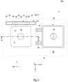
- the Fig. 2 shows a schematic plan view of an embodiment of a rollover protection system 19A for the vehicle 1.
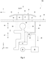
- the Fig. 3 shows a schematic sectional view of the rollover protection system 19A.
- the Fig. 4 shows another schematic sectional view of the rollover protection system 19A. The following is the Fig. 2 to 4 simultaneously referred to.
- a hatch opening 21 is provided on a wall 20 of the vehicle cell 2, in particular on the roof 5 or on the front wall 6, through which the interior 3 can be left into the surroundings 4 or the interior 3 can be entered from the surroundings 4.
- the wall 20 can be part of the roof 5 or the front wall 6, for example.
- the wall 20 can run horizontally. However, the wall 20 can also be arranged diagonally or vertically.
- the vehicle 1 can have any number of hatch openings 21.
- a hatch opening 21 can also be provided on the tower 15.
- the wall 20 can also be part of the tower 15.
- the hatch opening 21 can have any geometry.
- the hatch opening 21 can be rectangular or round. Viewed along the z-direction z, the hatch opening 21 can be placed to the left or right of the tower 15.
- the hatch opening 21 is assigned a hatch cover 22, with the help of which the hatch opening 21 can be closed.
- the hatch cover 22 is in the Fig. 3 and 4 not shown.
- the hatch cover 22 can be a hinged hatch cover, a sliding hatch cover, a lifting hatch cover or a cover with a combined translatory and rotary opening and closing movement. It is assumed below that the hatch cover 22 is a hinged hatch cover. This means that the hatch cover 22 is mounted on the wall 20 so as to be rotatable about an axis of rotation 23. The axis of rotation 23 can run parallel to the z-direction z.
- the hatch cover 22 can be moved from a closed position (not shown) to a position shown in the Fig. 2 shown open position.
- the hatch cover 22 can be locked in its open position so that the hatch cover 22 cannot close automatically even if the vehicle 1 rolls over.
- the hatch cover 22 is attached to the wall 20 by means of hinges 24, 25. In the open position, the hatch cover 22 can rest on the wall 20. However, this is not absolutely necessary. In the open position, the hatch cover 22 can also not rest on the wall 20.
- the hatch cover 22 can have a locking unit 26 for locking and unlocking the hatch cover 22.
- the wall 20 has an outer side 27 facing the environment 4. An inner side 28 of the wall 20 facing away from the outer side 27 faces the interior 3.
- each hatch opening 21 of the vehicle 1 can be assigned such a rollover protection system 19A.
- Each hatch opening 21 can be provided with exactly one rollover protection system 19A.
- exactly one rollover protection system 19A is shown. This rollover protection system 19A is placed to the right of the hatch opening 21 when viewed along the direction of travel F.
- the rollover protection system 19A can also be placed to the left of the hatch opening 21 when viewed along the direction of travel F. Such a rollover protection system 19A can also be placed to the left and right of the hatch opening 21 when viewed along the direction of travel F.
- the rollover protection system 19A is particularly suitable for vehicle weights of more than 20 tons.
- the rollover protection system 19A comprises a protective element 30 which can be extended along the y-direction y.
- the rollover protection system 19A or the protective element 30 can be extended by a Fig. 2 and 3 shown retracted state Z1 into a position shown in the Fig. 4 shown extended state Z2 and vice versa.
- the protective element 30 comprises a protective bar 31.
- the protective bar 31 can be cage-shaped and extend over the hatch opening 21 as viewed along the x-direction x and the z-direction z and thus cover it. In this case, however, the protective element 30 is nevertheless designed such that the hatch cover 22 can be opened and closed both in the retracted state Z1 and in the extended state Z2.
- the protective bar 31 is in the present case bow-shaped and can have a horizontally extending central section 32 and two side sections 33, 34 attached to the side of the central section 32 and extending obliquely thereto, which in the orientation of the Fig. 3 and 4 are oriented diagonally downwards.
- the side sections 33, 34 are optional.
- the protective bar 31 can also have only the middle section 32. In this case, the side sections 33, 34 are omitted.
- the protective bar 31 can be made of a metal tube, in particular from a steel tube or from an aluminum tube. In this case, the side sections 33, 34 can be bent with respect to the central section 32.
- the protective bar 31 can also be a welded construction.
- the protective bar 31 can rest on or abut against the outer side 27 of the wall 20, at least in sections.
- a pocket or recess 35 can be provided on the wall 20, in which the protective bar 31 is completely accommodated in the retracted state Z1, so that the protective bar 31 does not protrude beyond the outer side 27.
- the protective bar 31 can be arranged flush with the outer side 27 or can be set back behind it.
- the recess 35 is, however, optional. In the event that no such recess 35 is provided, the protective bracket 31 can rest with its obliquely oriented side sections 33, 34 on the outer side 27 of the wall 20, as shown in the Fig. 3 shown.
- the protective element 30 comprises, in addition to the protective bar 31, two guide elements 36, 37.
- a first guide element 36 and a second guide element 37 are provided.
- the guide elements 36, 37 can be rod-shaped.
- the guide elements 36, 37 are firmly connected to the protective bar 31, in particular welded or screwed to it.
- the guide elements 36, 37 can be circular in cross-section.
- Each guide element 36, 37 is assigned a guide sleeve 38, 39.
- One of the guide elements 36, 37 is accommodated in each guide sleeve 38, 39.
- the guide sleeves 38, 39 are firmly connected to a supporting structure of the vehicle cell 2 or the vehicle 1.
- the guide sleeves 38, 39 are connected to the wall 20 welded.
- a first guide sleeve 38 and a second guide sleeve 39 are provided.
- the guide elements 36, 37 can be moved out of the guide sleeves 38, 39 and back into them in order to move the protective element 30 from the retracted state Z1 to the extended state Z2 and vice versa, as shown in the Fig. 3 and 4 is indicated by a double arrow 40.
- the protective element 30 is thus telescopic.
- Telescopic in this context means in particular that the protective element 30 can be extended and thus moved from the retracted state Z1 to the extended state Z2.
- the protective element 30 can also be retracted again and thus moved from the extended state Z2 to the retracted state Z1.
- the rollover protection system 19A has an actuator 41 which is coupled to the protective bar 31 by means of a coupling element 42.
- the actuator 41 can also be referred to as an actuator or as a control element. Furthermore, such an actuator 41 can also be integrated into each of the guide sleeves 38, 39.
- the actuator 41 is suitable for moving the protective element 30 from the retracted state Z1 to the extended state Z2 within a few hundredths of a second.
- the actuator 41 can also be suitable for moving the protective element 30 from the extended state Z2 back to the retracted state Z1. However, this is not absolutely necessary.
- the actuator 41 is a hydraulic cylinder or a pneumatic cylinder.
- the coupling element 42 can be a piston of the hydraulic cylinder or the pneumatic cylinder.
- the actuator 41 can also be an electric motor, in particular a linear motor, or have an electric motor.
- the actuator 41 can also be a gas generator, in particular a pyrotechnic gas generator. In this case, the actuator 41 is only suitable for a one-time movement of the protective element 30 from the retracted state Z 1 to the extended state Z2.
- the rollover protection system 19A further comprises a sensor system 43.
- the sensor system 43 can comprise a wide variety of sensors.
- the sensor system 43 can have one or more inclination sensors, one or more position sensors, one or more acceleration sensors or the like.
- the sensor system 43 is operatively connected to a control unit 44 of the rollover protection system 19A.
- the operative connection can be wired or wireless.
- the control unit 44 can be an internal vehicle system, such as a CAN node (Controller Area Network), or any control device.
- the control unit 44 is in turn operatively connected to the actuator 41.
- the operative connection can be wired or wireless.
- the control unit 44 is used to evaluate data and to forward control signals to the actuator 41.
- a movement or tilting of the vehicle 1 around the x-direction x, around the y-direction y and/or around the z-direction z can be detected.
- the movement or tilting of the vehicle 1 can be a combined rolling, yawing and/or pitching movement. If a certain preset limit value of the tilting is exceeded so that it is expected that the vehicle 1 will roll over, the control unit 44 controls the actuator 41 in such a way that it switches the protective element 30 from the retracted state Z1 ( Fig. 2 and 3 ) to the extended state Z2 ( Fig. 4 ).
- the protective element 30 can be moved from the retracted state Z1 to the extended state Z2 within fractions of a second, for example within approximately 20 to 50 milliseconds.
- the sensor system 43 can also comprise one or more sensors that are suitable for detecting whether the hatch cover 22 is open or closed. If the hatch cover 22 is closed, the rollover protection system 19A and in particular the actuator 41 can be deactivated. This prevents unwanted triggering of the rollover protection system 19A when the hatch opening 21 is closed. As previously mentioned, the sensor system 43 can therefore be suitable for detecting whether the hatch cover 22 is open or closed. In the simplest case, the closed hatch cover 22 opens or closes a switch mounted on the hatch opening 21 or on the hatch cover 22, which can be part of the sensor system 43.
- the sensor system 43 for rollover detection can also be used for other components of the vehicle 1 that require specific position information of the vehicle 1. This applies, for example, to a weapon sensor system of the armament 16.
- the vehicle 1 now crashes onto the extended protective element 30, whereby the crew member 29 driving over the hatch gains valuable seconds in which the crew member 29 can withdraw completely into the interior 3 to avoid injury.
- the crew member 29 can duck away if the vehicle 1 rolls over.
- the protective element 30 in the extended state Z2 prevents the vehicle 1 from coming to rest on the wall 20, in particular on the roof 5 or on the front wall 6, after a rollover.
- a “rollover” is to be understood in particular as meaning that the vehicle 1 turns at least onto the roof 5 or onto the front wall 6.
- this does not exclude the possibility that the vehicle 1 may also rotates at least once completely, i.e. by 360°, or several times around the x-direction x, the y-direction y and/or the z-direction z.
- the crew member 29 In the event that the crew member 29 is sitting on a support element 45, the crew member 29 can pull his head in or lay it to the side. In the event of the vehicle 1 overturning, the crew member 29 is now protected from direct contact with objects in the surrounding area 4 or with the ground 18. Furthermore, the crew member 29 cannot become trapped under the overturned vehicle 1.
- the protective element 30 thus enables reliable protection of the crew member 29 in the event of the vehicle 1 overturning. This means that serious or even fatal injuries to the crew member 29 can be avoided.
- the support element 45 can be automatically retracted into the interior 3 at the same time as the actuator 41 is triggered, so that the crew member 29 is completely inside the interior 3 in the event of the vehicle 1 rolling over.
- the support element 45 can be suspended from the vehicle cell 2, in particular from the roof 5 or from the front wall 6.
- the crew member 29 is strapped to or on the support element 45, so that the crew member 29 cannot be thrown out of the vehicle cell 2 in the event of the vehicle 1 rolling over.
- the support element 45 can be a seat for the crew member 29. Accordingly, the terms “support element” and “seat” can be interchanged as desired. Alternatively, the support element 45 can also be a standing platform for the crew member 29. However, it is assumed below that the rollover protection system 19A comprises a support element 45 in the form of a seat.
- the support element 45 is associated with an adjustment unit 46, with the aid of which the support element 45 can be moved along and against the y-direction y, as shown in the Fig. 3 and 4 indicated by a double arrow 47.
- the adjustment unit 46 can be driven hydraulically or pneumatically, for example. Furthermore, the adjustment unit 46 can also be driven by a pyrotechnic gas generator. In the event that the support element 45 is a seat, the adjustment unit 46 can accordingly be referred to as a seat adjustment unit. Accordingly, the terms “adjustment unit” and "seat adjustment unit” are interchangeable in the present case.
- the adjustment unit 46 can be suspended from the vehicle cell 2, in particular from the inner side 28 of the wall 20, using a suspension 48.
- the suspension 48 can be strut-shaped.
- the suspension 48 can be constructed from tubes.
- the support element 45 and/or the adjustment unit 46 can be part of the rollover protection system 19A.
- the adjustment unit 46 is operatively connected to the regulation and control unit 44.
- the operative connection can be wireless or wired.
- the regulation and control unit 44 controls the adjustment unit 46 in such a way that the support element 45 together with the crew member 29 moves downwards in the opposite direction to the y-direction y, as shown in the Fig. 4 indicated by an arrow 49.
- a period of time in which the protective element 30 is extended can be used to retract the support element 45 into the interior 3 and thus protect the crew member 29 from injury.
- the protective element 30 can perform a rotary movement instead of a linear movement when moving it from the retracted state Z1 to the extended state Z2.
- the protective element 30 can be pivoted about a rotation axis in such a way that the protective element 30 performs a pivoting movement or rotational movement about this axis of rotation in order to move the protective element 30 from the retracted state Z1 to the extended state Z2 and optionally also vice versa.
- the Fig. 5 shows a schematic plan view of another embodiment of a rollover protection system 19B for the vehicle 1.
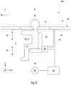
- the Fig. 6 shows a schematic sectional view of the rollover protection system 19B.
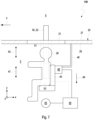
- the Fig. 7 shows another schematic sectional view of the rollover protection system 19B. The following is the Fig. 5 to 7 simultaneously referred to.
- the rollover protection system 19B is essentially the same in terms of its structure and functionality as the rollover protection system 19A. Therefore, only the differences between the rollover protection system 19B and the rollover protection system 19A will be discussed below. All previous statements regarding the rollover protection system 19A are applicable to the rollover protection system 19B and vice versa.
- the rollover protection system 19B can be placed to the right of the hatch opening 21 when viewed along the direction of travel F.
- the rollover protection system 19B can also be placed to the left of the hatch opening 21 when viewed along the direction of travel F.
- such a rollover protection system 19B can also be placed to the left and right of the hatch opening 21 when viewed along the direction of travel F.
- the rollover protection system 19B is particularly suitable for vehicle weights of more than 20 tons.
- the rollover protection system 19B does not have a protective element 30 with a protective bar 31, but rather a stamp-shaped protective element 50.
- the protective element 50 can be the Fig. 5 and 6 shown retracted state Z1 into a position shown in the Fig. 7 shown extended state Z2 and vice versa.
- the protective element 50 is slidably received in a guide sleeve 51.
- the guide sleeve 51 is firmly connected to a supporting structure of the vehicle cell 2 or the vehicle 1.
- the guide sleeve 51 is welded to the wall 20.
- the protective element 50 can be moved out of the guide sleeve 51 and back into it in order to move the protective element 50 from the retracted state Z 1 to the extended state Z2 and vice versa, as shown in the Fig. 6 and 7 is indicated by a double arrow 52.
- the protective element 50 can be arranged flush with the outer side 27 of the wall 20 or can be set back behind it.
- the protective element 50 is assigned an actuator 53, which can be integrated into the guide sleeve 51.
- the actuator 53 can also be referred to as an actuator or as a control element.
- the actuator 53 is suitable for moving the protective element 50 from the retracted state Z1 to the extended state Z2 within a few hundredths of a second.
- the actuator 53 can also be suitable for moving the protective element 50 from the extended state Z2 back to the retracted state Z1. However, this is not absolutely necessary.
- the actuator 53 is a hydraulic cylinder or a pneumatic cylinder.
- the protective element 50 can be a piston of the hydraulic cylinder or the pneumatic cylinder.
- the actuator 53 can also be an electric motor, in particular a linear motor, or have an electric motor.
- the actuator 53 can also comprise a gas generator, in particular a pyrotechnic gas generator. In this case, the actuator 53 is only suitable for a one-time movement of the protective element 30 from the retracted state Z1 to the extended state Z2.
- the rollover protection system 19B also comprises a sensor system 43, a control and regulating unit 44, with which the actuator 53 is operatively connected, a support element 45 and an adjustment unit 46, which can be suspended from the wall 20 by means of a suspension 48.
- the support element 45 it is also possible for the support element 45 to be automatically retracted into the interior 3 at the same time as the actuator 53 is triggered, so that the crew member 29 is completely inside the interior 3 in the event of a rollover of the vehicle 1, as was already explained above with reference to the rollover protection system 19A.
- the regulation and control unit 44 detects, based on sensor signals from the sensor system 43, a rollover of the vehicle 1 or a limit value of a tilting of the vehicle 1 about the x-direction x and/or the z-direction z, at which a rollover of the vehicle 1 is to be expected.
- the respective actuator 41, 53 is not activated and the protective element 30, 50 is in the retracted state Z1.
- the protective element 30, 50 can lock or block itself in the extended state Z2.
- a mechanical locking device can be provided, for example.
- This locking device can be or have a pawl, for example, which engages positively in the protective element 30, 50 in the extended state Z2.
- a positive connection is created by at least two components engaging one another or behind one another. Positive connections are connections that can be released again.
- the protective element 30, 50 locks in the extended state Z2, it is prevented, for example, that the protective element 30, 50 is undesirably moved from the extended state Z2 back to the retracted state Z1 by the weight force G of the vehicle 1 acting on it. This also prevents the actuator 41, 53 from being loaded with the entire weight force G of the vehicle 1. Damage to or overloading of the actuator 41, 53 is thereby avoided.
- the actuator 41, 53 represents the physical conversion of energy.
- the actuator 41, 53 can function in a variety of ways. Only a few possible operating principles of the actuator 41, 53 are explained below.
- the actuator 41, 53 can function mechanically in particular.
- the actuator 41, 53 can have spring elements, in particular pre-tensioned spring assemblies, for example.
- the actuator 41, 53 can work hydraulically.
- a simple or telescopic hydraulic cylinder can be used as the actuator 41, 53.
- An electrically operating actuator 41, 53 is also possible.
- a motor with an adjustment device can be used as the actuator 41, 53.
- the actuator 41, 53 can also have an explosive charge.
- the advantages of the embodiments of the rollover protection system 19A, 19B are that the protective element 30, 50 does not remain permanently outside the vehicle 1, in particular the vehicle cell 2. Furthermore, the rollover protection system 19A, 19B is designed for the high weight G of the vehicle 1 of over 20 tons. Depending on the embodiment of the rollover protection system 19A, 19B, it can be subsequently integrated into a vehicle (not shown) without such a rollover protection system 19A, 19B with minimal effort. The rollover protection system 19A, 19B can therefore be retrofitted.
- the rollover protection system 19A, 19B also enables protection of components that are mounted on the outside of the vehicle 1 or on the vehicle cell 2.
- the rollover protection system 19A, 19B does not result in any additional restrictions on visibility due to its extendability.
- the variable structure of the rollover protection system 19A, 19B enables the protection of the crew member 29 if the vehicle 1 rolls over. In the event of the vehicle 1 rolling over, the rollover protection system 19A, 19B can be used to prevent serious or fatal injuries to the crew member 29.
- the rollover protection system 19A, 19B itself can be designed in such a way that it fulfills a dual function.
- the rollover protection system 19A, 19B can be designed in such a way that it can be used by rescue workers to roll the vehicle 1 back onto the wheels 11, 12, 13, 14. This dual functionality results from the previously mentioned telescopic nature of the rollover protection system 19A, 19B.
- the actuator 41, 53 can function purely mechanically.
- the actuator 41, 53 can have pre-tensioned spring assemblies, for example.
- the actuator 41, 53 can be a hydraulic cylinder or have a hydraulic cylinder.
- the hydraulic cylinder can be simple or telescopic.
- the actuator 41, 53 can comprise, for example, an electric motor with an adjustment device.
- the actuator 41, 53 can also function explosively.
- a gas generator in particular a pyrotechnic one, can be used as the actuator 41, 53.
- Combinations of the aforementioned operating principles can also be used. Electromechanical operating principles are particularly conceivable here.
- the different designs of the operating principle of the actuator 41, 53 offer further advantages in addition to the direct mechanical implementation.
- the protective elements 30, 50 can be integrated at different points on the vehicle 1. This would mean that the crew member 29 or several crew members 29 can be protected at the same time. Similar advantages are also offered with an electrical or explosive implementation.
- the actuator 41, 53 can be designed in such a way that it jams after a single activation. This avoids, for example, the actuator 41, 53 having to be designed for excessive forces.
- a reversible implementation can be used, for example, in the case of a dual function as mentioned above. With the help of the actuator 41, 53, the respective protective element 30, 50 can then be raised and lowered again separately.
Landscapes
- Engineering & Computer Science (AREA)
- General Engineering & Computer Science (AREA)
- Mechanical Engineering (AREA)
- Aiming, Guidance, Guns With A Light Source, Armor, Camouflage, And Targets (AREA)
Applications Claiming Priority (1)
| Application Number | Priority Date | Filing Date | Title |
|---|---|---|---|
| DE102023108238.8A DE102023108238A1 (de) | 2023-03-30 | 2023-03-30 | Überrollschutzsystem und geschütztes fahrzeug |
Publications (1)
| Publication Number | Publication Date |
|---|---|
| EP4438996A1 true EP4438996A1 (fr) | 2024-10-02 |
Family
ID=90364562
Family Applications (1)
| Application Number | Title | Priority Date | Filing Date |
|---|---|---|---|
| EP24162725.6A Pending EP4438996A1 (fr) | 2023-03-30 | 2024-03-11 | Système de protection contre le retournement et véhicule protégé |
Country Status (2)
| Country | Link |
|---|---|
| EP (1) | EP4438996A1 (fr) |
| DE (1) | DE102023108238A1 (fr) |
Citations (6)
| Publication number | Priority date | Publication date | Assignee | Title |
|---|---|---|---|---|
| DE3516671A1 (de) * | 1985-05-09 | 1986-11-13 | Wolfram Prof. Dr.-Ing. 2070 Grosshansdorf Funk | Gepanzertes schuetzenfahrzeug |
| DE102004044584A1 (de) * | 2003-09-18 | 2005-04-14 | Franz-Ernst Englisch | Überrollschützsystem für Fahrzeuge |
| US20050115395A1 (en) * | 2002-04-05 | 2005-06-02 | Giat Industries | Device for protecting a vehicle roof |
| US20060273566A1 (en) * | 2003-05-22 | 2006-12-07 | Eugen Hepner | Military motor vehicle for transporting personnel |
| DE102006006659B3 (de) * | 2006-02-14 | 2007-06-21 | Automotive Group Ise Innomotive Systems Europe Gmbh | Überrollschutzsystem für Kraftfahrzeuge mit einem annähernd fahrzeugbreiten aktiv aufstellbaren Überrollbügel |
| US7413247B2 (en) * | 2004-08-19 | 2008-08-19 | H. Koch & Sons Co., Inc. | Occupant retraction system |
Family Cites Families (3)
| Publication number | Priority date | Publication date | Assignee | Title |
|---|---|---|---|---|
| DE10027753C1 (de) * | 2000-06-03 | 2001-09-06 | Ise Gmbh | Überrollschutzvorrichtung für Kraftfahrzeuge mit einem pyrotechnischen und einem weiteren, sich bei der Auslösung nicht verbrauchenden Aktuator |
| DE10317314B3 (de) * | 2003-04-14 | 2004-07-22 | Schroth Safety Products Gmbh | Einrichtung zur Positionierung eines Besatzungsmitglieds eines Fahrzeugs |
| DE102006007368A1 (de) * | 2006-02-17 | 2007-08-23 | Krauss-Maffei Wegmann Gmbh & Co. Kg | Verfahren und Vorrichtung zum Personenschutz an einem Fahrzeug, insbesondere an einem Fahrschulfahrzeug |
-
2023
- 2023-03-30 DE DE102023108238.8A patent/DE102023108238A1/de active Pending
-
2024
- 2024-03-11 EP EP24162725.6A patent/EP4438996A1/fr active Pending
Patent Citations (6)
| Publication number | Priority date | Publication date | Assignee | Title |
|---|---|---|---|---|
| DE3516671A1 (de) * | 1985-05-09 | 1986-11-13 | Wolfram Prof. Dr.-Ing. 2070 Grosshansdorf Funk | Gepanzertes schuetzenfahrzeug |
| US20050115395A1 (en) * | 2002-04-05 | 2005-06-02 | Giat Industries | Device for protecting a vehicle roof |
| US20060273566A1 (en) * | 2003-05-22 | 2006-12-07 | Eugen Hepner | Military motor vehicle for transporting personnel |
| DE102004044584A1 (de) * | 2003-09-18 | 2005-04-14 | Franz-Ernst Englisch | Überrollschützsystem für Fahrzeuge |
| US7413247B2 (en) * | 2004-08-19 | 2008-08-19 | H. Koch & Sons Co., Inc. | Occupant retraction system |
| DE102006006659B3 (de) * | 2006-02-14 | 2007-06-21 | Automotive Group Ise Innomotive Systems Europe Gmbh | Überrollschutzsystem für Kraftfahrzeuge mit einem annähernd fahrzeugbreiten aktiv aufstellbaren Überrollbügel |
Also Published As
| Publication number | Publication date |
|---|---|
| DE102023108238A1 (de) | 2024-10-02 |
Similar Documents
| Publication | Publication Date | Title |
|---|---|---|
| DE102004006819B4 (de) | Fahrzeug mit Schutz gegen die Wirkung einer Landmine | |
| DE19514569A1 (de) | An einem Trägerfahrzeug, insbesondere einem Kampfpanzer, installierte Such- und Räumeinrichtung für Landminen, sowie Verfahren zur Ortung und Zerstörung einer Landmine mittels dieser Such- und Räumeinrichtung | |
| DE102008047583A1 (de) | Schutzdachaufbau für den Führerstand einer Baumaschine | |
| EP1549815B1 (fr) | Systeme d'ouverture d'urgence de portieres de vehicules automobiles | |
| DE102014108380A1 (de) | Dämpfungsmodul für einen Fahrzeugsitz | |
| EP4438996A1 (fr) | Système de protection contre le retournement et véhicule protégé | |
| EP1820688A2 (fr) | Dispositif et procédé destinés à la protection des personnes dans un véhicule, en particulier dans un véhicule d'auto-école | |
| EP4438998B1 (fr) | Système de protection contre le retournement et véhicule protégé | |
| EP4438995B1 (fr) | Véhicule protégé | |
| DE102023108245A1 (de) | Überrollschutzsystem und geschütztes fahrzeug | |
| DE102012001995B4 (de) | Fahrzeug mit einem Zwischenboden | |
| DE202013001302U1 (de) | Zugangssystem zu einer Baumaschine, einer Lademaschine oder einer anderen mobilen Arbeitsmaschine | |
| EP4438997B1 (fr) | Véhicule protégé avec système de protection contre le retournement | |
| EP2589919A1 (fr) | Véhicule blindé exposé aux mines | |
| EP3096108B1 (fr) | Vehicule militaire | |
| EP2120001B1 (fr) | Véhicule blindé avec trou d'homme fermable par un couvercle | |
| EP2652434B1 (fr) | Portière de véhicule pour véhicules blindés | |
| EP4356064B1 (fr) | Véhicule blindé avec trappe de sortie de secours disposée dans le plancher du véhicule | |
| DE102023103529A1 (de) | Teleskopabstützstange und Nutzfahrzeug | |
| DE102023119107A1 (de) | Nutzfahrzeug | |
| DE102023133598A1 (de) | Schiebetürmodul, turm und fahrzeug | |
| EP2386818A1 (fr) | Dispositif à l'exploration d'environs pour un véhicule et procédure de sa production | |
| DE102023115802A1 (de) | Beobachtungskuppel für ein militärisches Fahrzeug | |
| DE102022104421A1 (de) | Geschütztes fahrzeug und verfahren | |
| EP2705980A1 (fr) | Siège de sécurité et procédé de réduction de la force s'exerçant sur une personne |
Legal Events
| Date | Code | Title | Description |
|---|---|---|---|
| PUAI | Public reference made under article 153(3) epc to a published international application that has entered the european phase |
Free format text: ORIGINAL CODE: 0009012 |
|
| STAA | Information on the status of an ep patent application or granted ep patent |
Free format text: STATUS: REQUEST FOR EXAMINATION WAS MADE |
|
| 17P | Request for examination filed |
Effective date: 20240311 |
|
| AK | Designated contracting states |
Kind code of ref document: A1 Designated state(s): AL AT BE BG CH CY CZ DE DK EE ES FI FR GB GR HR HU IE IS IT LI LT LU LV MC ME MK MT NL NO PL PT RO RS SE SI SK SM TR |