EP4453358B1 - Beschlag zur bewegbaren lagerung eines schwenkelements - Google Patents
Beschlag zur bewegbaren lagerung eines schwenkelements Download PDFInfo
- Publication number
- EP4453358B1 EP4453358B1 EP22834468.5A EP22834468A EP4453358B1 EP 4453358 B1 EP4453358 B1 EP 4453358B1 EP 22834468 A EP22834468 A EP 22834468A EP 4453358 B1 EP4453358 B1 EP 4453358B1
- Authority
- EP
- European Patent Office
- Prior art keywords
- furniture
- fitting
- hinge pin
- fitting part
- pivoting element
- Prior art date
- Legal status (The legal status is an assumption and is not a legal conclusion. Google has not performed a legal analysis and makes no representation as to the accuracy of the status listed.)
- Active
Links
Images


Classifications
-
- E—FIXED CONSTRUCTIONS
- E05—LOCKS; KEYS; WINDOW OR DOOR FITTINGS; SAFES
- E05D—HINGES OR SUSPENSION DEVICES FOR DOORS, WINDOWS OR WINGS
- E05D15/00—Suspension arrangements for wings
- E05D15/56—Suspension arrangements for wings with successive different movements
- E05D15/58—Suspension arrangements for wings with successive different movements with both swinging and sliding movements
-
- E—FIXED CONSTRUCTIONS
- E05—LOCKS; KEYS; WINDOW OR DOOR FITTINGS; SAFES
- E05D—HINGES OR SUSPENSION DEVICES FOR DOORS, WINDOWS OR WINGS
- E05D15/00—Suspension arrangements for wings
- E05D15/26—Suspension arrangements for wings for folding wings
- E05D15/262—Suspension arrangements for wings for folding wings folding vertically
-
- E—FIXED CONSTRUCTIONS
- E05—LOCKS; KEYS; WINDOW OR DOOR FITTINGS; SAFES
- E05D—HINGES OR SUSPENSION DEVICES FOR DOORS, WINDOWS OR WINGS
- E05D15/00—Suspension arrangements for wings
- E05D15/26—Suspension arrangements for wings for folding wings
- E05D15/264—Suspension arrangements for wings for folding wings for bi-fold wings
-
- E—FIXED CONSTRUCTIONS
- E05—LOCKS; KEYS; WINDOW OR DOOR FITTINGS; SAFES
- E05D—HINGES OR SUSPENSION DEVICES FOR DOORS, WINDOWS OR WINGS
- E05D3/00—Hinges with pins
- E05D3/06—Hinges with pins with two or more pins
-
- E—FIXED CONSTRUCTIONS
- E05—LOCKS; KEYS; WINDOW OR DOOR FITTINGS; SAFES
- E05D—HINGES OR SUSPENSION DEVICES FOR DOORS, WINDOWS OR WINGS
- E05D3/00—Hinges with pins
- E05D3/06—Hinges with pins with two or more pins
- E05D3/12—Hinges with pins with two or more pins with two parallel pins and one arm
-
- E—FIXED CONSTRUCTIONS
- E05—LOCKS; KEYS; WINDOW OR DOOR FITTINGS; SAFES
- E05D—HINGES OR SUSPENSION DEVICES FOR DOORS, WINDOWS OR WINGS
- E05D3/00—Hinges with pins
- E05D3/06—Hinges with pins with two or more pins
- E05D3/18—Hinges with pins with two or more pins with sliding pins or guides
-
- E—FIXED CONSTRUCTIONS
- E05—LOCKS; KEYS; WINDOW OR DOOR FITTINGS; SAFES
- E05D—HINGES OR SUSPENSION DEVICES FOR DOORS, WINDOWS OR WINGS
- E05D5/00—Construction of single parts, e.g. the parts for attachment
- E05D5/02—Parts for attachment, e.g. flaps
- E05D5/08—Parts for attachment, e.g. flaps of cylindrical shape
-
- E—FIXED CONSTRUCTIONS
- E05—LOCKS; KEYS; WINDOW OR DOOR FITTINGS; SAFES
- E05Y—INDEXING SCHEME ASSOCIATED WITH SUBCLASSES E05D AND E05F, RELATING TO CONSTRUCTION ELEMENTS, ELECTRIC CONTROL, POWER SUPPLY, POWER SIGNAL OR TRANSMISSION, USER INTERFACES, MOUNTING OR COUPLING, DETAILS, ACCESSORIES, AUXILIARY OPERATIONS NOT OTHERWISE PROVIDED FOR, APPLICATION THEREOF
- E05Y2900/00—Application of doors, windows, wings or fittings thereof
- E05Y2900/20—Application of doors, windows, wings or fittings thereof for furniture, e.g. cabinets
-
- E—FIXED CONSTRUCTIONS
- E05—LOCKS; KEYS; WINDOW OR DOOR FITTINGS; SAFES
- E05Y—INDEXING SCHEME ASSOCIATED WITH SUBCLASSES E05D AND E05F, RELATING TO CONSTRUCTION ELEMENTS, ELECTRIC CONTROL, POWER SUPPLY, POWER SIGNAL OR TRANSMISSION, USER INTERFACES, MOUNTING OR COUPLING, DETAILS, ACCESSORIES, AUXILIARY OPERATIONS NOT OTHERWISE PROVIDED FOR, APPLICATION THEREOF
- E05Y2900/00—Application of doors, windows, wings or fittings thereof
- E05Y2900/20—Application of doors, windows, wings or fittings thereof for furniture, e.g. cabinets
- E05Y2900/212—Doors disappearing in pockets in the furniture body
Definitions
- the invention relates to a piece of furniture comprising a pivoting element, a stationary support and at least one fitting for the movable mounting of the pivoting element, in particular of a furniture part, relative to the stationary support, with the features of the preamble of claim 1.
- Such a fitting is, for example, from the applicant’s own document AT 521841 A1 , the WO2018/129574A1 or from one of the writings US 2004/0252045 A1 , DE 202 07 036 U1 , EP 3 343 152 A1 and WO 2020/232490 A1
- This document proposes a joint mechanism with at least five joint axes and several joint levers.
- the disadvantage of such a fitting is the relatively complex design of the joint mechanism. On the one hand, this leads to increased material requirements and manufacturing effort, which in turn results in higher costs. On the other hand, a complex joint mechanism mechanism is more susceptible to contamination, defects, etc.
- the AT 521841 A1 also discloses a piece of furniture with such a hinge.
- a pivoting element can cover an end face of a side wall at least partially, preferably substantially completely.
- the furniture when viewed from the front, presents a smooth surface overall—without the formation of a step or gap visible from the front between the side wall and the pivoting element. This positive effect is to be maintained.
- the DE102009009719A1 discloses a furniture fitting with a guide device.
- the objective technical problem of the present invention is therefore to provide a piece of furniture which is improved over the prior art and in which the disadvantages of the prior art are at least partially eliminated and which in particular retains the above-mentioned positive effect.
- a guide device is provided, wherein the guide device is mounted so as to be linearly displaceable on or in one of the two fitting parts and is articulated to the other of the two fitting parts via a third joint axis, wherein the third joint axis is formed separately and spaced apart from the first joint axis and the second joint axis, wherein at least two, preferably exactly two, articulated levers are provided, wherein the at least two articulated levers are each articulated to the first fitting part via the first joint axis and articulated to the second fitting part via the second joint axis.
- the guide device enables a reduction to three joint axes, which in turn reduces the complexity of the joint mechanism and thus of the fitting.
- the arrangement of the joint axes allows a pivoting element to cover at least part of the end face of a side wall, preferably essentially completely.
- the swivel element is already stabilized by the fitting. Furthermore, vertical load transfer can be achieved via a single articulated lever.
- damping of the pivoting movement of the pivoting element in a proposed fitting can be easily achieved by means of a drill-in damper.
- the furniture comprises a pivoting element, a stationary support and at least one fitting, wherein the pivoting element is designed in the form of a movable furniture part and the stationary support is designed in the form of a furniture body.
- the pivoting element is movable by means of the fitting between a first position in which the pivoting element at least partially covers an end face of the side wall and a second position in which the pivoting element is movable in a depth direction of the stationary support.
- the at least one articulated lever is substantially L-shaped.
- the L-shaped design of the at least one articulated lever in conjunction with the arrangement of the joint axes, makes it possible to specify a trajectory along which a pivoting element can be pivoted.
- the guide device comprises a guide element and a bearing element, wherein the guide element is mounted in the bearing element in a linearly displaceable manner.
- the guide element has a connecting section via which the guide element is connected in an articulated manner to one of the two fitting parts via the third joint axis.
- the guide element has a circular or polygonal cross-sectional area.
- a cross-section can be selected which allows or prevents rotation of the guide element in the bearing element.
- the bearing element comprises at least one sliding element, preferably two sliding elements.
- the at least one sliding element is arranged in a recess in the first fitting part, wherein the guide element is guided in the sliding element in a linearly displaceable manner.
- the second fitting part is formed in two parts.
- the second joint axis is assigned to a first part of the second fitting and the third joint axis is assigned to a second part of the second fitting.
- the two-part design of the second fitting component allows for the separate and spaced design of the joint axes. Furthermore, material can be saved in the second fitting component.
- the pivoting element in the second position is arranged substantially parallel to the side wall.
- the stationary support has at least two side walls, wherein the at least two side walls form a cavity in which the
- Swivel element can be moved in the second position in the depth direction of the stationary support.
- a pivoting element In the second position, a pivoting element is barely visible, which, on the one hand, prevents the pivoting element from extending beyond the furniture and, on the other hand, promotes a visually appealing overall appearance of the furniture.
- at least two fittings according to the invention can be provided.
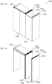
- the Figure 1 shows a perspective view of a piece of furniture 100 in a first position
- the Figure 2 the same furniture 100 in a second position.
- the furniture 100 has a stationary support 102 in the form of a furniture body.
- a pivoting element 101 in the form of a door leaf is also visible.
- the pivoting element 101 covers an end face 103a of a side wall 103.
- the pivoting element 101 furthermore adjoins a folding sliding door 105 flush, which in the first position results in a continuous furniture front and thus a visually appealing overall appearance of the furniture 100.
- a second side wall 103 is provided, the side walls 103 forming a cavity 104.
- a part of the furniture 100 adjoining the pivoting element 101 is equipped with a folding sliding door 105, which can be arranged in a cavity 104' formed by two other side walls 103'.
- pivoting element 101 no further part adjoins the pivoting element 101, i.e., that the stationary support 102 is essentially the same width as the pivoting element 101.
- the stationary support 102 is essentially the same width as the pivoting element 101.
- several identical pivoting elements 101 can also be arranged next to one another.
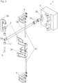
- the Figure 2 shows an exploded view of a fitting 1.
- the first fitting part 2 has a recess 2b into which two bearing elements 5e can be inserted.
- the bearing elements 5e can be made of a different material than the first fitting part 2, for example, to achieve better sliding properties. It is also conceivable that only one bearing element 5e or more than two bearing elements 5e are provided.
- a guide element 5b is guided in the bearing elements 5e.
- both the bearing elements 5e and the guide element 5b have a circular cross-section, but essentially any other cross-section is conceivable.
- the guide element 5b has a connecting section 5d, via which the guide element 5b can be connected to the second part 3b of the second fitting part 3.
- a bore is provided in the connecting section 5d, which can accommodate a connecting pin 6. Bores for receiving the connecting pin 6 are also provided in the second part 3b, thus realizing an articulated connection between the guide element 5b and the second fitting part 3.
- the articulated levers 4 are also connected to the first fitting part 2 and the first part 3a of the second fitting part 3 via connecting pins 6.
- two articulated levers 4 are provided, which has the advantage of being able to absorb higher forces and moments.
- more than two articulated levers 4 can also be provided.
- both articulated levers 4 are articulated to the first fitting part 2 and the second fitting part 3 via the same joint axes 2a, 3c.
- the articulated levers 4 cannot move independently, but only simultaneously with one another.
- the second articulated lever 4 thus serves only to structurally reinforce the first articulated lever 4.
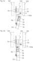
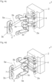
- the Figures 3a to 3d show plan views of a part of a piece of furniture 100 at various steps when transferring the piece of furniture 100 from a first to a second position and the Figures 4a to 4d Perspective views of a fitting 1 with the same steps.
- the swivel element 101 is even further and in the 3D figures and 4d pivoted into the second position. It can be seen that the pivoting element 101 is guided by the articulated levers 4 and the arrangement of the joint axes 2a, 3c, 5a in such a way that in the first position the end face 103a of the side wall 103 is concealed, but in the second position it is arranged parallel to the side wall 103 and can be moved into a cavity 104 formed by the side wall 103 and another side wall 103. This The movement takes place in a depth direction Z of the stationary support 102 or the cavity 104.
Landscapes
- Engineering & Computer Science (AREA)
- Mechanical Engineering (AREA)
- Hinges (AREA)
- Hinge Accessories (AREA)
Description
- Die Erfindung betrifft ein Möbel umfassend ein Schwenkelement, einen stationären Träger und zumindest einen Beschlag zur bewegbaren Lagerung des Schwenkelements, insbesondere eines Möbelteils, relativ zu dem stationären Träger, mit den Merkmalen des Oberbegriffs des Anspruchs 1.
- Ein solcher Beschlag ist beispielsweise aus der anmeldereigenen Schrift
AT 521841 A1 WO2018/129574A1 oder auch aus einer der SchriftenUS 2004/0252045 A1 ,DE 202 07 036 U1 ,EP 3 343 152 A1 undWO 2020/232490 A1 bekannt. Diese Schrift schlägt einen Gelenkmechanismus mit zumindest 5 Gelenkachsen und mehreren Gelenkhebeln vor. Nachteilig an einem solchen Beschlag ist die verhältnismäßig komplexe Ausbildung des Gelenkmechanismus. Dies führt einerseits zu einem erhöhten Materialbedarf und Fertigungsaufwand, was höhere Kosten mit sich bringt. Andererseits ist eine komplexe Mechanik des Gelenkmechanismus anfälliger für Verunreinigung, Defekte o.Ä. - Die
AT 521841 A1 - Die
DE102009009719A1 offenbart einen Möbelbeschlag mit einer Führungsvorrichtung. - Die objektive technische Aufgabe der vorliegenden Erfindung besteht daher darin, einen gegenüber dem Stand der Technik verbessertes Möbel anzugeben, bei welchem die Nachteile des Stands der Technik zumindest teilweise behoben sind, und welche insbesondere den oben genannten positiven Effekt beibehält.
- Diese Aufgabe wird durch die Merkmale des Anspruchs 1 gelöst.
- Es ist demnach eine Führungsvorrichtung vorgesehen, wobei die Führungsvorrichtung linear verschiebbar an oder in einem der beiden Beschlagteile gelagert und mit dem anderen der beiden Beschlagteile über eine dritte Gelenkachse gelenkig verbunden ist, wobei die dritte Gelenkachse gesondert und beabstandet von der ersten Gelenkachse und der zweiten Gelenkachse ausgebildet ist, wobei wenigstens zwei, vorzugsweise genau zwei, Gelenkhebel vorgesehen sind, wobei die wenigstens zwei Gelenkhebel jeweils über die erste Gelenkachse gelenkig mit dem ersten Beschlagteil und über die zweite Gelenkachse gelenkig mit dem zweiten Beschlagteil verbunden sind.
- Die Führungsvorrichtung ermöglich die Reduktion auf drei Gelenkachsen, wodurch wiederum die Komplexität des Gelenkmechanismus und somit des Beschlags reduziert werden kann. Durch die Anordnung der Gelenkachsen wird ermöglicht, dass ein Schwenkelement eine Stirnseite einer Seitenwand zumindest abschnittsweise, vorzugsweise im Wesentlichen vollständig, abdeckt.
- Außerdem wird dadurch das Schwenkelement bereits durch den Beschlag stabilisiert. Zudem kann ein vertikaler Lastabtrag über nur einen Gelenkhebel erfolgen.
- Weiters lässt sich eine Dämpfung einer Schwenkbewegung des Schwenkelements bei einem vorgeschlagenen Beschlag leicht mittels eines Einbohrdämpfers realisieren.
- Erfindungsgemäß ist vorgesehen, dass das Möbel ein Schwenkelement, einen stationären Träger und zumindest einen Beschlag umfasst, wobei das Schwenkelement in Form eines beweglichen Möbelteils und der stationäre Träger in Form eines Möbelkorpus ausgebildet sind.
- Erfindungsgemäß ist vorgesehen, dass das Schwenkelement mittels des Beschlags zwischen einer ersten Stellung, in welcher das Schwenkelement eine Stirnseite der Seitenwand zumindest teilweise abdeckt, und einer zweiten Stellung, in welcher das Schwenkelement in eine Tiefenrichtung des stationären Trägers verfahrbar ist, bewegbar ist.
- Dadurch ist bei einer Ansicht des Möbels von vorne insgesamt eine glatte Oberfläche - ohne die Bildung einer von vorne ersichtlichen Stufe oder Spaltes zwischen der Seitenwand und dem Schwenkelement - vorhanden. Das optische Gesamtbild eines Möbels wird somit deutlich aufgewertet.
- Vorteilhafte Ausführungsformen der Erfindung sind in den abhängigen Ansprüchen definiert.
- Gemäß einer vorteilhaften Ausgestaltung der Erfindung kann vorgesehen sein, dass der wenigstens eine Gelenkhebel im Wesentlichen L-förmig ausgebildet ist.
- Die L-förmige Ausbildung des wenigstens einen Gelenkhebels ermöglicht es in Verbindung mit der Anordnung der Gelenkachsen eine Trajektorie vorzugeben, entlang welcher ein Schwenkelement verschwenkt werden kann.
- Es kann auch vorgesehen sein, dass die Führungsvorrichtung ein Führungselement und ein Lagerungselement umfasst, wobei das Führungselement linear verschiebbar in dem Lagerungselement gelagert ist.
- Zudem kann vorgesehen sein, dass das Führungselement einen Verbindungsabschnitt aufweist, über welchen das Führungselement über die dritte Gelenkachse gelenkig mit einem der beiden Beschlagteile verbunden ist.
- Das stellt einfache und unkomplizierte Möglichkeiten zur Umsetzung einer Führungsvorrichtung dar.
- Gemäß einer vorteilhaften Ausführungsform der Erfindung kann vorgesehen sein, dass das Führungselement eine kreisförmige oder polygonförmige Querschnittsfläche aufweist.
- Je nach Anforderung kann so ein Querschnitt gewählt werden, welcher eine Verdrehung des Führungselements in dem Lagerelement zulässt oder verhindert.
- Es kann vorgesehen sein, dass das Lagerungselement wenigstens ein Gleitelement, vorzugsweise zwei Gleitelemente, umfasst.
- Dabei hat es sich insbesondere als vorteilhaft erwiesen, wenn das wenigstens eine Gleitelement in einer Ausnehmung im ersten Beschlagteil angeordnet ist, wobei das Führungselement in dem Gleitelement linear verschiebbar geführt ist.
- Dadurch ist es möglich, das Material der Gleitelemente unabhängig vom Material der Beschläge auszuwählen. Zudem können die Gleitelemente bei eventuell auftretendem Verschleiß einfach ausgetauscht werden.
- Bevorzugt kann vorgesehen sein, dass das zweite Beschlagteil zweiteilig ausgebildet ist.
- Besonders bevorzugt kann vorgesehen sein, dass die zweite Gelenksachse einem ersten Teil des zweiten Beschlags und die dritte Gelenksachse einem zweiten Teil des zweiten Beschlags zugeordnet ist.
- Über die zweiteilige Ausbildung des zweiten Beschlagteils kann die gesonderte und beabstandete Ausbildung der Gelenkachsen einfach realisiert werden. Weiters kann Material beim zweiten Beschlagteil eingespart werden.
- Bevorzugt kann vorgesehen sein, dass das Schwenkelement in der zweiten Stellung im Wesentlichen parallel zu der Seitenwand angeordnet ist.
- Durch die parallele Anordnung des Schwenkelements mit der Seitenwand in der zweiten Stellung ist ein Innenraum des Möbels in der zweiten Stellung leicht zugänglich.
- Besonders bevorzugt kann vorgesehen sein, dass der stationäre Träger zumindest zwei Seitenwände aufweist, wobei die zumindest zwei Seitenwände einen Hohlraum bilden, in welchen das
- Schwenkelement in der zweiten Stellung in Tiefenrichtung des stationären Trägers verfahrbar ist.
- In der zweiten Stellung ist ein Schwenkelement also kaum mehr ersichtlich, wodurch sich einerseits das Schwenkelement nicht über das Möbel hinaus erstreckt und andererseits ein optisch ansprechendes Gesamtbild des Möbels begünstigt wird. Gemäß einem bevorzugten Ausführungsbeispiel der Erfindung kann vorgesehen sein, dass zumindest zwei erfindungsgemäße Beschläge vorgesehen sind.
- Dies erhöht die Stabilität eines Möbels deutlich.
- Weitere Einzelheiten und Vorteile der vorliegenden Erfindung werden anhand der Figurenbeschreibung unter Bezugnahme auf die in den Zeichnungen dargestellten Ausführungsbeispiele im Folgenden näher erläutert. Darin zeigen:
- Fig. 1a
- eine perspektivische Ansicht eines Möbels in einer ersten Stellung,
- Fig. 1b
- eine perspektivische Ansicht eines Möbels in einer zweiten Stellung,
- Fig. 2
- eine Explosionsdarstellung eines Beschlags,
- Fig. 3a-d
- Draufsichten auf einen Teil eines Möbels bei verschiedenen Schritten beim Überführen des Möbels von einer ersten in eine zweite Stellung, und
- Fig. 4a-d
- perspektivische Ansichten eines Beschlags bei verschiedenen Schritten beim Überführen des Möbels von einer ersten in eine zweite Stellung.
- Die
Figur 1 zeigt eine perspektivische Ansicht eines Möbels 100 in einer ersten Stellung, dieFigur 2 dasselbe Möbel 100 in einer zweiten Stellung. - Es ist erkennbar, dass das Möbel 100 einen stationären Träger 102 in Form eines Möbelkorpus aufweist. Zudem ist ein Schwenkelement 101 in Form eines Türflügels ersichtlich.
- In der ersten Stellung gemäß
Figur 1a verdeckt das Schwenkelement 101 eine Stirnseite 103a einer Seitenwand 103. Das Schwenkelement 101 schließt dabei weiters bündig an eine Falt-Schiebetür 105 an, wodurch sich in der ersten Stellung eine durchgehende Möbelfront und somit ein optisch ansprechendes Gesamtbild des Möbels 100 ergibt. - Es ist auch ersichtlich, dass eine zweite Seitenwand 103 vorgesehen ist, wobei die Seitenwände 103 einen Hohlraum 104 bilden.
- In der zweiten Stellung gemäß
Figur 1b ist das Schwenkelement 101 im Wesentlichen vollständig in dem Hohlraum 104 angeordnet. Somit ist ein Innenraum 106 leicht zugänglich. Zudem erstreckt sich das Schwenkelement 101 nicht in einen Raum hinein, sodass das Schwenkelement 101 nicht im Weg ist. - Im vorliegenden Ausführungsbeispiel ist ein an das Schwenkelement 101 anschließender Teil des Möbels 100 mit einer Falt-Schiebtür 105 ausgestattet, welche in einen durch zwei andere Seitenwände 103' gebildeten Hohlraum 104' angeordnet werden kann.
- Es kann aber auch vorgesehen sein, dass hier kein weiterer Teil an das Schwenkelement 101 anschließt, d.h. dass der stationäre Träger 102 im Wesentlichen gleich breit wie das Schwenkelement 101 ist. Es können aber auch mehrere identische Schwenkelemente 101 nebeneinander angeordnet sein.
- Die
Figur 2 zeigt eine Explosionsdarstellung eines Beschlags 1. Es sind ein erstes Beschlagteil 2 und ein zweiteiliges zweites Beschlagteil 3, bestehend aus einem ersten Teil 3a und einem zweiten Teil 3b, erkennbar. - Das erste Beschlagteil 2 weist eine Ausnehmung 2b auf, in welche zwei Lagerungselement 5e eingesetzt werden können. Die Lagerungselemente 5e können dabei aus einem anderen Material als das erste Beschlagteil 2 gefertigt sein, beispielsweise um bessere Gleiteigenschaften zu erreichen. Es ist auch denkbar, dass nur ein Lagerelement 5e oder aber auch mehr als zwei Lagerelemente 5e vorgesehen ist/sind.
- In den Lagerelementen 5e ist ein Führungselement 5b geführt. Im vorliegenden Fall sind sowohl die Lagerelemente 5e als auch das Führungselement 5b von kreisförmigem Querschnitt, es ist im Wesentlichen jedoch jeder andere Querschnitt denkbar.
- Das Führungselement 5b weist einen Verbindungsabschnitt 5d auf, über welchen das Führungselement 5b mit dem zweiten Teil 3b des zweiten Beschlagteils 3 verbunden werden kann. Dazu ist im Verbindungsabschnitt 5d eine Bohrung vorgesehen, welche einen Verbindungsstift 6 aufnehmen kann. Auch in dem zweiten Teil 3b sind Bohrungen zur Aufnahme des Verbindungsstifts 6 vorgesehen, womit eine gelenkige Verbindung zwischen Führungselement 5b und zweitem Beschlagteil 3 realisiert wird.
- Auch die Gelenkhebel 4 sind über Verbindungsstifte 6 mit dem ersten Beschlagteil 2 bzw. dem ersten Teil 3a des zweiten Beschlagteils 3 gelenkig verbunden. Im vorliegenden Beispiel sind zwei Gelenkhebel 4 vorgesehen, was den Vorteil mit sich bringt, dass höhere Kräfte und Momente aufgenommen werden können. Es können aber auch mehr als zwei Gelenkhebel 4 vorgesehen sein.
- Insbesondere auch aus den folgenden Figuren geht hervor, dass beide Gelenkhebel 4 jeweils über die gleichen Gelenkachsen 2a, 3c mit dem ersten Beschlagteil 2 bzw. dem zweiten Beschlagteil 3 gelenkig verbunden sind. Die Gelenkhebel 4 können sich also nicht unabhängig, sondern nur simultan miteinander bewegen. Der zweite Gelenkhebel 4 dient somit lediglich zur strukturellen Verstärkung des ersten Gelenkhebels 4.
- Die
Figuren 3a bis 3d zeigen Draufsichten auf einen Teil eines Möbels 100 bei verschiedenen Schritten beim Überführen des Möbels 100 von einer ersten in eine zweite Stellung und dieFiguren 4a bis 4d perspektivische Ansichten eines Beschlags 1 bei denselben Schritten. - In den
Figuren 3a und4a befindet sich der Beschlag 1 und somit das Möbel 100 in einer ersten Stellung. Es ist erkennbar, dass das Schwenkelement 101 eine Stirnseite 103a der Seitenwand 103 im Wesentlichen vollständig abdeckt. Das Führungselement 5b ist im Wesentlichen vollständig innerhalb des Hohlraums 104 angeordnet. - In den
Figuren 3b und4b ist das Schwenkelement 101 bereits ein Stück weit verschwenkt. Es ist erkennbar, dass das in den Lagerelementen 5c geführte Führungselement 5b linear verschoben worden ist. Auch die Gelenkhebel 4 sind verschwenkt worden. Über die Gelenkhebel 4 und die Anordnung der Gelenkachsen 2a, 3c und 5a wird eine Trajektorie definiert, entlang welcher das Schwenkelement 101 verschwenkt wird. - In den
Figuren 3c und4c ist das Schwenkelement 101 noch weiter und in denFiguren 3d und4d in die zweite Stellung verschwenkt. Es ist erkennbar, dass das Schwenkelement 101 durch die Gelenkhebel 4 und die Anordnung der Gelenkachsen 2a, 3c, 5a so geführt wird, dass in der ersten Stellung die Stirnseite 103a der Seitenwand 103 verdeckt aber in der zweiten Stellung parallel zu der Seitenwand 103 angeordnet ist und in einen durch die Seitenwand 103 und eine weitere Seitenwand 103 gebildeten Hohlraum 104 verfahrbar ist. Diese Verfahrbewegung erfolgt dabei in eine Tiefenrichtung Z des stationären Trägers 102 bzw. des Hohlraums 104. -
- 1
- Beschlag
- 2
- Erstes Beschlagteil
2a erste Gelenkachse
2b Ausnehmung - 3
- Zweites Beschlagteil
3a erstes Teil
3b zweites Teil
3c zweite Gelenkachse - 4
- Gelenkhebel
- 5
- Führungsvorrichtung
5a dritte Gelenkachse
5b Führungselement
5c Lagerungselement
5d Verbindungsabschnitt
5e Gleitelemente - 6
- Verbindungsstift
- 100
- Möbel
- 101
- Schwenkelement
- 102
- Stationärer Träger
- 103
- Seitenwand
103a Stirnseite - 104
- Hohlraum
- 105
- Falt-Schiebetür
- 106
- Innenraum
- Z
- Tiefenrichtung
Claims (12)
- Möbel (100) umfassend ein Schwenkelement (101) in Form eines beweglichen Möbelteils, einen stationären Träger (102) in Form eines Möbelkorpus und zumindest einen Beschlag (1) zur bewegbaren Lagerung des Schwenkelements (101); relativ zu dem stationären Träger (102), der Beschlag umfassend:- ein erstes an dem stationären Träger (102) angeordnetes oder anordenbares Beschlagteil (2),- ein zweites an dem Schwenkelement (101) angeordnetes oder anordenbares Beschlagteil (3), wobei das erste Beschlagteil (2) und das zweite Beschlagteil (3) relativ zueinander schwenkbar ausgebildet sind,- wenigstens einen Gelenkhebel (4), welcher über eine erste Gelenkachse (2a) gelenkig mit dem ersten Beschlagteil (2) und über eine zweite Gelenkachse (3c) gelenkig mit dem zweiten Beschlagteil (3) verbunden ist,wobei das Schwenkelement (101) mittels des Beschlags (1) zwischen einer ersten Stellung, in welcher das Schwenkelement (101) eine Stirnseite (103a) der Seitenwand (103) des stationären Trägers (102) zumindest teilweise abdeckt und einer zweiten Stellung, in welcher das Schwenkelement (101) in eine Tiefenrichtung (Z) des stationären Trägers (102) verfahrbar ist, bewegbar ist,dadurch gekennzeichnet, dass- eine Führungsvorrichtung (5) vorgesehen ist, wobei die Führungsvorrichtung (5) linear verschiebbar an oder in einem der beiden Beschlagteile (2, 3) gelagert und mit dem anderen der beiden Beschlagteile (2, 3) über eine dritte Gelenkachse (5a) gelenkig verbunden ist, wobei die dritte Gelenkachse (5a) gesondert und beabstandet von der ersten Gelenkachse (2a) und der zweiten Gelenkachse (3c) ausgebildet ist, und dass wenigstens zwei, vorzugsweise genau zwei, Gelenkhebel (4) vorgesehen sind, wobei die wenigstens zwei Gelenkhebel (4) jeweils über die erste Gelenkachse (2a) gelenkig mit dem ersten Beschlagteil (2) und über die zweite Gelenkachse (3c) gelenkig mit dem zweiten Beschlagteil (3) verbunden sind.
- Möbel (100) nach Anspruch 1, dadurch gekennzeichnet, dass der wenigstens eine Gelenkhebel (4) im Wesentlichen L-förmig ausgebildet ist.
- Möbel (100) nach einem der Ansprüche 1 oder 2, dadurch gekennzeichnet, dass die Führungsvorrichtung (5) ein Führungselement (5b) und ein Lagerungselement (5c) umfasst, wobei das Führungselement (5) linear verschiebbar in dem Lagerungselement (5c) gelagert ist.
- Möbel (100) nach Anspruch 3, dadurch gekennzeichnet, dass das Führungselement (5b) einen Verbindungsabschnitt (5d) aufweist, über welchen das Führungselement (5b) an einer dritten Befestigungsstelle (5a) gelenkig mit einem der beiden Beschlagteile (2, 3) verbunden ist.
- Möbel (100) nach einem der Ansprüche 3 oder 4, dadurch gekennzeichnet, dass das Führungselement (5b) eine kreisförmige oder polygonförmige Querschnittsfläche aufweist.
- Möbel (100) nach einem der Ansprüche 3 bis 5, dadurch gekennzeichnet, dass das Lagerungselement (5c) wenigstens ein, vorzugsweise zwei, Gleitelement (5e) umfasst.
- Möbel (100) nach Anspruch 6, dadurch gekennzeichnet, dass das wenigstens eine Gleitelement (5e) in einer Ausnehmung (2b) im ersten Beschlagteil (2) angeordnet ist, wobei das Führungselement (5b) in dem Gleitelement (5e) linear verschiebbar geführt ist.
- Möbel (100) nach einem der Ansprüche 1 bis 7, dadurch gekennzeichnet, dass das zweite Beschlagteil (3) zweiteilig ausgebildet ist.
- Möbel (100) nach Anspruch 8, dadurch gekennzeichnet, dass die zweite Gelenksachse (3c) einem ersten Teil (3a) des zweiten Beschlags (3) und die dritte Gelenksachse (5a) einem zweiten Teil (3b) des zweiten Beschlags (3) zugeordnet ist.
- Möbel nach einem der Ansprüche 1 bis 9, dadurch gekennzeichnet, dass das Schwenkelement in der zweiten Stellung im Wesentlichen parallel zu der Seitenwand (103) angeordnet ist.
- Möbel nach Anspruch 10, dadurch gekennzeichnet, dass der stationäre Träger (102) zumindest zwei Seitenwände (103) aufweist, wobei die zumindest zwei Seitenwände (103) einen Hohlraum (104) bilden, in welchen das Schwenkelement (101) in der zweiten Stellung in Tiefenrichtung (Z) des stationären Trägers (102) verfahrbar ist.
- Möbel nach einem der Ansprüche 1 bis 11, dadurch gekennzeichnet, dass zumindest zwei Beschläge (1) vorgesehen sind.
Applications Claiming Priority (2)
| Application Number | Priority Date | Filing Date | Title |
|---|---|---|---|
| ATA51028/2021A AT525246B1 (de) | 2021-12-21 | 2021-12-21 | Beschlag zur bewegbaren Lagerung eines Schwenkelements |
| PCT/AT2022/060448 WO2023115084A1 (de) | 2021-12-21 | 2022-12-16 | Beschlag zur bewegbaren lagerung eines schwenkelements |
Publications (2)
| Publication Number | Publication Date |
|---|---|
| EP4453358A1 EP4453358A1 (de) | 2024-10-30 |
| EP4453358B1 true EP4453358B1 (de) | 2025-05-07 |
Family
ID=84688958
Family Applications (1)
| Application Number | Title | Priority Date | Filing Date |
|---|---|---|---|
| EP22834468.5A Active EP4453358B1 (de) | 2021-12-21 | 2022-12-16 | Beschlag zur bewegbaren lagerung eines schwenkelements |
Country Status (9)
| Country | Link |
|---|---|
| US (1) | US20240337141A1 (de) |
| EP (1) | EP4453358B1 (de) |
| JP (1) | JP2024544437A (de) |
| KR (1) | KR20240119315A (de) |
| CN (1) | CN118525126A (de) |
| AT (1) | AT525246B1 (de) |
| ES (1) | ES3033728T3 (de) |
| TW (1) | TWI843348B (de) |
| WO (1) | WO2023115084A1 (de) |
Families Citing this family (1)
| Publication number | Priority date | Publication date | Assignee | Title |
|---|---|---|---|---|
| AT526422B1 (de) * | 2022-11-30 | 2024-03-15 | Blum Gmbh Julius | Anordnung zur Bewegung wenigstens eines Abdeckelements |
Family Cites Families (15)
| Publication number | Priority date | Publication date | Assignee | Title |
|---|---|---|---|---|
| JPS5578775A (en) * | 1978-12-08 | 1980-06-13 | Nippon Musical Instruments Mfg | Hinge |
| FR2490709A1 (fr) * | 1980-08-01 | 1982-03-26 | Decaux Jean Claude | Charniere renforcee pour lourdes portes et portes equipees de telles charnieres |
| DE3120061A1 (de) * | 1981-05-20 | 1982-12-09 | Paul Hettich & Co, 4983 Kirchlengern | "moebelscharnier fuer tueren, klappen, sitzbankplatten o.dgl." |
| JP3862937B2 (ja) * | 2000-07-05 | 2006-12-27 | 本田技研工業株式会社 | 自動車用開閉体のヒンジ構造 |
| DE20207036U1 (de) * | 2002-05-03 | 2003-09-18 | Mepla-Werke Lautenschläger GmbH & Co. KG, 64354 Reinheim | Kreuzgelenkscharnier |
| US7068208B2 (en) * | 2003-06-16 | 2006-06-27 | Hsu-Chu Wu | Remote controlled cabinet |
| US20070159037A1 (en) * | 2006-01-10 | 2007-07-12 | Knape & Vogt Manufacturing Company | Hinge bracket for a pocket door |
| JP2009270376A (ja) * | 2008-05-09 | 2009-11-19 | Jouyou:Kk | ドア開閉機構 |
| DE102009009719A1 (de) * | 2009-02-19 | 2010-09-02 | Alexander Gass | Das winkelförmige Tür-, Möbelscharnier mit der Teleskopschiene bzw. dem einfachwirkenden Zylinder |
| US20120079683A1 (en) * | 2010-10-01 | 2012-04-05 | Spragg Kenneth L | Self-lubricating door hinge pin |
| KR102253487B1 (ko) * | 2017-01-03 | 2021-05-18 | 삼성전자주식회사 | 전선커버유닛을 포함하는 빌트인 냉장고 |
| AT519247B1 (de) * | 2017-01-13 | 2018-05-15 | Blum Gmbh Julius | Führungssystem zur Führung zumindest eines bewegbar gelagerten Türflügels |
| AT521841B1 (de) * | 2018-11-13 | 2023-02-15 | Blum Gmbh Julius | Möbelscharnier |
| AT522450B1 (de) * | 2019-05-17 | 2020-11-15 | Blum Gmbh Julius | Möbel |
| TWI737556B (zh) * | 2020-12-24 | 2021-08-21 | 瑋俐實業股份有限公司 | 具有調整平均速度減速關門功能裝置的隱藏式玻璃門鉸鍊 |
-
2021
- 2021-12-21 AT ATA51028/2021A patent/AT525246B1/de active
-
2022
- 2022-12-16 CN CN202280088018.4A patent/CN118525126A/zh active Pending
- 2022-12-16 JP JP2024537600A patent/JP2024544437A/ja active Pending
- 2022-12-16 EP EP22834468.5A patent/EP4453358B1/de active Active
- 2022-12-16 KR KR1020247023343A patent/KR20240119315A/ko active Pending
- 2022-12-16 WO PCT/AT2022/060448 patent/WO2023115084A1/de not_active Ceased
- 2022-12-16 ES ES22834468T patent/ES3033728T3/es active Active
- 2022-12-21 TW TW111149110A patent/TWI843348B/zh active
-
2024
- 2024-06-20 US US18/748,970 patent/US20240337141A1/en active Pending
Also Published As
| Publication number | Publication date |
|---|---|
| US20240337141A1 (en) | 2024-10-10 |
| KR20240119315A (ko) | 2024-08-06 |
| AT525246B1 (de) | 2023-02-15 |
| ES3033728T3 (en) | 2025-08-07 |
| TWI843348B (zh) | 2024-05-21 |
| AT525246A4 (de) | 2023-02-15 |
| JP2024544437A (ja) | 2024-12-02 |
| EP4453358A1 (de) | 2024-10-30 |
| WO2023115084A1 (de) | 2023-06-29 |
| TW202338198A (zh) | 2023-10-01 |
| CN118525126A (zh) | 2024-08-20 |
Similar Documents
| Publication | Publication Date | Title |
|---|---|---|
| EP2525031B1 (de) | Türband für eine verdeckte Anordnung zwischen Türflügel und Türzarge | |
| EP1151697B1 (de) | Verstellvorrichtung zur Neigungsverstellung der Frontblende einer Schublade | |
| EP4180601B1 (de) | Türband mit länglichem führungsschlitten | |
| EP3622149A1 (de) | Schiene zur führung eines schlittens einer möbeltüre | |
| EP3921498B1 (de) | Anordnung zur führung wenigstens einer bewegbaren möbeltür | |
| DE3348215C2 (de) | ||
| AT522450B1 (de) | Möbel | |
| EP4419771B1 (de) | Anordnung zur führung von wenigstens zwei möbeltüren | |
| DE10201636B4 (de) | Schiebedachanordnung für ein Fahrzeug | |
| EP3880916B1 (de) | Führungssystem zur führung zumindest eines bewegbar gelagerten möbelteiles | |
| AT525246B1 (de) | Beschlag zur bewegbaren Lagerung eines Schwenkelements | |
| EP4263993B1 (de) | Anordnung zur führung eines bewegbaren möbelteils | |
| AT524414B1 (de) | Möbelbeschlag und Möbel mit einem solchen Möbelbeschlag | |
| EP2523827A1 (de) | Führungsmittel mit toleranzkompensation für vernähung von dekorelementen | |
| DE102016210168B3 (de) | Türantrieb für eine Kraftwagentür | |
| EP4680821A1 (de) | Schiebetürenbeschlag und zugehörige schiebetürenanordnung | |
| DE1559893B2 (de) | Scharnier zum Anlenken einer Möbeltür an Möbel | |
| AT518048B1 (de) | Schubladenwand | |
| DE3217104C2 (de) | ||
| EP3296492A1 (de) | Führungssystem für eine schiebetür sowie schiebetür mit einem führungssystem und entsprechend ausgestattetes kraftfahrzeug | |
| EP2740872A2 (de) | Zur verdeckten Anordnung vorgesehenes Ecklager | |
| EP4242405A2 (de) | Anordnung zur führung wenigstens eines bewegbaren möbelteils | |
| DE102010011794B3 (de) | Scharnier | |
| DE3916348C2 (de) | ||
| EP1148204B1 (de) | Korpuselement mit Rolladen |
Legal Events
| Date | Code | Title | Description |
|---|---|---|---|
| STAA | Information on the status of an ep patent application or granted ep patent |
Free format text: STATUS: UNKNOWN |
|
| STAA | Information on the status of an ep patent application or granted ep patent |
Free format text: STATUS: THE INTERNATIONAL PUBLICATION HAS BEEN MADE |
|
| PUAI | Public reference made under article 153(3) epc to a published international application that has entered the european phase |
Free format text: ORIGINAL CODE: 0009012 |
|
| STAA | Information on the status of an ep patent application or granted ep patent |
Free format text: STATUS: REQUEST FOR EXAMINATION WAS MADE |
|
| 17P | Request for examination filed |
Effective date: 20240618 |
|
| AK | Designated contracting states |
Kind code of ref document: A1 Designated state(s): AL AT BE BG CH CY CZ DE DK EE ES FI FR GB GR HR HU IE IS IT LI LT LU LV MC ME MK MT NL NO PL PT RO RS SE SI SK SM TR |
|
| GRAP | Despatch of communication of intention to grant a patent |
Free format text: ORIGINAL CODE: EPIDOSNIGR1 |
|
| STAA | Information on the status of an ep patent application or granted ep patent |
Free format text: STATUS: GRANT OF PATENT IS INTENDED |
|
| DAV | Request for validation of the european patent (deleted) | ||
| DAX | Request for extension of the european patent (deleted) | ||
| INTG | Intention to grant announced |
Effective date: 20250224 |
|
| GRAS | Grant fee paid |
Free format text: ORIGINAL CODE: EPIDOSNIGR3 |
|
| GRAA | (expected) grant |
Free format text: ORIGINAL CODE: 0009210 |
|
| STAA | Information on the status of an ep patent application or granted ep patent |
Free format text: STATUS: THE PATENT HAS BEEN GRANTED |
|
| AK | Designated contracting states |
Kind code of ref document: B1 Designated state(s): AL AT BE BG CH CY CZ DE DK EE ES FI FR GB GR HR HU IE IS IT LI LT LU LV MC ME MK MT NL NO PL PT RO RS SE SI SK SM TR |
|
| REG | Reference to a national code |
Ref country code: GB Ref legal event code: FG4D Free format text: NOT ENGLISH |
|
| REG | Reference to a national code |
Ref country code: CH Ref legal event code: EP |
|
| REG | Reference to a national code |
Ref country code: DE Ref legal event code: R096 Ref document number: 502022003912 Country of ref document: DE |
|
| REG | Reference to a national code |
Ref country code: IE Ref legal event code: FG4D Free format text: LANGUAGE OF EP DOCUMENT: GERMAN |
|
| REG | Reference to a national code |
Ref country code: ES Ref legal event code: FG2A Ref document number: 3033728 Country of ref document: ES Kind code of ref document: T3 Effective date: 20250807 |
|
| REG | Reference to a national code |
Ref country code: NL Ref legal event code: MP Effective date: 20250507 |
|
| PG25 | Lapsed in a contracting state [announced via postgrant information from national office to epo] |
Ref country code: PT Free format text: LAPSE BECAUSE OF FAILURE TO SUBMIT A TRANSLATION OF THE DESCRIPTION OR TO PAY THE FEE WITHIN THE PRESCRIBED TIME-LIMIT Effective date: 20250908 Ref country code: FI Free format text: LAPSE BECAUSE OF FAILURE TO SUBMIT A TRANSLATION OF THE DESCRIPTION OR TO PAY THE FEE WITHIN THE PRESCRIBED TIME-LIMIT Effective date: 20250507 |
|
| REG | Reference to a national code |
Ref country code: LT Ref legal event code: MG9D |
|
| PG25 | Lapsed in a contracting state [announced via postgrant information from national office to epo] |
Ref country code: NO Free format text: LAPSE BECAUSE OF FAILURE TO SUBMIT A TRANSLATION OF THE DESCRIPTION OR TO PAY THE FEE WITHIN THE PRESCRIBED TIME-LIMIT Effective date: 20250807 Ref country code: GR Free format text: LAPSE BECAUSE OF FAILURE TO SUBMIT A TRANSLATION OF THE DESCRIPTION OR TO PAY THE FEE WITHIN THE PRESCRIBED TIME-LIMIT Effective date: 20250808 |
|
| PG25 | Lapsed in a contracting state [announced via postgrant information from national office to epo] |
Ref country code: PL Free format text: LAPSE BECAUSE OF FAILURE TO SUBMIT A TRANSLATION OF THE DESCRIPTION OR TO PAY THE FEE WITHIN THE PRESCRIBED TIME-LIMIT Effective date: 20250507 Ref country code: NL Free format text: LAPSE BECAUSE OF FAILURE TO SUBMIT A TRANSLATION OF THE DESCRIPTION OR TO PAY THE FEE WITHIN THE PRESCRIBED TIME-LIMIT Effective date: 20250507 |
|
| PG25 | Lapsed in a contracting state [announced via postgrant information from national office to epo] |
Ref country code: BG Free format text: LAPSE BECAUSE OF FAILURE TO SUBMIT A TRANSLATION OF THE DESCRIPTION OR TO PAY THE FEE WITHIN THE PRESCRIBED TIME-LIMIT Effective date: 20250507 |
|
| PG25 | Lapsed in a contracting state [announced via postgrant information from national office to epo] |
Ref country code: HR Free format text: LAPSE BECAUSE OF FAILURE TO SUBMIT A TRANSLATION OF THE DESCRIPTION OR TO PAY THE FEE WITHIN THE PRESCRIBED TIME-LIMIT Effective date: 20250507 |
|
| PG25 | Lapsed in a contracting state [announced via postgrant information from national office to epo] |
Ref country code: RS Free format text: LAPSE BECAUSE OF FAILURE TO SUBMIT A TRANSLATION OF THE DESCRIPTION OR TO PAY THE FEE WITHIN THE PRESCRIBED TIME-LIMIT Effective date: 20250807 |
|
| PG25 | Lapsed in a contracting state [announced via postgrant information from national office to epo] |
Ref country code: IS Free format text: LAPSE BECAUSE OF FAILURE TO SUBMIT A TRANSLATION OF THE DESCRIPTION OR TO PAY THE FEE WITHIN THE PRESCRIBED TIME-LIMIT Effective date: 20250907 |
|
| PG25 | Lapsed in a contracting state [announced via postgrant information from national office to epo] |
Ref country code: LV Free format text: LAPSE BECAUSE OF FAILURE TO SUBMIT A TRANSLATION OF THE DESCRIPTION OR TO PAY THE FEE WITHIN THE PRESCRIBED TIME-LIMIT Effective date: 20250507 |
|
| REG | Reference to a national code |
Ref country code: CH Ref legal event code: U11 Free format text: ST27 STATUS EVENT CODE: U-0-0-U10-U11 (AS PROVIDED BY THE NATIONAL OFFICE) Effective date: 20260101 |
|
| PG25 | Lapsed in a contracting state [announced via postgrant information from national office to epo] |
Ref country code: DK Free format text: LAPSE BECAUSE OF FAILURE TO SUBMIT A TRANSLATION OF THE DESCRIPTION OR TO PAY THE FEE WITHIN THE PRESCRIBED TIME-LIMIT Effective date: 20250507 Ref country code: SM Free format text: LAPSE BECAUSE OF FAILURE TO SUBMIT A TRANSLATION OF THE DESCRIPTION OR TO PAY THE FEE WITHIN THE PRESCRIBED TIME-LIMIT Effective date: 20250507 |
|
| PGFP | Annual fee paid to national office [announced via postgrant information from national office to epo] |
Ref country code: AT Payment date: 20260113 Year of fee payment: 4 |
|
| PGFP | Annual fee paid to national office [announced via postgrant information from national office to epo] |
Ref country code: TR Payment date: 20251126 Year of fee payment: 4 |
|
| PG25 | Lapsed in a contracting state [announced via postgrant information from national office to epo] |
Ref country code: CZ Free format text: LAPSE BECAUSE OF FAILURE TO SUBMIT A TRANSLATION OF THE DESCRIPTION OR TO PAY THE FEE WITHIN THE PRESCRIBED TIME-LIMIT Effective date: 20250507 |
|
| PG25 | Lapsed in a contracting state [announced via postgrant information from national office to epo] |
Ref country code: EE Free format text: LAPSE BECAUSE OF FAILURE TO SUBMIT A TRANSLATION OF THE DESCRIPTION OR TO PAY THE FEE WITHIN THE PRESCRIBED TIME-LIMIT Effective date: 20250507 |
|
| PG25 | Lapsed in a contracting state [announced via postgrant information from national office to epo] |
Ref country code: SK Free format text: LAPSE BECAUSE OF FAILURE TO SUBMIT A TRANSLATION OF THE DESCRIPTION OR TO PAY THE FEE WITHIN THE PRESCRIBED TIME-LIMIT Effective date: 20250507 |
|
| REG | Reference to a national code |
Ref country code: DE Ref legal event code: R097 Ref document number: 502022003912 Country of ref document: DE |
|
| PLBE | No opposition filed within time limit |
Free format text: ORIGINAL CODE: 0009261 |
|
| STAA | Information on the status of an ep patent application or granted ep patent |
Free format text: STATUS: NO OPPOSITION FILED WITHIN TIME LIMIT |
|
| PG25 | Lapsed in a contracting state [announced via postgrant information from national office to epo] |
Ref country code: RO Free format text: LAPSE BECAUSE OF FAILURE TO SUBMIT A TRANSLATION OF THE DESCRIPTION OR TO PAY THE FEE WITHIN THE PRESCRIBED TIME-LIMIT Effective date: 20250507 |
|
| REG | Reference to a national code |
Ref country code: CH Ref legal event code: L10 Free format text: ST27 STATUS EVENT CODE: U-0-0-L10-L00 (AS PROVIDED BY THE NATIONAL OFFICE) Effective date: 20260318 |
|
| PGFP | Annual fee paid to national office [announced via postgrant information from national office to epo] |
Ref country code: ES Payment date: 20260122 Year of fee payment: 4 |
|
| PGFP | Annual fee paid to national office [announced via postgrant information from national office to epo] |
Ref country code: DE Payment date: 20251229 Year of fee payment: 4 |
|
| 26N | No opposition filed |
Effective date: 20260210 |
|
| PGFP | Annual fee paid to national office [announced via postgrant information from national office to epo] |
Ref country code: IT Payment date: 20251231 Year of fee payment: 4 |
|
| PGFP | Annual fee paid to national office [announced via postgrant information from national office to epo] |
Ref country code: CH Payment date: 20260101 Year of fee payment: 4 |