EP4455456A1 - Wirbelneustartstruktur für wirbelkanäle - Google Patents
Wirbelneustartstruktur für wirbelkanäle Download PDFInfo
- Publication number
- EP4455456A1 EP4455456A1 EP24159298.9A EP24159298A EP4455456A1 EP 4455456 A1 EP4455456 A1 EP 4455456A1 EP 24159298 A EP24159298 A EP 24159298A EP 4455456 A1 EP4455456 A1 EP 4455456A1
- Authority
- EP
- European Patent Office
- Prior art keywords
- vortex
- wall
- flow passage
- restart
- flow
- Prior art date
- Legal status (The legal status is an assumption and is not a legal conclusion. Google has not performed a legal analysis and makes no representation as to the accuracy of the status listed.)
- Pending
Links
- 239000012530 fluid Substances 0.000 claims description 44
- 238000000034 method Methods 0.000 claims description 15
- 238000012546 transfer Methods 0.000 claims description 15
- 230000008569 process Effects 0.000 claims description 12
- 230000015556 catabolic process Effects 0.000 claims description 6
- 230000004888 barrier function Effects 0.000 claims description 3
- 230000015572 biosynthetic process Effects 0.000 claims description 2
- 238000004891 communication Methods 0.000 claims description 2
- 238000002407 reforming Methods 0.000 claims description 2
- 238000001816 cooling Methods 0.000 description 8
- 238000002156 mixing Methods 0.000 description 5
- 230000001419 dependent effect Effects 0.000 description 4
- 239000012809 cooling fluid Substances 0.000 description 3
- 238000004519 manufacturing process Methods 0.000 description 3
- PXHVJJICTQNCMI-UHFFFAOYSA-N Nickel Chemical compound [Ni] PXHVJJICTQNCMI-UHFFFAOYSA-N 0.000 description 2
- 230000008901 benefit Effects 0.000 description 2
- 238000013461 design Methods 0.000 description 2
- 239000000463 material Substances 0.000 description 2
- 239000000203 mixture Substances 0.000 description 2
- 238000012986 modification Methods 0.000 description 2
- 230000004048 modification Effects 0.000 description 2
- -1 near the wall Substances 0.000 description 2
- 230000032258 transport Effects 0.000 description 2
- 229910000831 Steel Inorganic materials 0.000 description 1
- RTAQQCXQSZGOHL-UHFFFAOYSA-N Titanium Chemical compound [Ti] RTAQQCXQSZGOHL-UHFFFAOYSA-N 0.000 description 1
- 239000000654 additive Substances 0.000 description 1
- 230000000996 additive effect Effects 0.000 description 1
- 229910052782 aluminium Inorganic materials 0.000 description 1
- XAGFODPZIPBFFR-UHFFFAOYSA-N aluminium Chemical compound [Al] XAGFODPZIPBFFR-UHFFFAOYSA-N 0.000 description 1
- 238000004458 analytical method Methods 0.000 description 1
- 238000013459 approach Methods 0.000 description 1
- 230000003416 augmentation Effects 0.000 description 1
- 230000004323 axial length Effects 0.000 description 1
- 230000005540 biological transmission Effects 0.000 description 1
- 238000005219 brazing Methods 0.000 description 1
- 238000005266 casting Methods 0.000 description 1
- 238000003486 chemical etching Methods 0.000 description 1
- 230000004069 differentiation Effects 0.000 description 1
- 238000009792 diffusion process Methods 0.000 description 1
- 230000004907 flux Effects 0.000 description 1
- 238000003754 machining Methods 0.000 description 1
- 229910052751 metal Inorganic materials 0.000 description 1
- 239000002184 metal Substances 0.000 description 1
- 150000002739 metals Chemical class 0.000 description 1
- 229910052759 nickel Inorganic materials 0.000 description 1
- 238000012545 processing Methods 0.000 description 1
- 230000009467 reduction Effects 0.000 description 1
- 230000004044 response Effects 0.000 description 1
- 238000000926 separation method Methods 0.000 description 1
- 238000004088 simulation Methods 0.000 description 1
- 239000010959 steel Substances 0.000 description 1
- 239000000126 substance Substances 0.000 description 1
- 230000002123 temporal effect Effects 0.000 description 1
- 238000012360 testing method Methods 0.000 description 1
- 239000010936 titanium Substances 0.000 description 1
- 229910052719 titanium Inorganic materials 0.000 description 1
- 238000003466 welding Methods 0.000 description 1
Images


Classifications
-
- F—MECHANICAL ENGINEERING; LIGHTING; HEATING; WEAPONS; BLASTING
- F01—MACHINES OR ENGINES IN GENERAL; ENGINE PLANTS IN GENERAL; STEAM ENGINES
- F01D—NON-POSITIVE DISPLACEMENT MACHINES OR ENGINES, e.g. STEAM TURBINES
- F01D25/00—Component parts, details, or accessories, not provided for in, or of interest apart from, other groups
- F01D25/08—Cooling; Heating; Heat-insulation
- F01D25/12—Cooling
-
- F—MECHANICAL ENGINEERING; LIGHTING; HEATING; WEAPONS; BLASTING
- F02—COMBUSTION ENGINES; HOT-GAS OR COMBUSTION-PRODUCT ENGINE PLANTS
- F02C—GAS-TURBINE PLANTS; AIR INTAKES FOR JET-PROPULSION PLANTS; CONTROLLING FUEL SUPPLY IN AIR-BREATHING JET-PROPULSION PLANTS
- F02C7/00—Features, components parts, details or accessories, not provided for in, or of interest apart form groups F02C1/00 - F02C6/00; Air intakes for jet-propulsion plants
- F02C7/04—Air intakes for gas-turbine plants or jet-propulsion plants
- F02C7/057—Control or regulation
-
- F—MECHANICAL ENGINEERING; LIGHTING; HEATING; WEAPONS; BLASTING
- F01—MACHINES OR ENGINES IN GENERAL; ENGINE PLANTS IN GENERAL; STEAM ENGINES
- F01D—NON-POSITIVE DISPLACEMENT MACHINES OR ENGINES, e.g. STEAM TURBINES
- F01D25/00—Component parts, details, or accessories, not provided for in, or of interest apart from, other groups
- F01D25/08—Cooling; Heating; Heat-insulation
-
- F—MECHANICAL ENGINEERING; LIGHTING; HEATING; WEAPONS; BLASTING
- F28—HEAT EXCHANGE IN GENERAL
- F28F—DETAILS OF HEAT-EXCHANGE AND HEAT-TRANSFER APPARATUS, OF GENERAL APPLICATION
- F28F13/00—Arrangements for modifying heat-transfer, e.g. increasing, decreasing
- F28F13/06—Arrangements for modifying heat-transfer, e.g. increasing, decreasing by affecting the pattern of flow of the heat-exchange media
- F28F13/12—Arrangements for modifying heat-transfer, e.g. increasing, decreasing by affecting the pattern of flow of the heat-exchange media by creating turbulence, e.g. by stirring, by increasing the force of circulation
-
- F—MECHANICAL ENGINEERING; LIGHTING; HEATING; WEAPONS; BLASTING
- F05—INDEXING SCHEMES RELATING TO ENGINES OR PUMPS IN VARIOUS SUBCLASSES OF CLASSES F01-F04
- F05D—INDEXING SCHEME FOR ASPECTS RELATING TO NON-POSITIVE-DISPLACEMENT MACHINES OR ENGINES, GAS-TURBINES OR JET-PROPULSION PLANTS
- F05D2240/00—Components
- F05D2240/10—Stators
- F05D2240/12—Fluid guiding means, e.g. vanes
- F05D2240/127—Vortex generators, turbulators, or the like, for mixing
-
- F—MECHANICAL ENGINEERING; LIGHTING; HEATING; WEAPONS; BLASTING
- F05—INDEXING SCHEMES RELATING TO ENGINES OR PUMPS IN VARIOUS SUBCLASSES OF CLASSES F01-F04
- F05D—INDEXING SCHEME FOR ASPECTS RELATING TO NON-POSITIVE-DISPLACEMENT MACHINES OR ENGINES, GAS-TURBINES OR JET-PROPULSION PLANTS
- F05D2250/00—Geometry
- F05D2250/40—Movement of components
- F05D2250/44—Movement of components by counter rotation
-
- F—MECHANICAL ENGINEERING; LIGHTING; HEATING; WEAPONS; BLASTING
- F05—INDEXING SCHEMES RELATING TO ENGINES OR PUMPS IN VARIOUS SUBCLASSES OF CLASSES F01-F04
- F05D—INDEXING SCHEME FOR ASPECTS RELATING TO NON-POSITIVE-DISPLACEMENT MACHINES OR ENGINES, GAS-TURBINES OR JET-PROPULSION PLANTS
- F05D2260/00—Function
- F05D2260/20—Heat transfer, e.g. cooling
- F05D2260/221—Improvement of heat transfer
- F05D2260/2212—Improvement of heat transfer by creating turbulence
-
- F—MECHANICAL ENGINEERING; LIGHTING; HEATING; WEAPONS; BLASTING
- F05—INDEXING SCHEMES RELATING TO ENGINES OR PUMPS IN VARIOUS SUBCLASSES OF CLASSES F01-F04
- F05D—INDEXING SCHEME FOR ASPECTS RELATING TO NON-POSITIVE-DISPLACEMENT MACHINES OR ENGINES, GAS-TURBINES OR JET-PROPULSION PLANTS
- F05D2260/00—Function
- F05D2260/20—Heat transfer, e.g. cooling
- F05D2260/221—Improvement of heat transfer
- F05D2260/2214—Improvement of heat transfer by increasing the heat transfer surface
- F05D2260/22141—Improvement of heat transfer by increasing the heat transfer surface using fins or ribs
-
- F—MECHANICAL ENGINEERING; LIGHTING; HEATING; WEAPONS; BLASTING
- F28—HEAT EXCHANGE IN GENERAL
- F28D—HEAT-EXCHANGE APPARATUS, NOT PROVIDED FOR IN ANOTHER SUBCLASS, IN WHICH THE HEAT-EXCHANGE MEDIA DO NOT COME INTO DIRECT CONTACT
- F28D21/00—Heat-exchange apparatus not covered by any of the groups F28D1/00 - F28D20/00
- F28D2021/0019—Other heat exchangers for particular applications; Heat exchange systems not otherwise provided for
- F28D2021/0026—Other heat exchangers for particular applications; Heat exchange systems not otherwise provided for for combustion engines, e.g. for gas turbines or for Stirling engines
Definitions
- the present disclosure is directed to improved turbulated passages, particularly a vortex restart structure for restarting vortex flow in passages with turbulators.
- Heat exchangers may be found on turbine engines. Some are used to reduce oil temperature while others may be used to heat a fluid. One particular use may be the processing of cooling air, used to cool the high-pressure vanes and blades.
- Cooling air for turbine blades and vanes is extracted from the compressor and transported to the turbine. In modern, high pressure ratio engines, it is sometimes necessary to further reduce the temperature of the cooling fluid.
- the type of heat exchanger employed for the task is engine dependent. Typically, because of the high temperatures and pressures of the cooling fluid, it is necessary to employ the used of a high strength heat exchanger.
- a cast heat exchanger is a good example.
- Fluid A may be the turbine cooling air (TCA)
- Fluid B may be air from the annular bypass duct.
- thermal energy is extracted from Fluid A, via convection, conducted through the parting surface of the heat exchanger and transferred to Fluid B, also via convection.
- the rate at which the process occurs, as well as any associated drop in pressure of either Fluid A or Fluid B, are dependent on the heat transfer augmentation method.
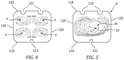
- the passages it is common for the passages to contain chevron style turbulators. These turbulators, affixed to both the upper and lower surfaces of a passage, serve to generate large scale mixing features. In particular, for the case of chevrons, a set of counter-rotating vortex pairs V is produced as seen in Fig 4 .
- the counter-rotating vortecies V move the spent fluid, near the wall, and mix it with the largely unspent fluid in the center of the passage. Additionally, the vortecies V transport this newly mixed, bulk fluid down to the surface in such a way as to enhance the convection heat transfer coefficient.
- the performance of such a turbulated passage is dependent on the temperature difference between the bulk fluid and the wall temperature.
- the set of counter-rotating vortex pairs may break down and merge together. This phenomenon has been observed most regularly when the passage is asymmetric A. As seen in Fig. 5 , when the vortecies merge M, they produce a single, larger vortex SV which transports the spend fluid around the passage without mixing it with the central, bulk flow. As a result, the temperature of the spent fluid approaches the wall temperature. The reduced temperature difference results in a significant reduction in overall heat transfer, Q.
- a vortex restart structure for a heat exchanger for a gas turbine engine comprising a second surface bounding a gas path of the gas turbine engine; a flow passage configured to deliver airflow therethrough, including: a first surface located opposite the second surface, the first surface and the second surface together defining a parting surface; a plurality of flow turbulators located along the first surface, each flow turbulator having a flow turbulator height e extending from the first surface; and the at least one vortex restart structure located along the first surface, each of at least one vortex restart structure extending from the first surface, wherein the at least one vortex restart structure is longer than the plurality of flow turbulators.
- Particular embodiments may include at least one of the following optional features. These features may be provided separately, or in combination with each other, unless specified otherwise.
- a further embodiment of any of the foregoing embodiments may additionally and/or alternatively include the flow passage includes a height H; wherein the at least one vortex restart structure extends from the first surface into the flow passage a height R; wherein 0.01 ⁇ e/H ⁇ R/H ⁇ 0.5.
- a further embodiment of any of the foregoing embodiments may additionally and/or alternatively include the plurality of flow turbulators have a pitch P; wherein the at least one vortex restart structure can be spaced apart a distance of from about 1x to about 10X the flow turbulator pitch P.
- a further embodiment of any of the foregoing embodiments may additionally and/or alternatively include a first vortex restart structure can extend from the first surface and align axially with a second vortex restart structure extending from the second surface.
- a further embodiment of any of the foregoing embodiments may additionally and/or alternatively include the parting surfaces forming the flow passage include a cross-sectional asymmetry susceptible to a vortex breakdown.
- a vortex restart structure comprising a flow passage having a first wall and a second wall opposite the first wall, each of the first wall and the second wall including a parting surface; multiple flow turbulators extending from at least one parting surface of the first wall or the second wall; and at least one vortex restart structure extending from at least one parting surface of the first wall or the second wall, wherein the at least one vortex restart structure extends from the parting surface into the flow passage beyond the multiple flow turbulators.
- Particular embodiments may include at least one of the following optional features. These features may be provided separately, or in combination with each other, unless specified otherwise.
- a further embodiment of any of the foregoing embodiments may additionally and/or alternatively include the multiple flow turbulators are formed in each of the first wall and the second wall; and the at least one vortex restart structure is formed in each of the first wall and the second wall.
- a further embodiment of any of the foregoing embodiments may additionally and/or alternatively include the multiple flow turbulators extend a distance e from the first wall and second wall respectively; wherein the flow passage includes a height H; wherein the at least one vortex restart structure extends from at least one of the first wall and the second wall into the flow passage a height R; wherein 0.01 ⁇ e/H ⁇ R/H ⁇ 0.5.
- a further embodiment of any of the foregoing embodiments may additionally and/or alternatively includethe flow passage is thermally coupled to a fluid A in communication with the parting surface of the flow passage; the parting surface configured to thermally couple fluid A and a fluid B flowing in the flow passage for the transfer of thermal energy between the fluid A and the fluid B flowing in the flow passage responsive to a formation of counter rotating vortex pairs in the fluid B being restarted.
- a further embodiment of any of the foregoing embodiments may additionally and/or alternatively include the multiple flow turbulators have a pitch P; wherein the at least one vortex restart structure configured spaced apart from about 1x to about 10X the flow turbulator pitch P.
- a further embodiment of any of the foregoing embodiments may additionally and/or alternatively include a first vortex restart structure can extend from the first wall and align axially with a second vortex restart structure extending from the second wall.
- a further embodiment of any of the foregoing embodiments may additionally and/or alternatively include the flow passage is formed in a gas turbine heat exchanger.
- a process for managing a merged vortex with a vortex restart structure for a gas turbine engine heat exchanger comprising forming a flow passage having a first wall and a second wall opposite the first wall, each of the first wall and the second wall including a parting surface; extending multiple flow turbulators from the parting surface of the first wall or the second wall; and extending at least one vortex restart structure from the parting surface of the first wall or the second wall, wherein the at least one vortex restart structure extends from the parting surface into the flow passage beyond the multiple flow turbulators.
- Particular embodiments may include at least one of the following optional features. These features may be provided separately, or in combination with each other, unless specified otherwise.
- a further embodiment of any of the foregoing embodiments may additionally and/or alternatively include the flow passage includes a height H; extending the at least one vortex restart structure from the first surface into the flow passage a height R; wherein 0.01 ⁇ e/H ⁇ R/H ⁇ 0.5.
- a further embodiment of any of the foregoing embodiments may additionally and/or alternatively include the plurality of flow turbulators have a pitch P; and spacing the at least one vortex restart structure apart a distance of from about 1x to about 10X the flow turbulator pitch P.
- a further embodiment of any of the foregoing embodiments may additionally and/or alternatively include the process further comprising extending a first vortex restart structure from the first wall; extending a second vortex restart structure from the second wall opposite the first vortex restart structure; and aligning the first vortex restart structure axially with the second vortex restart structure.
- a further embodiment of any of the foregoing embodiments may additionally and/or alternatively include the process further comprising forming the parting surfaces the flow passage including a cross-sectional asymmetry susceptible to a vortex breakdown.
- a further embodiment of any of the foregoing embodiments may additionally and/or alternatively include the process further comprising creating a physical barrier with the at least one vortex restart structure within the flow passage; and causing a merged vortex flowing in the flow passage to break up.
- a further embodiment of any of the foregoing embodiments may additionally and/or alternatively includethe process further comprising reforming a counter rotating vortex pair within a vortex restart structure zone downstream of the at least one vortex restart structure within the flow passage by use of a downstream turbulator configured to reassert influence on a flowing fluid within the flow passage.
- FIG. 1 illustrates a cast heat exchanger 10 according to one non-limiting configuration of this disclosure.
- Heat exchanger 10 has a plurality of flow passages 12 defining one flow direction A for a first heat exchange fluid A, and a second plurality of flow passages 14 defining a second flow direction B for a second heat exchange fluid B.
- Flow passages 12, 14 are defined by flow passage segments on opposite sides of a plurality of stacked heat exchanger plates 16.
- the cast heat exchanger 10 can be constructed as a set of cast plates which are then bonded together via brazing or diffusion bonding or welding.
- Fluid A may be the turbine cooling air (TCA)
- Fluid B may be air from the annular bypass duct.
- TCA turbine cooling air
- thermal energy is extracted from Fluid A, via convection, conducted through the parting surface of the heat exchanger and transferred to Fluid B, also via convection.
- the flow passage 110 can include parting surfaces 114 formed on passage walls 117.
- the parting surface 114 can thermally couple Fluid A and Fluid B for the transfer of thermal energy.
- the parting surface 114, or parting plate is the thin piece of material separating the two fluids A, B and conducts thermal energy between them.
- the flow passage 110 can be bounded by a wall 117 that can include a first wall 116 opposite a second wall 118.
- the flow passage 110 includes passage separation walls 120 apart from each other.
- the cross-sectional geometry of the flow passage 110 can be asymmetrically aligned.
- the cross-sectional asymmetry may lead to the vortex breakdown.
- the asymmetry of the parting surfaces 114 can influence counter rotating vortex pairs in the fluid, A, B flowing through the flow passage 110.
- Multiple flow turbulators 122 can be formed in each of the first wall 116 and the second wall 118.
- the flow turbulators 122 extend a distance e from the first wall 116 and second wall 118 respectively.
- the flow turbulators 122 can form a corrugated pattern.
- the flow turbulators 122 can be formed as chevron style turbulators.
- the turbulator pattern can take many forms such as chevron, discrete-V, W, discrete-W, and skewed.
- Each flow turbulator 122 has a height (e), extending from the parting surface 114 and a passage width, (W), extending along the parting surface 114. Further, adjacent flow turbulators 122 are separated by (spacing) a pitch, (P), along the stream-wise flow direction 124. The pitch, (P), is measured between centers 126 of the adjacent flow turbulator 122.
- the turbulator spacings, or Pitch, P are a function of turbulator height, e.
- the flow passage 110 may have a cross-section aspect ratio (AR) of 1 ⁇ W/H ⁇ 4. This affects the primary rib spacing. Small W/H results in many ribs, which is good for structural strength but adds weight. Large W/H spreads out the ribs, saving weight.
- typically discrete-W turbulators may be used, which have a more complex vortex pattern.
- Each flow turbulator 122 can have an e/H of about 0.01 to about 0.3. A low e/H is a less aggressive turbulator, with a low heat transfer coefficient but low pressure loss. A high e/H is just the opposite with a high heat transfer coefficient but high pressure loss.
- the turbulator 122 produces a pair of counter rotating vortices V which mix the spent, near wall gas with bulk, or central fluid.
- the mixing results in a higher temperature differential between the fluid 112 and walls 116, 118, producing high heat transfer.
- counter rotating vortex pairs V found in chevron based, turbulated passages may break down under certain flow passage geometry causing the corner vortices to merge M, resulting the single vortex SV and in reduced heat transfer with little gas mixing near the walls, as seen in Fig. 5 .
- At least one vortex restart structure or splash rib 128 is formed in the flow passage 110.
- the splash rib 128 extends into the flow path of passage 110 from at least one of the first wall 116, and the second wall 118 into the flow passage 110, a height R.
- the splash rib 128 can have a height 0.01 ⁇ e/H ⁇ R/H ⁇ 0.5.
- the splash rib 128 height and other dimensions may be tailored to a particular flow passage 110 based on the fluid 112 conditions and flow passage 110 geometry.
- the splash rib 128 does not extend to the centerline CL but instead can extend short of the centerline CL to avoid contacting the adjacent splash rib 128, thus avoiding any structural response. This prevents transmission of structural loads between adjacent splash ribs 128.
- the splash rib 128 can have a length (along flow direction 124) of 2X the flow turbulator pitch P.
- the splash rib 128 can be spaced apart from about 1x to about 3X the flow turbulator pitch P.
- the axial length of the splash rib 128 can be configured to influence the bulk flow. A multiple of the turbulator pitch is convenient because it allows for easy blending with the turbulator structures 122.
- the splash rib 128 can overlap with the flow turbulator 122, to avoid any stress risers.
- the splash rib 128 can be spaced apart at the most every 10 flow turbulators 122.
- the splash rib 128 can be spaced apart at other distances closer or further, depending on needs of the design and the flow conditions in the flow passage 110.
- the splash rib 128 extending from the first wall 116 can align axially with the splash rib 128 extending from the second wall 118.
- the splash rib 128 can be a short, partial height rib structure which creates a physical barrier into which the undesirable, merged vortex can "splash" into causing the merged vortex to break up.
- the local flow turbulators 122 can reassert influence on the flowing cooling fluid 112 to reform a counter rotating vortex pair.
- a particular flow passage 110 configuration (inclusive of a particular flow turbulator/splash rib configuration) that is used may be based on one or more tests, simulations, computational fluid dynamics (CFD) analyses, and the like.
- CFD computational fluid dynamics
- the heat exchanger may be used for internal engine cooling purposes (e.g., cooling a compressed bleed flow bled from the compressor and directing it to cool the turbine).
- Alternative cooling involves similarly drawing bleed air but directing it to elsewhere in the aircraft.
- a single heat exchanger may serve both purposes (with outlet flow split) or there may be multiple such heat exchangers each with a dedicated purpose.
- Yet another purpose involves non-bleed flows. For example, there may be in-aircraft cooling requirements wherein a flow from the aircraft fuselage is passed to the heat exchanger inlet and returned via the outlet (e.g., a closed-loop system).
- Various components of this disclosure may be composed of one or more materials.
- one or more metals e.g., nickel, steel, aluminum, titanium, etc.
- one or more metals may be used in a manufacture of the heat exchanger.
- One or more techniques may be utilized to manufacture a heat exchanger of this disclosure. For example, casting, machining, an application of one or more chemicals (e.g., chemical etching), additive manufacturing, etc., may be used.
- one or more chemicals e.g., chemical etching
- additive manufacturing etc.
- flow passage can also be formed as part of other gas turbine components, such as vanes, blades and blade outer air seals.
- a technical advantage of the disclosed vortex restart structure includes a 10% higher integrated heat flux by employing the splash ribs as compared to not employing the splash ribs.
- Another technical advantage of the disclosed vortex restart structure includes merely a slight increase in overall pressure loss by utilizing the splash ribs.
- first, second, and the like in the following claims is for differentiation within the claim only and does not necessarily indicate relative or absolute importance or temporal order. Similarly, the identification in a claim of one element as “first” (or the like) does not preclude such "first” element from identifying an element that is referred to as “second” (or the like) in another claim or in the description.
Landscapes
- Engineering & Computer Science (AREA)
- Mechanical Engineering (AREA)
- General Engineering & Computer Science (AREA)
- Chemical & Material Sciences (AREA)
- Combustion & Propulsion (AREA)
- Physics & Mathematics (AREA)
- Thermal Sciences (AREA)
- Turbine Rotor Nozzle Sealing (AREA)
Applications Claiming Priority (1)
| Application Number | Priority Date | Filing Date | Title |
|---|---|---|---|
| US18/138,366 US12129796B1 (en) | 2023-04-24 | 2023-04-24 | Vortex restart structures for turbulated passages |
Publications (1)
| Publication Number | Publication Date |
|---|---|
| EP4455456A1 true EP4455456A1 (de) | 2024-10-30 |
Family
ID=90057345
Family Applications (1)
| Application Number | Title | Priority Date | Filing Date |
|---|---|---|---|
| EP24159298.9A Pending EP4455456A1 (de) | 2023-04-24 | 2024-02-23 | Wirbelneustartstruktur für wirbelkanäle |
Country Status (2)
| Country | Link |
|---|---|
| US (1) | US12129796B1 (de) |
| EP (1) | EP4455456A1 (de) |
Citations (6)
| Publication number | Priority date | Publication date | Assignee | Title |
|---|---|---|---|---|
| DE3739619A1 (de) * | 1987-11-23 | 1988-04-07 | Martin Prof Dr Ing Fiebig | Tuetenwirbelgeneratoren und waermeuebertragungsflaechen fuer waermeaustauscher |
| DE10127084A1 (de) * | 2000-06-17 | 2002-03-28 | Behr Gmbh & Co | Wärmeübertrager, insbesondere für Kraftfahrzeuge |
| DE202004013882U1 (de) * | 2004-09-03 | 2006-01-12 | Autokühler GmbH & Co. KG | Wärmeübertragungsbauteil und damit hergestellter Wärmeaustauscher |
| DE202004020294U1 (de) * | 2004-12-29 | 2006-05-11 | Autokühler GmbH & Co. KG | Wärmeaustauschelement und damit hergestellter Wärmeaustauscher |
| WO2010110833A2 (en) * | 2008-12-31 | 2010-09-30 | Frontline Aerospace, Inc. | Recuperator for gas turbine engines |
| EP2397457A2 (de) * | 2006-03-23 | 2011-12-21 | Velocys Inc. | Verfahren zur Herstellung von Styrol mittels Mikrokanaltechnik |
Family Cites Families (2)
| Publication number | Priority date | Publication date | Assignee | Title |
|---|---|---|---|---|
| DE502004008210D1 (de) | 2004-07-26 | 2008-11-20 | Siemens Ag | Gekühltes Bauteil einer Strömungsmaschine und Verfahren zum Giessen dieses gekühlten Bauteils |
| US10364684B2 (en) * | 2014-05-29 | 2019-07-30 | General Electric Company | Fastback vorticor pin |
-
2023
- 2023-04-24 US US18/138,366 patent/US12129796B1/en active Active
-
2024
- 2024-02-23 EP EP24159298.9A patent/EP4455456A1/de active Pending
Patent Citations (6)
| Publication number | Priority date | Publication date | Assignee | Title |
|---|---|---|---|---|
| DE3739619A1 (de) * | 1987-11-23 | 1988-04-07 | Martin Prof Dr Ing Fiebig | Tuetenwirbelgeneratoren und waermeuebertragungsflaechen fuer waermeaustauscher |
| DE10127084A1 (de) * | 2000-06-17 | 2002-03-28 | Behr Gmbh & Co | Wärmeübertrager, insbesondere für Kraftfahrzeuge |
| DE202004013882U1 (de) * | 2004-09-03 | 2006-01-12 | Autokühler GmbH & Co. KG | Wärmeübertragungsbauteil und damit hergestellter Wärmeaustauscher |
| DE202004020294U1 (de) * | 2004-12-29 | 2006-05-11 | Autokühler GmbH & Co. KG | Wärmeaustauschelement und damit hergestellter Wärmeaustauscher |
| EP2397457A2 (de) * | 2006-03-23 | 2011-12-21 | Velocys Inc. | Verfahren zur Herstellung von Styrol mittels Mikrokanaltechnik |
| WO2010110833A2 (en) * | 2008-12-31 | 2010-09-30 | Frontline Aerospace, Inc. | Recuperator for gas turbine engines |
Also Published As
| Publication number | Publication date |
|---|---|
| US20240352888A1 (en) | 2024-10-24 |
| US12129796B1 (en) | 2024-10-29 |
Similar Documents
| Publication | Publication Date | Title |
|---|---|---|
| US5797726A (en) | Turbulator configuration for cooling passages or rotor blade in a gas turbine engine | |
| US9051943B2 (en) | Gas turbine engine heat exchanger fins with periodic gaps | |
| US10260523B2 (en) | Fluid cooling system integrated with outlet guide vane | |
| US8876475B1 (en) | Turbine blade with radial cooling passage having continuous discrete turbulence air mixers | |
| EP3553446B1 (de) | Geformte vorderkante eines gussplatten-rippenwärmetauschers | |
| CN110892140B (zh) | 包括气液热交换器的飞行器推进组件 | |
| CN106959034A (zh) | 用于嵌入式发动机应用的热交换器 | |
| EP3196585A1 (de) | Wärmetauscher mit mittelverteiler | |
| US9587494B2 (en) | Gas turbine, gas turbine blade, and manufacturing method of gas turbine blade | |
| US9163518B2 (en) | Full coverage trailing edge microcircuit with alternating converging exits | |
| US7137784B2 (en) | Thermally loaded component | |
| US20150204615A1 (en) | Dendritic Tube Circular Fin Heat Exchanger | |
| EP3176533B1 (de) | Querstromkeramikwärmetauscher und verfahren zur herstellung | |
| US12129796B1 (en) | Vortex restart structures for turbulated passages | |
| EP1561903B1 (de) | Geschneiderte Wirbelbildung für Turbinenschaufeln | |
| EP3584407B1 (de) | Kühlrippen für erweiterte grenzschichtmischung | |
| EP3196581B1 (de) | Wärmetauscher mit mittelverteiler und wärmeseparator | |
| GB2700263A (en) | Interwoven heat exchanger core with end face features | |
| US20250035387A1 (en) | Heat exchanger | |
| EP3553448B1 (de) | Sekundär angewendetes kaltseitenfeatures für gegossenen wärmetauscher | |
| US11187470B2 (en) | Plate fin crossflow heat exchanger | |
| EP3375978B1 (de) | Filmgekühlte turbinenschaufel | |
| CN118742718A (zh) | 空气-油热交换器 | |
| Shevchenko et al. | Numerical and Experimental Study of the Actual Rib Geometry Influence on Heat Transfer in the Gas Turbine Blade Cooling Channels |
Legal Events
| Date | Code | Title | Description |
|---|---|---|---|
| PUAI | Public reference made under article 153(3) epc to a published international application that has entered the european phase |
Free format text: ORIGINAL CODE: 0009012 |
|
| STAA | Information on the status of an ep patent application or granted ep patent |
Free format text: STATUS: THE APPLICATION HAS BEEN PUBLISHED |
|
| AK | Designated contracting states |
Kind code of ref document: A1 Designated state(s): AL AT BE BG CH CY CZ DE DK EE ES FI FR GB GR HR HU IE IS IT LI LT LU LV MC ME MK MT NL NO PL PT RO RS SE SI SK SM TR |
|
| STAA | Information on the status of an ep patent application or granted ep patent |
Free format text: STATUS: REQUEST FOR EXAMINATION WAS MADE |
|
| 17P | Request for examination filed |
Effective date: 20250311 |