EP4456686A1 - Ensemble rail coulissant - Google Patents
Ensemble rail coulissant Download PDFInfo
- Publication number
- EP4456686A1 EP4456686A1 EP24162589.6A EP24162589A EP4456686A1 EP 4456686 A1 EP4456686 A1 EP 4456686A1 EP 24162589 A EP24162589 A EP 24162589A EP 4456686 A1 EP4456686 A1 EP 4456686A1
- Authority
- EP
- European Patent Office
- Prior art keywords
- rail
- state
- blocking member
- assisting
- slide rail
- Prior art date
- Legal status (The legal status is an assumption and is not a legal conclusion. Google has not performed a legal analysis and makes no representation as to the accuracy of the status listed.)
- Pending
Links
Images








Classifications
-
- H—ELECTRICITY
- H05—ELECTRIC TECHNIQUES NOT OTHERWISE PROVIDED FOR
- H05K—PRINTED CIRCUITS; CASINGS OR CONSTRUCTIONAL DETAILS OF ELECTRIC APPARATUS; MANUFACTURE OF ASSEMBLAGES OF ELECTRICAL COMPONENTS
- H05K7/00—Constructional details common to different types of electric apparatus
- H05K7/14—Mounting supporting structure in casing or on frame or rack
- H05K7/1485—Servers; Data center rooms, e.g. 19-inch computer racks
- H05K7/1488—Cabinets therefor, e.g. chassis or racks or mechanical interfaces between blades and support structures
- H05K7/1489—Cabinets therefor, e.g. chassis or racks or mechanical interfaces between blades and support structures characterized by the mounting of blades therein, e.g. brackets, rails, trays
-
- A—HUMAN NECESSITIES
- A47—FURNITURE; DOMESTIC ARTICLES OR APPLIANCES; COFFEE MILLS; SPICE MILLS; SUCTION CLEANERS IN GENERAL
- A47B—TABLES; DESKS; OFFICE FURNITURE; CABINETS; DRAWERS; GENERAL DETAILS OF FURNITURE
- A47B88/00—Drawers for tables, cabinets or like furniture; Guides for drawers
- A47B88/50—Safety devices or the like for drawers
- A47B88/57—Safety devices or the like for drawers preventing complete withdrawal of the drawer
-
- A—HUMAN NECESSITIES
- A47—FURNITURE; DOMESTIC ARTICLES OR APPLIANCES; COFFEE MILLS; SPICE MILLS; SUCTION CLEANERS IN GENERAL
- A47B—TABLES; DESKS; OFFICE FURNITURE; CABINETS; DRAWERS; GENERAL DETAILS OF FURNITURE
- A47B88/00—Drawers for tables, cabinets or like furniture; Guides for drawers
- A47B88/40—Sliding drawers; Slides or guides therefor
- A47B88/423—Fastening devices for slides or guides
- A47B2088/4235—Fastening devices for slides or guides having a latch mechanism coupling or disconnecting a drawer with drawer side slide from the rest of the slide members
Definitions
- U.S. Patent No. 8,210,623 B2 it discloses a damping device adapted for a slide rail assembly having a first rail and a second rail slidable relative to the first rail.
- the damping device includes a first supporting frame, a second supporting frame, a rack and a damper.
- the first supporting frame is fixedly mounted on the first rail.
- the second supporting frame is fixedly mounted on the second rail.
- the rack is mounted on the first supporting frame.
- the damper is mounted on the second supporting frame.
- the damper includes a container and a gear pivotally connected to the container.
- a damping material e.g., thick and sticky liquid, is received inside the container.
- the gear of the damper is driven by the rack to rotatably cooperate with the damping material received inside the container, so as to generate a constant damping force for resisting a movement of the second rail relative to the first rail.
- the present invention aims at providing a slide rail assembly having a blocking mechanism capable of positioning a second rail relative to a first rail at different positions.
- the claimed slide rail assembly includes a first rail, a second rail, a plurality of assisting structures, a blocking member and an operating member.
- the second rail is longitudinally displaceable relative to the first rail along a first direction or a second direction opposite to the first direction and between a retracted position and an extended position.
- the plurality of assisting structures are arranged on the first rail. Adjacent two of the plurality of assisting structures are spaced from each other.
- the blocking member is movably mounted on the second rail.
- the operating member is movably mounted on the second rail. The operating member is configured to operate the blocking member to move from a first state to a second state.
- the blocking member in the first state is configured to block one of the plurality of assisting structures for preventing the second rail from displacing from a predetermined position along the second direction.
- the operating member is configured to operate the blocking member to move from the first state to the second state, such that the blocking member does not block the one of the plurality of assisting structures for allowing the second rail to displace to the retracted position along the second direction.
- Each of the plurality of assisting structures is configured to drive the blocking member to move away from the first state for allowing the blocking member to pass over a corresponding one of the plurality of assisting structures when the second rail displaces along the first direction.
- a slide rail assembly 20 includes a first rail 22 and a second rail 24 displaceable relative to the first rail 22 longitudinally.
- a first positioning structure 26, at least one assisting structure and a second positioning structure 30 are arranged on the first rail 22.
- the at least one assisting structure is located between the first positioning structure 26 and the second positioning structure 30.
- the present invention is not limited to this embodiment. It depends on practical demands.
- the first positioning structure 26 and the second positioning structure 30 can have substantially identical structures, and the first assisting structure 28a, the second assisting structure 28b, the third assisting structure 28c and the fourth assisting structure 28d can have substantially identical structures.
- the first positioning structure 26, the first assisting structure 28a, the second assisting structure 28b, the third assisting structure 28c, the fourth assisting structure 28d and the second positioning structure 30 can be arranged sequentially along a longitudinal direction at equal intervals X.
- adjacent two of the first positioning structure 26, the first assisting structure 28a, the second assisting structure 28b, the third assisting structure 28c, the fourth assisting structure 28d and the second positioning structure 30 can be spaced from each other by a predetermined longitudinal distance.
- the present invention is not limited to this embodiment.
- the first positioning structure, the first assisting structure, the second assisting structure, the third assisting structure, the fourth assisting structure and the second positioning structure can be sequentially arranged along the longitudinal direction at unequal intervals.
- the first positioning structure 26, the first assisting structure 28a, the second assisting structure 28b, the third assisting structure 28c, the fourth assisting structure 28d and the second positioning structure 30 can be arranged onto the first rail 22 directly or indirectly.
- the first positioning structure 26, the first assisting structure 28a, the second assisting structure 28b, the third assisting structure 28c, the fourth assisting structure 28d and the second positioning structure 30 can be protrusions.
- the slide rail assembly 20 further includes a releasing member 32 movably mounted on the second rail 24, a blocking member 34 movably mounted on the second rail 24 and an operating member 36 movably mounted on the second rail 24.
- the blocking member 34 and the releasing member 32 can be pivotally connected to the second rail 24 by a first shaft 40 and a second shaft 38, respectively.
- the operating member 36 is configured to operate the releasing member 32 and the blocking member 34.
- the releasing member 32 can be configured to allow or restrain a displacement of the second rail 24 relative to the first rail 22 along a first direction D1
- the blocking member 34 can configured to allow or restrain a displacement of the second rail 24 relative to the first rail 22 along a second direction D2.
- the slide rail assembly can include the blocking member and the operating member configured to operate the blocking member only, i.e., the releasing member can be omitted, when it is only desired to restrain the displacement of the second rail 24 relative to the first rail 22 along the second direction D2.
- the slide rail assembly 20 further includes a first resilient portion 44 and a second resilient portion 42 configured to resiliently retain the blocking member 34 and the releasing member 32 in a first state S1, respectively.
- the first resilient portion 44 and the second resilient portion 42 can be resilient arms or resilient legs integrally connected to the blocking member 34 and the releasing member 32 respectively, wherein a first predetermined gap G1 can be formed between the second resilient portion 42 and the releasing member 32, and a second predetermined gap G2 can be formed between the first resilient portion 44 and the blocking member 34.
- the present invention is not limited to this embodiment.
- each of the first predetermined portion 48 and the second predetermined portion 46 can be a hole or a slot
- each of the first resilient portion 44 and the second resilient portion 42 can include a bending section inserted into a corresponding one of the first predetermined portion 48 and the second predetermined portion 46 and abutted by a wall of the corresponding one of the first predetermined portion 48 and the second predetermined portion 46.
- the present invention is not limited to this embodiment.
- each of the first predetermined portion and the second predetermined portion can be a wall or a protruding portion.
- the slide rail assembly 20 further includes a recovering resilient member 50 configured to provide a recovering resilient force F' to the operating member 36.
- each of the first positioning structure 26, the first assisting structure 28a, the second assisting structure 28b, the third assisting structure 28c, the fourth assisting structure 28d and the second positioning structure 30 includes two opposite ends, e.g., a first end E1 and a second end E2.
- a blocking structure can be arranged on each of the first end E1 and the second end E2 of the first positioning structure 26 and the first end E1 and the second end E2 of the second positioning structure 30, wherein the blocking structure can be a blocking wall or a vertical wall.
- a guiding section M can be arranged adjacent to the first end E1 of each of the first assisting structure 28a, the second assisting structure 28b, the third assisting structure 28c and the fourth assisting structure 28d, and a blocking section can be arranged on the second end E2 of each of the first assisting structure 28a, the second assisting structure 28b, the third assisting structure 28c and the fourth assisting structure 28d, wherein the guiding section M can be an inclined surface or an arc surface, and the blocking section can be a blocking wall or a vertical wall.
- the first rail 22 includes a front end portion 22a and a rear end portion 22b.
- the second rail 24 includes a front end portion 24a and a rear end portion 24b.
- the first positioning structure 26 is located adjacent to the rear end portion 22b of the first rail 22.
- the second positioning structure 30 is located adjacent to the front end portion 22a of the first rail 22.
- the first rail 22 further includes a channel 29 for receiving the second rail 24. Furthermore, the first positioning structure 26, the first assisting structure 28a, the second assisting structure 28b, the third assisting structure 28c, the fourth assisting structure 28d and the second positioning structure 30 are located inside the channel 29 of the first rail 22.
- the releasing member 32 and the blocking member 34 are located adjacent to the rear end portion 24b of the second rail 24.
- the operating member 36 includes an operating portion 52, a driving portion 54 and an extending portion 56 connected between the operating portion 52 and the driving portion 54.
- the operating portion 52 is located adjacent to the front end portion 24a of the second rail 24.
- the driving portion 54 can include a first driving section 58 and a second driving section 60 configured to drive the releasing member 32 and the blocking member 34, respectively.
- the extending portion 56 can extend along a length direction of the second rail 24, i.e., the longitudinal direction.
- the operating member is configured to operate the releasing member or the blocking member only, e.g., the driving portion can include one of the first driving section and the second driving section for driving a corresponding one of the releasing member and the blocking member, when the blocking member is configured to drive the releasing member to move together with the blocking member or the releasing member is configured to drive the blocking member to move together with the releasing member.
- the releasing member 32 and the blocking member 34 can be made of non-metallic material, e.g., plastic material.
- the present invention is not limited to this embodiment.
- a space J is defined between the releasing member 32 and the blocking member 34 and configured to receive one of the first positioning structure 26, the first assisting structure 28a, the second assisting structure 28b, the third assisting structure 28c and the fourth assisting structure 28d and the second positioning structure 30.
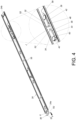
- the operating member 36 is configured to operate the releasing member 32 and the blocking member 34 to move from the first state S1 as shown in FIG. 3 to a second state S2 as shown in FIG. 4 .
- the operating portion 52 of the operating member 36 is applied by a force F to drive the operating member 36 to move from a first operating position K1 as shown in FIG. 3 to a second operating position K2 as shown in FIG.
- the first driving section 58 and the second driving section 60 of the operating member 36 drive the releasing member 32 and the blocking member 34 to pivot from the first state S1 as shown in FIG. 3 to the second state S2 as shown in FIG. 4 respectively, such that the recovering resilient member 50 is resiliently deformed by the operating member 36, and the first resilient portion 44 and the second resilient portion 42 are resiliently deformed by the first predetermined portion 48 and the second predetermined portion 46 of the second rail 24 respectively.
- the operating portion 52 of the operating member 36 is released from the force F, the operating member 36 recovers from the second operating position K2 as shown in FIG. 4 to the first operating position K1 as shown in FIG.
- the first rail 22 can be vertically mounted on an object, which is not shown in the figure.
- the rear end portion 22b of the first rail 22 can face downwardly, e.g., toward a ground surface, and the front end portion 22a of the first rail 22 can face upwardly.
- the front end portion 22a of the first rail 22 can face upwardly.
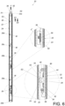
- the slide rail assembly 20 when the second rail 24 is located at a first predetermined position P1, e.g., a retracted position, relative to the first rail 22, the slide rail assembly 20 has a first length L1, and the releasing member 32 in the first state S1 and the blocking member 34 in the first state S 1 block the first end E1 and the second end E2 of the first positioning structure 26 respectively to generate a bidirectional blocking effect for preventing the second rail 24 from displacing from the first predetermined position P1 along the first direction D1, e.g., an opening direction, or the second direction D2, e.g., a retracting direction.
- a first predetermined position P1 e.g., a retracted position
- the slide rail assembly 20 has a first length L1
- the releasing member 32 in the first state S1 and the blocking member 34 in the first state S 1 block the first end E1 and the second end E2 of the first positioning structure 26 respectively to generate a bidirectional blocking effect for preventing the second rail 24 from displac
- the operating member 36 is retained at the first operating position K1 in response to the recovering resilient force F' provided by the recovering resilient member 50.
- the operating member 36 further includes an extending section 62 located at a position corresponding to the resilient recovering member 50.
- the first driving section 58 and the second driving section 60 of the operating member 36 drive the releasing member 32 and the blocking member 34 to pivot from the first state S1 as shown in FIG. 5 to the second state S2 as shown in FIG.
- the recovering resilient member 50 is resiliently deformed by the extending section 62 of the operating member 36, and the first resilient portion 44 and the second resilient portion 42 are resiliently deformed by the first predetermined portion 48 and the second predetermined portion 46, respectively.
- the releasing member 32 and the blocking member 34 can recover back to the first state S1 in response to the resilient forces provided by the second resilient portion 42 and the first resilient portion 44, respectively.
- the releasing member 32 and the blocking member 34 can pass over the first assisting structure 28a, the second assisting structure 28b, the third assisting structure 28c and the fourth assisting structure 28d until the releasing member 32 and the blocking member 34 are located at positions corresponding to the first end E1 and the second end E2 of the second positioning structure 30, respectively.
- each of the guiding section M facilitates the releasing member 32 and the blocking member 34 to pass over a corresponding one of the first assisting structure 28a, the second assisting structure 28b, the third assisting structure 28c and the fourth assisting structure 28d.
- the blocking member 34 in the first state S 1 can block the second end E2 of the second assisting structure 28b for preventing the second rail 24 from displacing from the second predetermined position P2 along the second direction D2.
- the slide rail assembly 20 has a second length L2.
- the second rail 24 when the second rail 24 is displaced from the first predetermined position P1 to the second predetermined position P2 along the first direction D1 and the operating member 36 is released from the force F for recovering the operating member 36 from the second operating position K2 back to the first operating position K1, the releasing member 32 and the blocking member 34 recover from the second state S2 back to the first state S 1, such that the blocking member 34 in the first state S1 blocks the second end E2 of the second assisting structure 28b to generate a unidirectional blocking effect for preventing the second rail 24 from displacing from the second predetermined position P2 along the second direction D2. It should be noticed that, as shown in FIG. 7 , at this moment, the second rail 24 is allowed to displace from the second predetermined position P2 along the second direction D2 only when the operating member 36 is operated to drive the blocking member 34 to pivot from the first state S 1 to the second state S2.
- the second rail 24 when the second rail 24 is located at the second predetermined position P2, the second rail 24 is still allowed to displace from the second predetermined position P2 along the first direction D1 due to the unidirectional blocking effect.
- the releasing member 32 can be abutted by the guiding section M of the second assisting structure 28b to pivot and resiliently deform the second resilient portion 42, so as to pass over the second assisting structure 28b.
- the releasing member 32 can be retained in the first state S1 in response to the resilient force provided by the second resilient portion 42, and the blocking member 34 in the first state S1 can be abutted by the guiding section M of the third assisting structure 28c to pivot and resiliently deform the first resilient portion 44, so as to pass over the third assisting structure 28c.
- the blocking member 34 in the first state S1 can block the second end E2 of the third assisting structure 28c to generate the unidirectional blocking effect for preventing the second rail 24 from displacing from the another predetermined position as shown in FIG. 10 along the second direction D2. It should be noticed that, as shown in FIG. 10 , at this moment, the second rail 24 is allowed to displace from the another predetermined position along the second direction D2 only when the operating member 36 is operated to drive the blocking member 34 to pivot from the first state S1 to the second state S2.
- the blocking member 34 includes a guiding portion 63.
- the guiding portion 63 can be an inclined surface or an arc surface.
- the guiding portion 63 of the blocking member 34 in the first state S1 can be abutted by the second positioning structure 30 to drive the blocking member 34 to pivot and resiliently deform the first resilient portion 44, so as to pass over the first end E1 of the second positioning structure 30.
- the blocking member 34 can recover back to the first state S1 in response to the resilient force provided by the first resilient portion 44, so as to block the second end E2 of the second positioning structure 30 for preventing the second rail 24 from displacing from the third predetermined position P3 along the second direction D2. Furthermore, as shown in FIG. 13 , when the second rail 24 is located at the third predetermined position P3 relative to the first rail 22, the releasing member 32 is in the first state S1 and blocks the first end E1 of the second positioning structure 30 for preventing the second rail 24 from displacing from the third predetermined position P3 along the first direction D 1.
- the slide rail assembly 20 has a third length L3.
- the third length L3 is greater than the second length L2.
- the second length L2 is greater than the first length L1.
- the releasing member 32 in the second state S2 and the blocking member 34 in the second state S2 do not block the first end E1 and the second end E2 of the second positioning structure 30 respectively, so as to allow the second rail 24 to displace from the third predetermined position P3 along the first direction D1 or along the second direction D2, e.g., for allowing a detaching movement or a retracting movement of the second rail 24 relative to the first rail 22.
- the operating portion 52 of the operating member 36 can be applied by the force F to drive the operating member 36 to move from the first operating position K1 to the second operating position K2 for driving the releasing member 32 and the blocking member 34 to move from the first state S1 to the second state S2 respectively, such that the releasing member 32 and the blocking member 34 do not block the first end E1 and the second end E2 of the second positioning structure 30 respectively, so as to allow the second rail 24 to displace from the third predetermined position P3 along the first direction D1 or along the second direction D2, e.g., for allowing the detaching movement or the retracting movement of the second rail 24 relative to the first rail 22.
- the blocking member 34 in the first state S1 is configured to block the second end E2 of one of the first assisting structure 28a, the second assisting structure 28b, the third assisting structure 28c and the fourth assisting structure 28d to generate the unidirectional blocking effect.
- the operating member 36 has to be applied by the force F to drive the blocking member 34 to move from the first state S1 to the second state S2, such that the blocking member 34 in the second state S2 does not block the second end E2 of one of the first assisting structure 28a, the second assisting structure 28b, the third assisting structure 28c and the fourth assisting structure 28d for allowing the second rail 24 to displace to the first predetermined position P1 as shown in FIG. 5 , e.g., the retracted position, along the second direction D2.
- the first predetermined position P1 as shown in FIG. 5
- the retracted position e.g., the retracted position
- the releasing member 32 in the first state S1 and the blocking member 34 in the first state S1 block the first end E1 and the second end E2 of the first positioning structure 26 respectively to generate the bidirectional blocking effect for preventing the second rail 24 from displacing from the first predetermined position P1 along the first direction D1 or the second direction D2.
- the releasing member 32 includes a guiding feature 64 which can be an inclined surface or an arc surface.
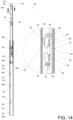
- the second rail 24 is displaced from the third predetermined position P3, e.g., to the position as shown in FIG. 15 , along the second direction D2 and the operating member 36 is released from the force F for recovering the operating member 36 back to the first operating position K1, the releasing member 32 and the blocking member 34 can recover back to the first state S1.
- the second rail 24 is displaced from the third predetermined position P3, e.g., to the position as shown in FIG. 15 , along the second direction D2 and the operating member 36 is released from the force F for recovering the operating member 36 back to the first operating position K1
- the releasing member 32 and the blocking member 34 can recover back to the first state S1.
- the guiding feature 64 of the releasing member 32 can be abutted by the fourth assisting structure 28d to pivot the releasing member 32 to pass over the second end E2 of the fourth assisting structure 28d.
- the blocking member 34 in the first state S 1 blocks the second end E2 of the fourth assisting structure 28d to generate the unidirectional blocking effect for preventing the second rail 24 from displacing from the fourth predetermined position P4 along the second direction D2.
- the operating member 36 has to be applied by the force F to drive the blocking member 34 to move from the first state S 1 to the second state S2, such that the blocking member 34 does not block the second end E2 of the fourth assisting structure 28d for allowing the second rail 24 to displace from the fourth predetermined position P4 toward the first predetermined position P1 along the second direction D2.
- the operating member 36 has to be applied by the force F to drive the blocking member 34 to move from the first state S 1 to the second state S2, such that the blocking member 34 does not block the second end E2 of the second assisting structure 28b for allowing the second rail 24 to displace from the second predetermined position P2 toward the first predetermined position P1 along the second direction D2.
- the blocking member 34 in the first state S 1 can block the second end E2 of one of the first assisting structure 28a, the second assisting structure 28b, the third assisting structure 28c and the fourth assisting structure 28d for preventing a nonstop direct displacement of the second rail 24 from the third predetermined position P3, e.g., the extended position, to the first predetermined position P1, e.g., the retracted position, along the second direction D2.
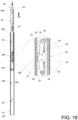
- the slide rail assembly 20 is adapted for a first object 66 and a second object 68.
- the first object 66 includes a receiving space 70 for receiving liquid, which is illustrated by dots.
- the second object 68 can be a carried object, e.g., a chassis.
- the slide rail assembly 20 is arranged in the vertical state.
- the rear end portion 22b of the first rail 22 faces downwardly, e.g., toward a bottom portion B of the first object 66.
- the front end portion 22a of the first rail 22 faces upwardly.
- the first rail 22 is mounted or fixed on the first object 66 and located inside the receiving space 70.
- the second rail 24 is configured to support the second object 68.
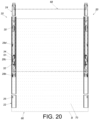
- the second object 68 can be positioned at different positions relative to the first object 66 by the slide rail assembly 20. For example, as shown in FIG. 19 , when the second rail 24 is located at the third predetermined position P3, e.g., the extended position, relative to the first rail 22, the second object 68 can be positioned at a highest using position relative to first object 66. At this moment, the operating member 36 can be operated to drive the blocking member 34, such that the blocking member 34 does not block the second end E2 of the second positioning structure 30 for allowing the second rail 24 to displace along the second direction D2, so as to lower the second object 68 relative to the first object 66.
- the blocking member 34 in the first state S 1 can block one of the first assisting structure 28a, the second assisting structure 28b, the third assisting structure 28c and the fourth assisting structure 28d for preventing the nonstop direct displacement of the second rail 24 from the third predetermined position P3 to the first predetermined position P1 due to gravity, which prevents a collision damage of the second object 68.
- the present invention is not limited to the aforementioned embodiment.
- the first positioning structure and the second positioning structure can be replaced by a fifth assisting structure and a sixth assisting structure respectively, and the releasing member can be omitted, wherein the each of the fifth assisting structure and the sixth assisting structure can be identical to the first assisting structure, the second assisting structure, the third assisting structure and the fourth assisting structure, such that the second object is displaceable relative to the first object along the first direction from the first predetermined position to the third predetermined position without operation of the operating member, and the second object can be supported at different positions by a one-way blocking effect generated by a blocking relation of the blocking member and the second end of the corresponding assisting structure.
- the slide rail assembly 20 includes the following characteristics:
Landscapes
- Engineering & Computer Science (AREA)
- General Engineering & Computer Science (AREA)
- Computer Hardware Design (AREA)
- Microelectronics & Electronic Packaging (AREA)
- Bearings For Parts Moving Linearly (AREA)
- Drawers Of Furniture (AREA)
- Mechanical Engineering (AREA)
Applications Claiming Priority (1)
| Application Number | Priority Date | Filing Date | Title |
|---|---|---|---|
| TW112114466A TWI826306B (zh) | 2023-04-17 | 2023-04-17 | 滑軌總成 |
Publications (1)
| Publication Number | Publication Date |
|---|---|
| EP4456686A1 true EP4456686A1 (fr) | 2024-10-30 |
Family
ID=90053427
Family Applications (1)
| Application Number | Title | Priority Date | Filing Date |
|---|---|---|---|
| EP24162589.6A Pending EP4456686A1 (fr) | 2023-04-17 | 2024-03-11 | Ensemble rail coulissant |
Country Status (4)
| Country | Link |
|---|---|
| US (1) | US12419417B2 (fr) |
| EP (1) | EP4456686A1 (fr) |
| JP (1) | JP2024153544A (fr) |
| TW (1) | TWI826306B (fr) |
Families Citing this family (1)
| Publication number | Priority date | Publication date | Assignee | Title |
|---|---|---|---|---|
| TWI884007B (zh) * | 2024-06-19 | 2025-05-11 | 川湖科技股份有限公司 | 滑軌總成 |
Citations (4)
| Publication number | Priority date | Publication date | Assignee | Title |
|---|---|---|---|---|
| US8210623B2 (en) | 2010-01-29 | 2012-07-03 | King Slide Works Co., Ltd. | Sliding assembly with damping device |
| CN102724844A (zh) * | 2012-06-27 | 2012-10-10 | 浙江中控西子科技有限公司 | 一种限位器 |
| US20130105427A1 (en) * | 2011-10-28 | 2013-05-02 | Fujitsu Technology Solutions Intellectual Property Gmbh | Universal carrier for mounting on vertical support profiles of a rack and arrangement with such a universal carrier and vertical support profiles of a rack |
| US20190200756A1 (en) * | 2017-12-28 | 2019-07-04 | King Slide Works Co., Ltd. | Slide rail assembly and rail kit thereof |
Family Cites Families (9)
| Publication number | Priority date | Publication date | Assignee | Title |
|---|---|---|---|---|
| JPH0428307A (ja) | 1990-05-23 | 1992-01-30 | Sugatsune Ind Co Ltd | 部材の走行制御装置 |
| JPH10108736A (ja) * | 1996-10-08 | 1998-04-28 | Omuni Techno Kk | 高さが調整できる脇机、ワゴンテーブル等 |
| US6367899B1 (en) * | 2001-09-28 | 2002-04-09 | King Slide Works Co., Ltd. | Forward pull type bolt lock structure of a slide |
| US6935710B2 (en) * | 2003-03-05 | 2005-08-30 | King Slide Works Co., Ltd. | Two-way retainer for a slide track assembly of drawers |
| US6824233B2 (en) * | 2003-03-06 | 2004-11-30 | King Slide Works Co., Ltd. | Track device for drawers |
| US9279451B2 (en) * | 2012-04-03 | 2016-03-08 | Jonathan Manufacturing Corporation | Compact slide assemblies |
| US9763518B2 (en) | 2014-08-29 | 2017-09-19 | Cisco Technology, Inc. | Systems and methods for damping a storage system |
| TWI615110B (zh) * | 2017-01-19 | 2018-02-21 | 川湖科技股份有限公司 | 滑軌總成 |
| TWI737555B (zh) * | 2020-12-22 | 2021-08-21 | 川湖科技股份有限公司 | 滑軌總成及其滑軌套件 |
-
2023
- 2023-04-17 TW TW112114466A patent/TWI826306B/zh active
- 2023-10-17 US US18/380,665 patent/US12419417B2/en active Active
- 2023-12-07 JP JP2023206551A patent/JP2024153544A/ja active Pending
-
2024
- 2024-03-11 EP EP24162589.6A patent/EP4456686A1/fr active Pending
Patent Citations (4)
| Publication number | Priority date | Publication date | Assignee | Title |
|---|---|---|---|---|
| US8210623B2 (en) | 2010-01-29 | 2012-07-03 | King Slide Works Co., Ltd. | Sliding assembly with damping device |
| US20130105427A1 (en) * | 2011-10-28 | 2013-05-02 | Fujitsu Technology Solutions Intellectual Property Gmbh | Universal carrier for mounting on vertical support profiles of a rack and arrangement with such a universal carrier and vertical support profiles of a rack |
| CN102724844A (zh) * | 2012-06-27 | 2012-10-10 | 浙江中控西子科技有限公司 | 一种限位器 |
| US20190200756A1 (en) * | 2017-12-28 | 2019-07-04 | King Slide Works Co., Ltd. | Slide rail assembly and rail kit thereof |
Also Published As
| Publication number | Publication date |
|---|---|
| US12419417B2 (en) | 2025-09-23 |
| TWI826306B (zh) | 2023-12-11 |
| US20240344557A1 (en) | 2024-10-17 |
| TW202442159A (zh) | 2024-11-01 |
| JP2024153544A (ja) | 2024-10-29 |
Similar Documents
| Publication | Publication Date | Title |
|---|---|---|
| EP3815575B1 (fr) | Ensemble rail coulissant | |
| EP4456686A1 (fr) | Ensemble rail coulissant | |
| EP3750445B1 (fr) | Ensemble rail coulissant et son procédé de fonctionnement | |
| EP3609304B1 (fr) | Ensemble rail coulissant et son dispositif de support | |
| EP3620080B1 (fr) | Ensemble de rails de glissement | |
| EP3777610B1 (fr) | Ensemble rail coulissant | |
| EP3841919B1 (fr) | Système de rayonnage et son mécanisme de rail de coulissement | |
| EP3417740A1 (fr) | Rail télescopique avec mécanisme de blocage | |
| EP4501174B1 (fr) | Ensemble rail coulissant | |
| EP4417088A1 (fr) | Mécanisme de rail coulissant | |
| EP4489537B1 (fr) | Mécanisme de rail coulissant | |
| EP4393349B1 (fr) | Ensemble rail coulissant | |
| EP4327697A1 (fr) | Ensemble rail coulissant et kit de rail coulissant | |
| EP4477823A1 (fr) | Kit de verrouillage et ensemble meuble associé | |
| EP4461160A1 (fr) | Ensemble meuble | |
| EP4629760A1 (fr) | Ensemble rail coulissant | |
| EP4521864A1 (fr) | Mécanisme d'entraînement | |
| EP4529372A1 (fr) | Ensemble rail coulissant | |
| EP4648558A1 (fr) | Kit de montage de bâti | |
| CN115012413B (zh) | 一种用于板桩施工的振动打桩锤 | |
| CN215628288U (zh) | 一种适用于管式pecvd设备的炉门缓冲机构 | |
| CN218758878U (zh) | 一种钢梁滑移支座 | |
| EP4736711A1 (fr) | Ensemble rail coulissant | |
| CN215847191U (zh) | 一种机电设备防撞缓冲组件结构 | |
| JP2001029146A (ja) | 収納体の昇降機構 |
Legal Events
| Date | Code | Title | Description |
|---|---|---|---|
| PUAI | Public reference made under article 153(3) epc to a published international application that has entered the european phase |
Free format text: ORIGINAL CODE: 0009012 |
|
| STAA | Information on the status of an ep patent application or granted ep patent |
Free format text: STATUS: THE APPLICATION HAS BEEN PUBLISHED |
|
| AK | Designated contracting states |
Kind code of ref document: A1 Designated state(s): AL AT BE BG CH CY CZ DE DK EE ES FI FR GB GR HR HU IE IS IT LI LT LU LV MC ME MK MT NL NO PL PT RO RS SE SI SK SM TR |
|
| STAA | Information on the status of an ep patent application or granted ep patent |
Free format text: STATUS: REQUEST FOR EXAMINATION WAS MADE |
|
| 17P | Request for examination filed |
Effective date: 20250114 |