EP4459236A1 - Codierer und befestigungsverfahren - Google Patents
Codierer und befestigungsverfahren Download PDFInfo
- Publication number
- EP4459236A1 EP4459236A1 EP22915692.2A EP22915692A EP4459236A1 EP 4459236 A1 EP4459236 A1 EP 4459236A1 EP 22915692 A EP22915692 A EP 22915692A EP 4459236 A1 EP4459236 A1 EP 4459236A1
- Authority
- EP
- European Patent Office
- Prior art keywords
- light
- receiving region
- region
- emitter
- denotes
- Prior art date
- Legal status (The legal status is an assumption and is not a legal conclusion. Google has not performed a legal analysis and makes no representation as to the accuracy of the status listed.)
- Granted
Links
Images




Classifications
-
- G—PHYSICS
- G01—MEASURING; TESTING
- G01D—MEASURING NOT SPECIALLY ADAPTED FOR A SPECIFIC VARIABLE; ARRANGEMENTS FOR MEASURING TWO OR MORE VARIABLES NOT COVERED IN A SINGLE OTHER SUBCLASS; TARIFF METERING APPARATUS; MEASURING OR TESTING NOT OTHERWISE PROVIDED FOR
- G01D5/00—Mechanical means for transferring the output of a sensing member; Means for converting the output of a sensing member to another variable where the form or nature of the sensing member does not constrain the means for converting; Transducers not specially adapted for a specific variable
- G01D5/26—Mechanical means for transferring the output of a sensing member; Means for converting the output of a sensing member to another variable where the form or nature of the sensing member does not constrain the means for converting; Transducers not specially adapted for a specific variable characterised by optical transfer means, i.e. using infrared, visible, or ultraviolet light
- G01D5/32—Mechanical means for transferring the output of a sensing member; Means for converting the output of a sensing member to another variable where the form or nature of the sensing member does not constrain the means for converting; Transducers not specially adapted for a specific variable characterised by optical transfer means, i.e. using infrared, visible, or ultraviolet light with attenuation or whole or partial obturation of beams of light
- G01D5/34—Mechanical means for transferring the output of a sensing member; Means for converting the output of a sensing member to another variable where the form or nature of the sensing member does not constrain the means for converting; Transducers not specially adapted for a specific variable characterised by optical transfer means, i.e. using infrared, visible, or ultraviolet light with attenuation or whole or partial obturation of beams of light the beams of light being detected by photocells
- G01D5/347—Mechanical means for transferring the output of a sensing member; Means for converting the output of a sensing member to another variable where the form or nature of the sensing member does not constrain the means for converting; Transducers not specially adapted for a specific variable characterised by optical transfer means, i.e. using infrared, visible, or ultraviolet light with attenuation or whole or partial obturation of beams of light the beams of light being detected by photocells using displacement encoding scales
- G01D5/34707—Scales; Discs, e.g. fixation, fabrication, compensation
- G01D5/34715—Scale reading or illumination devices
-
- G—PHYSICS
- G01—MEASURING; TESTING
- G01D—MEASURING NOT SPECIALLY ADAPTED FOR A SPECIFIC VARIABLE; ARRANGEMENTS FOR MEASURING TWO OR MORE VARIABLES NOT COVERED IN A SINGLE OTHER SUBCLASS; TARIFF METERING APPARATUS; MEASURING OR TESTING NOT OTHERWISE PROVIDED FOR
- G01D5/00—Mechanical means for transferring the output of a sensing member; Means for converting the output of a sensing member to another variable where the form or nature of the sensing member does not constrain the means for converting; Transducers not specially adapted for a specific variable
- G01D5/26—Mechanical means for transferring the output of a sensing member; Means for converting the output of a sensing member to another variable where the form or nature of the sensing member does not constrain the means for converting; Transducers not specially adapted for a specific variable characterised by optical transfer means, i.e. using infrared, visible, or ultraviolet light
- G01D5/32—Mechanical means for transferring the output of a sensing member; Means for converting the output of a sensing member to another variable where the form or nature of the sensing member does not constrain the means for converting; Transducers not specially adapted for a specific variable characterised by optical transfer means, i.e. using infrared, visible, or ultraviolet light with attenuation or whole or partial obturation of beams of light
- G01D5/34—Mechanical means for transferring the output of a sensing member; Means for converting the output of a sensing member to another variable where the form or nature of the sensing member does not constrain the means for converting; Transducers not specially adapted for a specific variable characterised by optical transfer means, i.e. using infrared, visible, or ultraviolet light with attenuation or whole or partial obturation of beams of light the beams of light being detected by photocells
- G01D5/347—Mechanical means for transferring the output of a sensing member; Means for converting the output of a sensing member to another variable where the form or nature of the sensing member does not constrain the means for converting; Transducers not specially adapted for a specific variable characterised by optical transfer means, i.e. using infrared, visible, or ultraviolet light with attenuation or whole or partial obturation of beams of light the beams of light being detected by photocells using displacement encoding scales
- G01D5/34776—Absolute encoders with analogue or digital scales
- G01D5/34792—Absolute encoders with analogue or digital scales with only digital scales or both digital and incremental scales
- G01D5/34794—Optical encoders using the Vernier principle, i.e. incorporating two or more tracks having a (n, n+1, ...) relationship
-
- G—PHYSICS
- G01—MEASURING; TESTING
- G01D—MEASURING NOT SPECIALLY ADAPTED FOR A SPECIFIC VARIABLE; ARRANGEMENTS FOR MEASURING TWO OR MORE VARIABLES NOT COVERED IN A SINGLE OTHER SUBCLASS; TARIFF METERING APPARATUS; MEASURING OR TESTING NOT OTHERWISE PROVIDED FOR
- G01D5/00—Mechanical means for transferring the output of a sensing member; Means for converting the output of a sensing member to another variable where the form or nature of the sensing member does not constrain the means for converting; Transducers not specially adapted for a specific variable
- G01D5/12—Mechanical means for transferring the output of a sensing member; Means for converting the output of a sensing member to another variable where the form or nature of the sensing member does not constrain the means for converting; Transducers not specially adapted for a specific variable using electric or magnetic means
- G01D5/244—Mechanical means for transferring the output of a sensing member; Means for converting the output of a sensing member to another variable where the form or nature of the sensing member does not constrain the means for converting; Transducers not specially adapted for a specific variable using electric or magnetic means influencing characteristics of pulses or pulse trains; generating pulses or pulse trains
- G01D5/24471—Error correction
- G01D5/24476—Signal processing
-
- G—PHYSICS
- G01—MEASURING; TESTING
- G01D—MEASURING NOT SPECIALLY ADAPTED FOR A SPECIFIC VARIABLE; ARRANGEMENTS FOR MEASURING TWO OR MORE VARIABLES NOT COVERED IN A SINGLE OTHER SUBCLASS; TARIFF METERING APPARATUS; MEASURING OR TESTING NOT OTHERWISE PROVIDED FOR
- G01D5/00—Mechanical means for transferring the output of a sensing member; Means for converting the output of a sensing member to another variable where the form or nature of the sensing member does not constrain the means for converting; Transducers not specially adapted for a specific variable
- G01D5/26—Mechanical means for transferring the output of a sensing member; Means for converting the output of a sensing member to another variable where the form or nature of the sensing member does not constrain the means for converting; Transducers not specially adapted for a specific variable characterised by optical transfer means, i.e. using infrared, visible, or ultraviolet light
- G01D5/32—Mechanical means for transferring the output of a sensing member; Means for converting the output of a sensing member to another variable where the form or nature of the sensing member does not constrain the means for converting; Transducers not specially adapted for a specific variable characterised by optical transfer means, i.e. using infrared, visible, or ultraviolet light with attenuation or whole or partial obturation of beams of light
- G01D5/34—Mechanical means for transferring the output of a sensing member; Means for converting the output of a sensing member to another variable where the form or nature of the sensing member does not constrain the means for converting; Transducers not specially adapted for a specific variable characterised by optical transfer means, i.e. using infrared, visible, or ultraviolet light with attenuation or whole or partial obturation of beams of light the beams of light being detected by photocells
- G01D5/347—Mechanical means for transferring the output of a sensing member; Means for converting the output of a sensing member to another variable where the form or nature of the sensing member does not constrain the means for converting; Transducers not specially adapted for a specific variable characterised by optical transfer means, i.e. using infrared, visible, or ultraviolet light with attenuation or whole or partial obturation of beams of light the beams of light being detected by photocells using displacement encoding scales
- G01D5/3473—Circular or rotary encoders
-
- G—PHYSICS
- G01—MEASURING; TESTING
- G01P—MEASURING LINEAR OR ANGULAR SPEED, ACCELERATION, DECELERATION, OR SHOCK; INDICATING PRESENCE, ABSENCE, OR DIRECTION, OF MOVEMENT
- G01P3/00—Measuring linear or angular speed; Measuring differences of linear or angular speeds
- G01P3/42—Devices characterised by the use of electric or magnetic means
- G01P3/44—Devices characterised by the use of electric or magnetic means for measuring angular speed
- G01P3/48—Devices characterised by the use of electric or magnetic means for measuring angular speed by measuring frequency of generated current or voltage
- G01P3/481—Devices characterised by the use of electric or magnetic means for measuring angular speed by measuring frequency of generated current or voltage of pulse signals
- G01P3/486—Devices characterised by the use of electric or magnetic means for measuring angular speed by measuring frequency of generated current or voltage of pulse signals delivered by photo-electric detectors
Definitions
- the present disclosure relates to an encoder and an attachment method.
- Patent Literature 1 discloses an angular velocity detection device. In the angular velocity detection device, sensor members are disposed facing each other across the rotation center of the shaft.
- Information on the angular velocity obtained from the sensor members is input to a control device to perform arithmetic processing so as to remove an error component in the attachment position of the disk and obtain only the true rotational angular velocity component, and cause a drive motor for the photoconductor drums to output drive pulses that prevent rotational fluctuations.
- the angular velocity detection device is not capable of precisely detecting the eccentricity of the rotary plate relative to the detection target.
- the present disclosure has been conceived in view of the above circumstances, and aims to provide an encoder etc. capable of precisely detecting the eccentricity of a rotary plate relative to a detection target.
- An encoder is an encoder including: an emitter that emits light; a rotary plate that rotates and includes an annular region that reflects or transmits the light emitted from the emitter, the annular region being provided surrounding a rotation axis of the rotary plate; and a light receiver that receives light emitted from the emitter and arriving via the annular region, wherein the light receiver includes: a first set that includes a first light-receiving region and a second light-receiving region that are arranged side by side in a first direction intersecting a rotation direction of the rotary plate; and a second set that includes a third light-receiving region and a fourth light-receiving region that are arranged side by side in a second direction intersecting the rotation direction and that is provided side by side with the first set in the rotation direction.
- An attachment method is an attachment method of attaching an encoder to a detection target, wherein the encoder includes: an emitter that emits light; a rotary plate that rotates and includes an annular region that reflects or transmits the light emitted from the emitter, the annular region being provided surrounding a rotation axis of the rotary plate; and a light receiver that receives light emitted from the emitter and arriving via the annular region, the light receiver includes: a first set that includes a first light-receiving region and a second light-receiving region that are arranged side by side in a first direction intersecting a rotation direction of the rotary plate; and a second set that includes a third light-receiving region and a fourth light-receiving region that are arranged side by side in a second direction intersecting the rotation direction and that is provided side by side with the first set in the rotation direction, and the encoder further includes: an outputter that outputs a signal indicating a value of
- an encoder capable of precisely detecting the eccentricity of a rotary plate relative to a detection target.
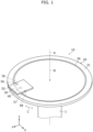
- FIG. 1 is a perspective view illustrating encoder 10 according to an embodiment.
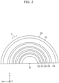
- FIG. 2 is a schematic diagram of rotary plate 20 of encoder 10 in FIG. 1 as viewed in the axis direction.
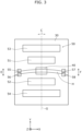
- FIG. 3 is a schematic diagram of emitter 40 and light receiver 50 of encoder 10 in FIG. 1 as viewed in the axis direction.
- FIG. 4 is an explanatory diagram for describing a relationship between the dimensions of first light-receiving region 55 and second light-receiving region 56 and the dimensions of light that irradiates first light-receiving region 55 and second light-receiving region 56 in encoder 10 in FIG. 1 .
- Encoder 10 will be described with reference to FIG. 1 through FIG. 4 .
- FIG. 1 omits illustration of first absolute pattern 22, second absolute pattern 23, first incremental pattern 24, second incremental pattern 25, etc., to avoid complication of the drawing.
- FIG. 2 illustrates only the half of rotary plate 20 to avoid complication of the drawing.
- emitter 40 and first and second light-receiving regions 55 and 56 are shifted in a first direction to avoid complication of the drawing.
- the axis direction indicates the direction in which rotation axis A extends (the Z-axis direction in FIG. 1 , for example).
- encoder 10 detects rotation of detection target 1. Specifically, encoder 10 detects, for example, the position (rotation position) of detection target 1, the rotation direction of detection target 1, the rotation amount of detection target 1, and/or the rotational speed of detection target 1. Detection target 1 rotates about rotation axis A. In the present embodiment, detection target 1 is the rotation shaft (the shaft) of a motor.
- Encoder 10 includes rotary plate 20, substrate 30, emitter 40, and light receiver 50.
- Rotary plate 20 rotates with detection target 1 about rotation axis A.
- Rotary plate 20 includes main body 21, first absolute pattern 22, second absolute pattern 23, first incremental pattern 24, second incremental pattern 25, and annular region 26.
- First absolute pattern 22, second absolute pattern 23, first incremental pattern 24, and second incremental pattern 25 are examples of one or more patterns for detecting the rotation angle of rotary plate 20 (detection target 1).
- Main body 21 is in the shape of a plate whose thickness direction is in the axis direction, and is circular as viewed in the axis direction. Main body 21 is attached to one end portion of detection target 1 in the axis direction and rotates with detection target 1 about rotation axis A. The axis of main body 21 coincides with axis B of annular region 26.
- First absolute pattern 22 is a pattern for detecting an absolute position of detection target 1.
- First absolute pattern 22 is provided on a main surface of main body 21 closer to emitter 40 and is annularly provided surrounding rotation axis A.
- the axis of first absolute pattern 22 coincides with axis B of annular region 26.
- first absolute pattern 22 includes a reflective portion and a non-reflective portion that are arranged annularly.
- the reflective portion is a portion that reflects toward light receiver 50 light emitted from emitter 40
- the non-reflective portion is a portion that does not reflect toward light receiver 50 the light emitted from emitter 40.
- Second absolute pattern 23 is a pattern for detecting an absolute position of detection target 1.
- Second absolute pattern 23 is provided on the main surface of main body 21 closer to emitter 40 and is annularly provided surrounding rotation axis A. The axis of second absolute pattern 23 coincides with axis B of annular region 26.
- Second absolute pattern 23 is provided inwardly of first absolute pattern 22 in the radial direction around axis B of annular region 26.
- second absolute pattern 23 includes a reflective portion and a non-reflective portion that are arranged annularly.
- the reflective portion is a portion that reflects toward light receiver 50 light emitted from emitter 40
- the non-reflective portion is a portion that does not reflect toward light receiver 50 the light emitted from emitter 40.
- First incremental pattern 24 is a pattern for detecting a relative position of detection target 1.
- First incremental pattern 24 is provided on the main surface of main body 21 closer to emitter 40 and is annularly provided surrounding rotation axis A. The axis of first incremental pattern 24 coincides with axis B of annular region 26.
- First incremental pattern 24 is provided outwardly of first absolute pattern 22 in the radial direction around axis B of annular region 26.
- first incremental pattern 24 includes a reflective portion and a non-reflective portion that are arranged annularly.
- the reflective portion is a portion that reflects toward light receiver 50 light emitted from emitter 40
- the non-reflective portion is a portion that does not reflect toward light receiver 50 the light emitted from emitter 40.
- Second incremental pattern 25 is a pattern for detecting a relative position of detection target 1.
- Second incremental pattern 25 is provided on the main surface of main body 21 closer to emitter 40 and is annularly provided surrounding rotation axis A. The axis of second incremental pattern 25 coincides with axis B of annular region 26.
- Second incremental pattern 25 is provided inwardly of second absolute pattern 23 in the radial direction around axis B of annular region 26.
- second incremental pattern 25 includes a reflective portion and a non-reflective portion that are arranged annularly.
- the reflective portion is a portion that reflects toward light receiver 50 light emitted from emitter 40
- the non-reflective portion is a portion that does not reflect toward light receiver 50 the light emitted from emitter 40.
- each of one or more patterns for detecting a rotation angle of rotary plate 20 may transmit the light emitted from emitter 40.
- Annular region 26 is a ring-shaped region that is provided surrounding rotation axis A and reflects light emitted from emitter 40. Annular region 26 reflects toward light receiver 50 the light emitted from emitter 40. Annular region 26 is provided on the main surface of main body 21 closer to emitter 40. The direction in which axis B of annular region 26 extends coincides with the axis direction. FIG. 1 illustrates the state in which axis B of annular region 26 coincides with rotation axis A.
- annular region 26 includes a reflective portion that is annularly disposed in a continuous manner and reflects toward light receiver 50 the light emitted from emitter 40.
- substrate 30 is provided facing rotary plate 20 in the axis direction.
- Substrate 30 is in the shape of a plate whose thickness direction is in the axis direction.
- emitter 40 emits light. Specifically, emitter 40 emits light toward rotary plate 20. More specifically, emitter 40 emits light toward first absolute pattern 22, second absolute pattern 23, first incremental pattern 24, second incremental pattern 25, and annular region 26. Emitter 40 is provided on a main surface of substrate 30 closer to rotary plate 20.
- Light receiver 50 receives light emitted from emitter 40 and arriving via annular region 26, for example.
- Light receiver 50 includes first absolute light-receiving region 51, second absolute light-receiving region 52, first incremental light-receiving region 53, second incremental light-receiving region 54, a first set, and a second set.
- First absolute light-receiving region 51, second absolute light-receiving region 52, first incremental light-receiving region 53, and second incremental light-receiving region 54 are examples of one or more light-receiving regions that receive light emitted from emitter 40 and arriving via one or more patterns.
- First absolute light-receiving region 51 receives light emitted from emitter 40 and arriving via first absolute pattern 22.
- Second absolute light-receiving region 52 receives light emitted from emitter 40 and arriving via second absolute pattern 23.
- First incremental light-receiving region 53 receives light emitted from emitter 40 and arriving via first incremental pattern 24.
- Second incremental light-receiving region 54 receives light emitted from emitter 40 and arriving via second incremental pattern 25.
- the first set includes first light-receiving region 55 and second light-receiving region 56 that are arranged side by side in first direction E intersecting rotation direction C of rotary plate 20.
- the second set includes third light-receiving region 57 and fourth light-receiving region 58 that are arranged side by side in second direction F intersecting rotation direction C, and is provided side by side with the first set in rotation direction C. That is to say, third light-receiving region 57 and fourth light-receiving region 58 are provided side by side with first light-receiving region 55 and second light-receiving region 56 in rotation direction C.
- emitter 40 is interposed between the first set and the second set in rotation direction C. That is to say, emitter 40 is interposed between first and second light-receiving regions 55 and 56 and third and fourth light-receiving regions 57 and 58 in rotation direction C.
- first direction E and second direction F is a direction parallel to the plane orthogonal to rotation axis A.
- each of first direction E and second direction F is a direction (Y-axis direction) parallel to straight line G that is orthogonal to rotation axis A, and the first set and the second set are provided line-symmetrically with respect to straight line G.
- first light-receiving region 55 and second light-receiving region 56 are arranged side by side in the direction parallel to straight line G
- third light-receiving region 57 and fourth light-receiving region 58 are arranged side by side in the direction parallel to straight line G
- first and second light-receiving regions 55 and 56 and third and fourth light-receiving regions 57 and 58 are provided line-symmetrically with respect to straight line G.
- first light-receiving region 55 and third light-receiving region 57 are provided at the same position, and second light-receiving region 56 and fourth light-receiving region 58 are provided at the same position.
- First light-receiving region 55 and second light-receiving region 56 are provided at respective positions where first light-receiving region 55 and second light-receiving region 56 can receive light (see H in FIG. 3 ) emitted from emitter 40 and arriving via annular region 26.
- Third light-receiving region 57 and fourth light-receiving region 58 are provided at respective positions where third light-receiving region 57 and fourth light-receiving region 58 can receive light (see H in FIG. 3 ) emitted from emitter 40 and arriving via annular region 26.
- each of first light-receiving region 55, second light-receiving region 56, third light-receiving region 57, and fourth light-receiving region 58 is a light-receiving region in a light-receiving element. That is to say, for example, light receiver 50 includes a plurality of light-receiving elements.
- Dimension L between the end portion of first light-receiving region 55 farther from second light-receiving region 56 and the end portion of second light-receiving region 56 farther from first light-receiving region 55 in first direction E is greater than dimension W2, in first direction E, of light that is emitted from emitter 40 and, after being incident on annular region 26, irradiates first light-receiving region 55 and second light-receiving region 56.
- the dimension between an end portion of third light-receiving region 57 farther from fourth light-receiving region 58 and an end portion of fourth light-receiving region 58 farther from third light-receiving region 57 in second direction F is greater than the dimension, in second direction F, of light that is emitted from emitter 40 and, after being incident on annular region 26, irradiates third light-receiving region 57 and fourth light-receiving region 58.
- Encoder 10 has been described above.
- FIG. 5 is a block diagram illustrating a functional configuration of encoder 10 in FIG. 1 .
- the functional configuration of encoder 10 will be described with reference to FIG. 5 .
- encoder 10 further includes outputter 60 and calculator 70.
- Outputter 60 outputs a signal corresponding to light received by light receiver 50.
- outputter 60 outputs a signal corresponding to light received by first absolute light-receiving region 51, a signal corresponding to light received by second absolute light-receiving region 52, a signal corresponding to light received by first incremental light-receiving region 53, a signal corresponding to light received by second incremental light-receiving region 54, a signal corresponding to light received by first light-receiving region 55, a signal corresponding to light received by second light-receiving region 56, a signal corresponding to light received by third light-receiving region 57, and a signal corresponding to light received by fourth light-receiving region 58.
- outputter 60 outputs a signal corresponding to the intensity of light received by light receiver 50.
- Outputter 60 outputs a signal indicating a value of X expressed as below and a signal indicating a value of Y expressed as below, where: A1 denotes a signal value corresponding to light received by first light-receiving region 55; A2 denotes a signal value corresponding to light received by second light-receiving region 56; B1 denotes a signal value corresponding to light received by third light-receiving region 57; and B2 denotes a signal value corresponding to light received by fourth light-receiving region 58.
- Outputter 60 also outputs a signal indicating a value of Q expressed as below.
- Q A1 + B1 + A2 + B2
- Outputter 60 also outputs a signal indicating a value of X1 expressed as below and a signal indicating a value of Y1 expressed as below.
- X1 X/Q
- Y1 Y/Q
- Calculator 70 calculates a value of P1 expressed as below, where: P denotes a rotation angle (angle address) of rotary plate 20 detected based on light emitted from emitter 40 and, after being incident on one or more patterns, received by one or more light-receiving regions; ⁇ r denotes an eccentric amount of axis B of annular region 26 relative to rotation axis A (see FIG. 6 ); ⁇ denotes an eccentric phase of axis B of annular region 26 relative to rotation axis A (see FIG. 6 ); and r denotes the radius of annular region 26 (see FIG. 6 ).
- the one or more patterns are first absolute pattern 22, second absolute pattern 23, first incremental pattern 24, and second incremental pattern 25, and the one or more light-receiving regions are first absolute light-receiving region 51, second absolute light-receiving region 52, first incremental light-receiving region 53, and second incremental light-receiving region 54.
- Outputter 60 outputs a signal indicating the value of P1 calculated by calculator 70.
- FIG. 6 is a schematic diagram illustrating a state in which axis B of annular region 26 is eccentric relative to rotation axis A.
- FIG. 7 is a schematic diagram illustrating an example of changes in position of light (see H in FIG. 7 ) that irradiates first light-receiving region 55, second light-receiving region 56, third light-receiving region 57, and fourth light-receiving region 58, caused by rotation of rotary plate 20 in the state in which axis B of annular region 26 is eccentric relative to rotation axis A.
- FIG. 8 is a graph illustrating an example of signals output by outputter 60 when rotary plate 20 rotates in the state in which axis B of annular region 26 is eccentric relative to rotation axis A. The signals output by outputter 60 will be described with reference to FIG. 6 through FIG. 8 .
- rotation of rotary plate 20 causes a change in the position of light that irradiates first light-receiving region 55, second light-receiving region 56, third light-receiving region 57, and fourth light-receiving region 58 after being incident on annular region 26.
- outputter 60 when rotary plate 20 rotates in the state in which axis B of annular region 26 is eccentric relative to rotation axis A, outputter 60 outputs a signal indicating a shift in the X-axis direction and a signal indicating a shift in the Y-axis direction.
- These signals show that axis B of annular region 26 is eccentric relative to rotation axis A.
- the signal indicating a shift in the X-axis direction may be described as a first signal
- the signal indicating a shift in the Y-axis direction may be described as a second signal.
- FIG. 9 is a flow chart illustrating an example of the calculation method performed by calculator 70 of encoder 10 in FIG. 1 . An example of the calculation method performed by calculator 70 will be described with reference to FIG. 9 .
- first, calculator 70 matches the amplitude of the first signal and the amplitude of the second signal (step S1).
- the first signal is a signal indicating a shift in the X-axis direction
- the second signal is a signal indicating a shift in the Y-axis direction.
- calculator 70 determines the eccentric phase of axis B relative to rotation axis A and the eccentric amount of axis B relative to rotation axis A (step S2). For example, the eccentric phase of axis B relative to rotation axis A is calculated using the value of X indicated by the first signal and the value of Y indicated by the second signal. Also, for example, the eccentric amount of axis B relative to rotation axis A is calculated from the amplitude of the first signal. Furthermore, for example, the eccentric amount of axis B relative to rotation axis A is calculated from a function or a table prepared in advance.
- the amplitude used for calculating the eccentric amount may be sequentially determined from a square root of sum of squares of the first signal and the second signal whose amplitudes have been matched.
- the amplitude which is denoted by G and is used for calculating the eccentric amount, may be calculated in real time by the equation below.
- G X 2 + Y 2
- Calculator 70 calculates an angle after determining the eccentric phase and the eccentric amount (step S3).
- a true detection address which is denoted by P1
- P1 P ⁇ tan -1 ( ⁇ r ⁇ sin ⁇ /r).
- P denotes a rotation angle of rotary plate 20 detected based on light emitted from emitter 40 and, after being incident on one or more patterns, received by light receiver 50
- r denotes the radius of annular region 26
- ⁇ r denotes an eccentric amount of axis B of annular region 26 relative to rotation axis A
- ⁇ denotes an eccentric phase of axis B of annular region 26 relative to rotation axis A.
- FIG. 10 is a flow chart illustrating another example of the calculation method performed by calculator 70 of encoder 10 in FIG. 1 . Another example of the calculation method performed by calculator 70 will be described with reference to FIG. 10 . Note that the following description mainly focuses on the differences from the example of the calculation method illustrated in FIG. 9 .
- calculator 70 obtains the amplitude of the second signal (step S11). For example, calculator 70 obtains the amplitude of the second signal prior to one rotation. For example, calculator 70 obtains the amplitude of the second signal from one rotation in a test mode or one rotation in continuous rotations. Specifically, for example, calculator 70 obtains the amplitude of the second signal from arbitrary 360-degree data. Also, for example, calculator 70 obtains the amplitude of the second signal by clipping a peak value from arbitrary 180-degree data.
- calculator 70 determines the eccentric phase of axis B relative to rotation axis A and the eccentric amount of axis B relative to rotation axis A (step S2). For example, calculator 70 estimates the waveform of the second signal from the amplitude of the second signal obtained, and determines the eccentric phase of axis B relative to rotation axis A from: the value of Y indicated by the second signal output from outputter 60; and the increase and decrease tendency of the signal level of the second signal.
- calculator 70 may calculate the eccentric phase etc., of axis B relative to rotation axis A without using the first signal.
- encoder 10 can more precisely detect the eccentricity of rotary plate 20 relative to detection target 1.
- encoder 10 since encoder 10 includes first light-receiving region 55, second light-receiving region 56, third light-receiving region 57, and fourth light-receiving region 58 on single substrate 30, encoder 10 can be downsized and less expensive.
- Encoder 10 according to Embodiment 1 has been described above.
- Encoder 10 includes: emitter 40 that emits light; rotary plate 20 that rotates and includes annular region 26 that reflects the light emitted from emitter 40, annular region 26 being provided surrounding rotation axis A of rotary plate 20; and light receiver 50 that receives light emitted from emitter 40 and arriving via annular region 26.
- Light receiver 50 includes: a first set that includes first light-receiving region 55 and second light-receiving region 56 that are arranged side by side in first direction E intersecting rotation direction C of rotary plate 20; and a second set that includes third light-receiving region 57 and fourth light-receiving region 58 that are arranged side by side in second direction F intersecting rotation direction C and that is provided side by side with the first set in rotation direction C.
- light receiver 50 includes: the first set that includes first light-receiving region 55 and second light-receiving region 56 that are arranged side by side in first direction E intersecting rotation direction C of rotary plate 20; and the second set that includes third light-receiving region 57 and fourth light-receiving region 58 that are arranged side by side in second direction F intersecting rotation direction C and that is provided side by side with the first set in rotation direction C.
- rotation of rotary plate 20 causes a change in the position of light received by first light-receiving region 55, second light-receiving region 56, third light-receiving region 57, and fourth light-receiving region 58, thus enabling precise detection of the eccentricity of rotary plate 20 relative to detection target 1.
- encoder 10 further includes outputter 60 that outputs a signal indicating a value of X expressed as below and a signal indicating a value of Y expressed as below:
- X A1 + B2 ⁇ B1 + A2
- Y A1 + B1 ⁇ A2 + B2
- A1 denotes a signal value corresponding to light received by first light-receiving region 55
- A2 denotes a signal value corresponding to light received by second light-receiving region 56
- B1 denotes a signal value corresponding to light received by third light-receiving region 57
- B2 denotes a signal value corresponding to light received by fourth light-receiving region 58.
- rotary plate 20 includes one or more patterns for detecting a rotation angle of rotary plate 20
- light receiver 50 includes one or more light-receiving regions that receive light emitted from emitter 40 and arriving via the one or more patterns.
- Outputter 60 outputs a signal indicating the value of P1 calculated by calculator 70.
- emitter 40 is interposed between the first set and the second set in rotation direction C.
- first light-receiving region 55 second light-receiving region 56, third light-receiving region 57, and fourth light-receiving region 58, thus enabling further precise detection of the eccentricity of rotary plate 20 relative to detection target 1.
- each of first direction E and second direction F is a direction parallel to straight line G orthogonal to rotation axis A, and the first set and the second set are provided line-symmetrically with respect to straight line G.
- first light-receiving region 55 second light-receiving region 56, third light-receiving region 57, and fourth light-receiving region 58 and inhibit variation in the amount of light received by first light-receiving region 55, second light-receiving region 56, third light-receiving region 57, and fourth light-receiving region 58, thus enabling further precise detection of the eccentricity of rotary plate 20 relative to detection target 1.
- rotation of rotary plate 20 can cause an appropriate change in the position of light received by first light-receiving region 55 and second light-receiving region 56 and the position of light received by third light-receiving region 57 and fourth light-receiving region 58, thus enabling further precise detection of the eccentricity of rotary plate 20 relative to detection target 1.
- rotation of rotary plate 20 can cause an appropriate change in the position of light received by first light-receiving region 55 and second light-receiving region 56, thus enabling further precise detection of the eccentricity of rotary plate 20 relative to detection target 1.
- FIG. 11 is a schematic diagram of rotary plate 20a of an encoder according to Embodiment 2 as viewed in the axis direction.
- FIG. 12 is a schematic diagram of emitter 40a and light receiver 50a of the encoder in FIG. 11 as viewed in the axis direction.
- a configuration of the encoder according to Embodiment 2 will be described with reference to FIG. 11 and FIG. 12 . Note that the following description mainly focuses on the differences from encoder 10 according to Embodiment 1.
- FIG. 11 illustrates only the half of rotary plate 20a to avoid complication of the drawing.
- the encoder according to Embodiment 2 includes rotary plate 20a different from rotary plate 20. Also, as illustrated in FIG. 12 , the encoder according to Embodiment 2 includes emitter 40a different from emitter 40 and light receiver 50a different from light receiver 50. The encoder according to Embodiment 2 is different from encoder 10 mainly in these aspects.
- rotary plate 20a includes main body 21, absolute pattern 22a, incremental pattern 24a, and annular region 26a.
- Annular region 26a is a ring-shaped region that is provided surrounding rotation axis A and reflects the light emitted from emitter 40a. Annular region 26a reflects toward light receiver 50a the light emitted from emitter 40a. Annular region 26a is provided on the main surface of main body 21 closer to emitter 40a. The direction in which axis B of annular region 26a extends coincides with the axis direction. For example, annular region 26a includes a reflective portion that is annularly disposed in a continuous manner and reflects toward light receiver 50a the light emitted from emitter 40a.
- emitter 40a emits light. Specifically, emitter 40a emits light toward rotary plate 20a. More specifically, emitter 40a emits light toward absolute pattern 22a, incremental pattern 24a, and annular region 26a. Emitter 40a is provided on the main surface of substrate 30 closer to rotary plate 20a.
- Light receiver 50a receives light emitted from emitter 40a and arriving via annular region 26a, for example.
- Light receiver 50a includes first absolute light-receiving region 51a, second absolute light-receiving region 52a, first incremental light-receiving region 53a, second incremental light-receiving region 54a, a first set, and a second set.
- First absolute light-receiving region 51a and second absolute light-receiving region 52a each receive light emitted from emitter 40a and arriving via absolute pattern 22a.
- First absolute light-receiving region 51a and second absolute light-receiving region 52a are arranged out of alignment with each other in rotation direction C.
- First incremental light-receiving region 53a and second incremental light-receiving region 54a each receive light emitted from emitter 40a and arriving via incremental pattern 24a.
- First incremental light-receiving region 53a and second incremental light-receiving region 54a are arranged out of alignment with each other in rotation direction C.
- the first set includes first light-receiving region 55a and second light-receiving region 56a that are arranged side by side in first direction E intersecting rotation direction C of rotary plate 20a.
- the second set includes third light-receiving region 57a and fourth light-receiving region 58a that are arranged side by side in second direction F intersecting rotation direction C, and is provided side by side with the first set in rotation direction C.
- first light-receiving region 55a closer to second light-receiving region 56a, an end portion of second light-receiving region 56a closer to first light-receiving region 55a, an end portion of third light-receiving region 57a closer to fourth light-receiving region 58a, and an end portion of fourth light-receiving region 58a closer to third light-receiving region 57a are each in the shape of a straight line extending in the tangential direction with respect to rotation direction C.
- an end portion of first light-receiving region 55a farther from second light-receiving region 56a, an end portion of second light-receiving region 56a farther from first light-receiving region 55a, an end portion of third light-receiving region 57a farther from fourth light-receiving region 58a, and an end portion of fourth light-receiving region 58a farther from third light-receiving region 57a are each in the shape of a straight line extending in the tangential direction with respect to rotation direction C.
- the end portion of first light-receiving region 55a closer to second light-receiving region 56a, the end portion of second light-receiving region 56a closer to first light-receiving region 55a, the end portion of third light-receiving region 57a closer to fourth light-receiving region 58a, and the end portion of fourth light-receiving region 58a closer to third light-receiving region 57a are each in the shape of a straight line extending in the tangential direction with respect to rotation direction C.
- first light-receiving region 55a second light-receiving region 56a, third light-receiving region 57a, and fourth light-receiving region 58a, thus enabling further precise detection of the eccentricity of rotary plate 20a relative to detection target 1.
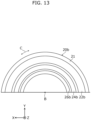
- FIG. 13 is a schematic diagram of rotary plate 20b of an encoder according to Embodiment 3 as viewed in the axis direction.
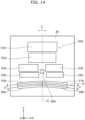
- FIG. 14 is a schematic diagram of emitter 40b and light receiver 50b of the encoder in FIG. 13 as viewed in the axis direction.
- a configuration of the encoder according to Embodiment 3 will be described with reference to FIG. 13 and FIG. 14 . Note that the following description mainly focuses on the differences from encoder 10 according to Embodiment 1.
- FIG. 13 illustrates only the half of rotary plate 20b to avoid complication of the drawing.
- the encoder according to Embodiment 3 includes rotary plate 20b different from rotary plate 20. Also, as illustrated in FIG. 14 , the encoder according to Embodiment 3 includes emitter 40b different from emitter 40 and light receiver 50b different from light receiver 50. The encoder according to Embodiment 3 is different from encoder 10 mainly in these aspects.
- rotary plate 20b includes main body 21, absolute pattern 22b, incremental pattern 24b, and annular region 26b.
- Annular region 26b is a ring-shaped region that is provided surrounding rotation axis A and reflects the light emitted from emitter 40b. Annular region 26b reflects toward light receiver 50b the light emitted from emitter 40b. Annular region 26b is provided on the main surface of main body 21 closer to emitter 40b. The direction in which axis B of annular region 26b extends coincides with the axis direction. For example, annular region 26b includes a reflective portion that is annularly disposed in a continuous manner and reflects toward light receiver 50b the light emitted from emitter 40b.
- Annular region 26b is located inwardly of absolute pattern 22b and incremental pattern 24b in the radial direction around axis center B. That is to say, among absolute pattern 22b, incremental pattern 24b, and annular region 26b, annular region 26b is located most inwardly in the radial direction.
- emitter 40b emits light. Specifically, emitter 40b emits light toward rotary plate 20b. More specifically, emitter 40b emits light toward absolute pattern 22b, incremental pattern 24b, and annular region 26b. Emitter 40b is provided on the main surface of substrate 30 closer to rotary plate 20b.
- Light receiver 50b receives, for example, light emitted from emitter 40b and arriving via annular region 26b.
- Light receiver 50b includes first absolute light-receiving region 51b, second absolute light-receiving region 52b, first incremental light-receiving regions 53b, second incremental light-receiving regions 54b, a first set, and a second set.
- First absolute light-receiving region 51b and second absolute light-receiving region 52b each receive light emitted from emitter 40b and arriving via absolute pattern 22b.
- First incremental light-receiving regions 53b and second incremental light-receiving regions 54b each receive light emitted from emitter 40b and arriving via incremental pattern 24b.
- the first set includes first light-receiving region 55b and second light-receiving region 56b that are arranged side by side in first direction E intersecting rotation direction C of rotary plate 20b.
- the second set includes third light-receiving region 57b and fourth light-receiving region 58b that are arranged side by side in second direction F intersecting rotation direction C, and is provided side by side with the first set in rotation direction C.
- Each of the first set and the second set is located inwardly of emitter 40b in the radial direction around rotation axis A. That is to say, each of first light-receiving region 55b, second light-receiving region 56b, third light-receiving region 57b, and fourth light-receiving region 58b is located inwardly of emitter 40b in the radial direction around rotation axis A.
- first light-receiving region 55b closer to second light-receiving region 56b, an end portion of second light-receiving region 56b closer to first light-receiving region 55b, an end portion of third light-receiving region 57b closer to fourth light-receiving region 58b, and an end portion of fourth light-receiving region 58b closer to third light-receiving region 57b are each in the shape of a curved line extending in rotation direction C.
- an end portion of first light-receiving region 55b farther from second light-receiving region 56b, an end portion of second light-receiving region 56b farther from first light-receiving region 55b, an end portion of third light-receiving region 57b farther from fourth light-receiving region 58b, and an end portion of fourth light-receiving region 58b farther from third light-receiving region 57b are each in the shape of a curved line extending in rotation direction C.
- First light-receiving region 55b, second light-receiving region 56b, third light-receiving region 57b, and fourth light-receiving region 58b are each in the shape of an arc extending in rotation direction C.
- First direction E is a direction that coincides with the radial direction around rotation axis A
- second direction F is a direction that coincides with the radial direction around rotation axis A and intersects first direction E.
- First light-receiving region 55b and third light-receiving region 57b are adjacent to each other in rotation direction C, and second light-receiving region 56b and fourth light-receiving region 58b are adjacent to each other in rotation direction C.
- each of the first set and the second set is located inwardly of emitter 40b in the radial direction around rotation axis A.
- first light-receiving region 55b second light-receiving region 56b, third light-receiving region 57b, and fourth light-receiving region 58b, thus enabling further precise detection of the eccentricity of rotary plate 20b relative to detection target 1.
- an end portion of first light-receiving region 55b closer to second light-receiving region 56b, an end portion of second light-receiving region 56b closer to first light-receiving region 55b, an end portion of third light-receiving region 57b closer to fourth light-receiving region 58b, and an end portion of fourth light-receiving region 58b closer to third light-receiving region 57b are each in the shape of a curved line extending in rotation direction C.
- first light-receiving region 55b second light-receiving region 56b, third light-receiving region 57b, and fourth light-receiving region 58b, thus enabling further precise detection of the eccentricity of rotary plate 20b relative to detection target 1.
- first direction E is a direction that coincides with the radial direction around rotation axis A
- second direction F is a direction that coincides with the radial direction around rotation axis A and intersects first direction E.
- first light-receiving region 55b second light-receiving region 56b, third light-receiving region 57b, and fourth light-receiving region 58b, thus enabling further precise detection of the eccentricity of rotary plate 20b relative to detection target 1.
- FIG. 15 is a schematic diagram of emitter 40c and light receiver 50c of an encoder according to Embodiment 4 as viewed in the axis direction. A configuration of the encoder according to Embodiment 4 will be described with reference to FIG. 15 . Note that the following description mainly focuses on the differences from encoder 10 according to Embodiment 1.
- the encoder according to Embodiment 4 is mainly different from encoder 10 in including a rotary plate (not illustrated) different from rotary plate 20, emitter 40c different from emitter 40, and light receiver 50c different from light receiver 50.
- Emitter 40c emits light. Specifically, emitter 40c emits light toward the rotary plate. More specifically, emitter 40c emits light toward, for example, an annular region (not illustrated) of the rotary plate. Emitter 40c is provided on the main surface of substrate 30 closer to the rotary plate.
- Light receiver 50c receives light emitted from emitter 40c and arriving via the annular region of the rotary plate of the encoder according to Embodiment 4, for example.
- Light receiver 50c includes first absolute light-receiving region 51c, second absolute light-receiving region 52c, first incremental light-receiving region 53c, second incremental light-receiving region 54c, a first set, and a second set.
- First absolute light-receiving region 51c and second absolute light-receiving region 52c each receive light emitted from emitter 40c and arriving via an absolute pattern of the rotary plate.
- First incremental light-receiving region 53c and second incremental light-receiving region 54c each receive light emitted from emitter 40c and arriving via an incremental pattern of the rotary plate.
- the first set includes first light-receiving region 55c and second light-receiving region 56c that are arranged side by side in first direction E intersecting rotation direction C of the rotary plate.
- the second set includes third light-receiving region 57c and fourth light-receiving region 58c that are arranged side by side in second direction F intersecting rotation direction C, and is provided side by side with the first set in rotation direction C.
- a phase difference of 90 degrees is provided between the first set and the second set in rotation direction C. That is to say, the second set is provided at a position shifted from the first set by 90 degrees in rotation direction C.
- FIG. 16 is an explanatory diagram for describing a relationship between the dimensions of first light-receiving region 55d and second light-receiving region 56d and the dimensions of light that irradiates first light-receiving region 55d and second light-receiving region 56d in an encoder according to Embodiment 5.
- a configuration of the encoder according to Embodiment 5 will be described with reference to FIG. 16 .
- L is designed to, for example, inhibit the reflected light from going outside the light-receiving regions (first light-receiving region 55d and second light-receiving region 56d). Note that the same relational expressions are satisfied for a third light-receiving region and a fourth light-receiving region as well.
- rotation of the rotary plate can cause an appropriate change in the position of light received by first light-receiving region 55d and second light-receiving region 56d, thus enabling further precise detection of the eccentricity of the rotary plate relative to detection target 1.
- FIG. 17 is an explanatory diagram for describing a relationship between the dimensions of first light-receiving region 55e and second light-receiving region 56e and the dimensions of light that irradiates first light-receiving region 55e and second light-receiving region 56e in an encoder according to Embodiment 6.
- a configuration of the encoder according to Embodiment 6 will be described with reference to FIG. 17 . Note that the following description mainly focuses on the differences from encoder 10 according to Embodiment 1.
- the encoder according to Embodiment 6 includes emitter 40e, annular region 26e, first light-receiving region 55e, and second light-receiving region 56e.
- Annular region 26e is recessed in the axis direction in which rotation axis A extends. Light emitted from emitter 40e and reflected by annular region 26e irradiates first light-receiving region 55e and second light-receiving region 56e while converging. Similarly, light emitted from emitter 40e and reflected by annular region 26e also irradiates a third light-receiving region and a fourth light-receiving region while converging.
- annular region 26e is recessed in the axis direction in which rotation axis A extends.
- FIG. 18 is a flow chart illustrating an example of an attachment method according to Embodiment 7. An example of the attachment method according to Embodiment 7 will be described with reference to FIG. 18 . Described here is an attachment method for attaching encoder 10 to detection target 1.
- rotary plate 20 is attached to detection target 1 (step S21).
- rotary plate 20 is attached to detection target 1 by using a screw, for example.
- rotary plate 20 When rotary plate 20 is attached to detection target 1, rotary plate 20 is rotated about rotation axis A (step S22). Note that rotary plate 20 need not necessarily be rotated.
- a signal output by outputter 60 is obtained (step S23).
- a value of X and a value of Y are obtained from the signal output by outputter 60.
- step S24 When each of the value of X and the value of Y is not 0 (No in step S24), the attachment position of rotary plate 20 attached to detection target 1 is adjusted (step S25).
- the attachment method according to Embodiment 7 is an attachment method of attaching encoder 10 to detection target 1.
- Encoder 10 includes: emitter 40 that emits light; rotary plate 20 that rotates and includes annular region 26 that reflects the light emitted from emitter 40, annular region 26 being provided surrounding rotation axis A of rotary plate 20; and light receiver 50 that receives light emitted from emitter 40 and arriving via annular region 26.
- Light receiver 50 includes: a first set that includes first light-receiving region 55 and second light-receiving region 56 that are arranged side by side in first direction E intersecting rotation direction C of rotary plate 20; and a second set that includes third light-receiving region 57 and fourth light-receiving region 58 that are arranged side by side in second direction F intersecting rotation direction C and that is provided side by side with the first set in rotation direction C.
- Encoder 10 further includes outputter 60 that outputs a signal indicating a value of X expressed as below and a signal indicating a value of Y expressed as below:
- X A1 + B2 ⁇ B1 + A2
- Y A1 + B1 ⁇ A2 + B2
- A1 denotes a signal value corresponding to light received by first light-receiving region 55
- A2 denotes a signal value corresponding to light received by second light-receiving region 56
- B1 denotes a signal value corresponding to light received by third light-receiving region 57
- B2 denotes a signal value corresponding to light received by fourth light-receiving region 58.
- the attachment method includes: step S21 of attaching rotary plate 20 to detection target 1; and after attaching rotary plate 20 to detection target 1, step S23 of causing outputter 60 to output the signal indicating the value of X and the signal indicating the value of Y.
- step S21 of attaching rotary plate 20 to detection target 1 step S21 of attaching rotary plate 20 to detection target 1; and after attaching rotary plate 20 to detection target 1, step S23 of causing outputter 60 to output the signal indicating the value of X and the signal indicating the value of Y.
- annular regions 26 through 26e reflect light; however, the present disclosure is not limited to this.
- the annular region may transmit the light emitted from the emitter, toward the light receiver.
- each constituent element may be configured as dedicated hardware or may be realized by executing a software program suitable for the constituent element.
- Each of the constituent elements may be realized by means of a program executor, such as a central processing unit (CPU) or a processor, reading and executing a software program recorded on a recording medium such as a hard disk or semiconductor memory.
- the software programs for realizing, for example, the calculation methods and the attachment method according to the above embodiments are computer programs that cause a computer to perform the steps of the flow charts in FIG. 9 , FIG. 10 , and FIG. 18 .
- the present disclosure may also be a computer-readable recording medium, such as a flexible disk, a hard disk, a compact disc (CD)-ROM, a DVD, a DVD-ROM, a DVD-RAM, a Blu-ray Disc (BD; registered trademark), semiconductor memory, etc., having recording thereon the computer program or the digital signal.
- a computer-readable recording medium such as a flexible disk, a hard disk, a compact disc (CD)-ROM, a DVD, a DVD-ROM, a DVD-RAM, a Blu-ray Disc (BD; registered trademark), semiconductor memory, etc.
- the present disclosure may transmit the computer program or the digital signal via, for example, a telecommunication line, a wireless or wired communication line, a network such as the Internet, or data broadcasting.
- the program or the digital signal may be implemented by another independent computer system by recording the program or the digital signal on a recording medium and transporting it or by transporting the program or the digital signal via a network, etc.
- the encoders according to the present disclosure can be used in detecting rotation of, for example, the rotary shaft of a motor that rotates and drives a load.
Landscapes
- Physics & Mathematics (AREA)
- General Physics & Mathematics (AREA)
- Engineering & Computer Science (AREA)
- Signal Processing (AREA)
- Optical Transform (AREA)
Applications Claiming Priority (2)
| Application Number | Priority Date | Filing Date | Title |
|---|---|---|---|
| JP2021212447 | 2021-12-27 | ||
| PCT/JP2022/045603 WO2023127468A1 (ja) | 2021-12-27 | 2022-12-12 | エンコーダ、および取付方法 |
Publications (3)
| Publication Number | Publication Date |
|---|---|
| EP4459236A1 true EP4459236A1 (de) | 2024-11-06 |
| EP4459236A4 EP4459236A4 (de) | 2025-04-16 |
| EP4459236B1 EP4459236B1 (de) | 2026-04-08 |
Family
ID=86998670
Family Applications (1)
| Application Number | Title | Priority Date | Filing Date |
|---|---|---|---|
| EP22915692.2A Active EP4459236B1 (de) | 2021-12-27 | 2022-12-12 | Codierer und befestigungsverfahren |
Country Status (5)
| Country | Link |
|---|---|
| US (1) | US20250060230A1 (de) |
| EP (1) | EP4459236B1 (de) |
| JP (1) | JP7829147B2 (de) |
| CN (1) | CN118369553A (de) |
| WO (1) | WO2023127468A1 (de) |
Family Cites Families (13)
| Publication number | Priority date | Publication date | Assignee | Title |
|---|---|---|---|---|
| US4990909A (en) * | 1988-09-30 | 1991-02-05 | Yokogawa Electric Corporation | Revolution counter using a magnetic bubble device for multi-turn absolute encoder |
| US5073710A (en) * | 1989-09-21 | 1991-12-17 | Copal Company Limited | Optical displacement detector including a displacement member's surface having a diffractive pattern and a holographic lens pattern |
| JPH07140844A (ja) | 1993-06-22 | 1995-06-02 | Fuji Xerox Co Ltd | 画像形成装置の回転部材の角速度検出装置 |
| JP4956217B2 (ja) * | 2007-02-15 | 2012-06-20 | キヤノン株式会社 | 回転角度検出装置 |
| JP2010145333A (ja) * | 2008-12-22 | 2010-07-01 | Nikon Corp | ロータリエンコーダ |
| JP5146366B2 (ja) | 2009-03-09 | 2013-02-20 | 株式会社安川電機 | 光学式エンコーダ |
| JP5434760B2 (ja) * | 2010-04-08 | 2014-03-05 | 株式会社ニコン | エンコーダ |
| JP5692584B2 (ja) * | 2011-02-15 | 2015-04-01 | 株式会社安川電機 | サーボモータ製造方法、サーボモータ製造装置、サーボモータ、エンコーダ |
| JP2014013163A (ja) * | 2012-07-04 | 2014-01-23 | Yaskawa Electric Corp | エンコーダ及びモータ |
| JP6263965B2 (ja) * | 2013-11-05 | 2018-01-24 | 株式会社安川電機 | エンコーダ、エンコーダ付きモータ、サーボシステム |
| CN107850466B (zh) * | 2015-07-17 | 2021-01-08 | 株式会社尼康 | 编码器装置、驱动装置、旋转信息取得方法以及记录介质 |
| DE102019210274A1 (de) * | 2019-07-11 | 2021-01-14 | Dr. Johannes Heidenhain Gmbh | Optische Positionsmesseinrichtung |
| JP6924419B2 (ja) * | 2019-09-06 | 2021-08-25 | 株式会社安川電機 | エンコーダ、サーボモータ、サーボシステム |
-
2022
- 2022-12-12 CN CN202280081293.3A patent/CN118369553A/zh active Pending
- 2022-12-12 JP JP2023570803A patent/JP7829147B2/ja active Active
- 2022-12-12 WO PCT/JP2022/045603 patent/WO2023127468A1/ja not_active Ceased
- 2022-12-12 EP EP22915692.2A patent/EP4459236B1/de active Active
- 2022-12-12 US US18/718,344 patent/US20250060230A1/en active Pending
Also Published As
| Publication number | Publication date |
|---|---|
| JP7829147B2 (ja) | 2026-03-13 |
| WO2023127468A1 (ja) | 2023-07-06 |
| US20250060230A1 (en) | 2025-02-20 |
| EP4459236B1 (de) | 2026-04-08 |
| EP4459236A4 (de) | 2025-04-16 |
| CN118369553A (zh) | 2024-07-19 |
| JPWO2023127468A1 (de) | 2023-07-06 |
Similar Documents
| Publication | Publication Date | Title |
|---|---|---|
| EP3301401B1 (de) | Exzentrizitätsberechnungsverfahren, drehgeber, robotischer arm und robotervorrichtung | |
| CN101529211B (zh) | 采用具有公共刻线基板的多个子编码器的旋转光学编码器 | |
| EP2343510A2 (de) | Drehcodierer | |
| CN104048686A (zh) | 位置检测装置、透镜装置、摄像系统和机床装置 | |
| US11579001B2 (en) | Calibrator, encoder, driving device, stage device, robot, encoder manufacturing method, and calibration program | |
| JP5168106B2 (ja) | 回転円板の偏心測定方法 | |
| CN112212809A (zh) | 光学位置测量装置 | |
| JP2021018126A (ja) | エンコーダ、サーボモータ、サーボシステム | |
| JP5939956B2 (ja) | 変位検出装置 | |
| EP4459236B1 (de) | Codierer und befestigungsverfahren | |
| JP2017187490A (ja) | 角度を測定するための装置及び方法 | |
| JP2012083236A (ja) | 角度検出装置 | |
| JP2003057074A (ja) | ロータリーエンコーダ装置 | |
| JP6940105B1 (ja) | エンコーダ装置 | |
| JP4900140B2 (ja) | 光学式エンコーダ | |
| JP7843453B2 (ja) | エンコーダ、および制御システム | |
| WO2023243303A1 (ja) | ロータリエンコーダ | |
| JP6106839B2 (ja) | エンコーダ | |
| WO2022059750A1 (ja) | エンコーダ装置、その使用方法、その位置決め方法、及び位置検出方法 | |
| JP4633607B2 (ja) | 回転駆動装置 | |
| JPH063164A (ja) | 回転位置検出装置 | |
| JP7664719B2 (ja) | 位置測定装置 | |
| JP2009121901A (ja) | トルク計測装置 | |
| WO2026058523A1 (ja) | 変位測定装置、及び変位測定方法 | |
| CN118922688A (zh) | 编码器 |
Legal Events
| Date | Code | Title | Description |
|---|---|---|---|
| STAA | Information on the status of an ep patent application or granted ep patent |
Free format text: STATUS: THE INTERNATIONAL PUBLICATION HAS BEEN MADE |
|
| PUAI | Public reference made under article 153(3) epc to a published international application that has entered the european phase |
Free format text: ORIGINAL CODE: 0009012 |
|
| STAA | Information on the status of an ep patent application or granted ep patent |
Free format text: STATUS: REQUEST FOR EXAMINATION WAS MADE |
|
| 17P | Request for examination filed |
Effective date: 20240531 |
|
| AK | Designated contracting states |
Kind code of ref document: A1 Designated state(s): AL AT BE BG CH CY CZ DE DK EE ES FI FR GB GR HR HU IE IS IT LI LT LU LV MC ME MK MT NL NO PL PT RO RS SE SI SK SM TR |
|
| DAV | Request for validation of the european patent (deleted) | ||
| DAX | Request for extension of the european patent (deleted) | ||
| A4 | Supplementary search report drawn up and despatched |
Effective date: 20250313 |
|
| RIC1 | Information provided on ipc code assigned before grant |
Ipc: G01D 5/347 20060101AFI20250307BHEP |
|
| GRAP | Despatch of communication of intention to grant a patent |
Free format text: ORIGINAL CODE: EPIDOSNIGR1 |
|
| STAA | Information on the status of an ep patent application or granted ep patent |
Free format text: STATUS: GRANT OF PATENT IS INTENDED |
|
| INTG | Intention to grant announced |
Effective date: 20251128 |
|
| GRAS | Grant fee paid |
Free format text: ORIGINAL CODE: EPIDOSNIGR3 |
|
| GRAA | (expected) grant |
Free format text: ORIGINAL CODE: 0009210 |
|
| STAA | Information on the status of an ep patent application or granted ep patent |
Free format text: STATUS: THE PATENT HAS BEEN GRANTED |
|
| AK | Designated contracting states |
Kind code of ref document: B1 Designated state(s): AL AT BE BG CH CY CZ DE DK EE ES FI FR GB GR HR HU IE IS IT LI LT LU LV MC ME MK MT NL NO PL PT RO RS SE SI SK SM TR |
|
| REG | Reference to a national code |
Ref country code: CH Ref legal event code: F10 Free format text: ST27 STATUS EVENT CODE: U-0-0-F10-F00 (AS PROVIDED BY THE NATIONAL OFFICE) Effective date: 20260408 Ref country code: GB Ref legal event code: FG4D |
|
| REG | Reference to a national code |
Ref country code: DE Ref legal event code: R096 Ref document number: 602022034358 Country of ref document: DE |