EP4462006A1 - Behälterverbindungssystem und flüssigkeitsbehälter - Google Patents
Behälterverbindungssystem und flüssigkeitsbehälter Download PDFInfo
- Publication number
- EP4462006A1 EP4462006A1 EP22918822.2A EP22918822A EP4462006A1 EP 4462006 A1 EP4462006 A1 EP 4462006A1 EP 22918822 A EP22918822 A EP 22918822A EP 4462006 A1 EP4462006 A1 EP 4462006A1
- Authority
- EP
- European Patent Office
- Prior art keywords
- container
- conduit
- fluid
- fluid container
- connecting valve
- Prior art date
- Legal status (The legal status is an assumption and is not a legal conclusion. Google has not performed a legal analysis and makes no representation as to the accuracy of the status listed.)
- Pending
Links
Images




Classifications
-
- B—PERFORMING OPERATIONS; TRANSPORTING
- B01—PHYSICAL OR CHEMICAL PROCESSES OR APPARATUS IN GENERAL
- B01D—SEPARATION
- B01D29/00—Filters with filtering elements stationary during filtration, e.g. pressure or suction filters, not covered by groups B01D24/00 - B01D27/00; Filtering elements therefor
- B01D29/11—Filters with filtering elements stationary during filtration, e.g. pressure or suction filters, not covered by groups B01D24/00 - B01D27/00; Filtering elements therefor with bag, cage, hose, tube, sleeve or like filtering elements
- B01D29/13—Supported filter elements
- B01D29/23—Supported filter elements arranged for outward flow filtration
-
- F—MECHANICAL ENGINEERING; LIGHTING; HEATING; WEAPONS; BLASTING
- F16—ENGINEERING ELEMENTS AND UNITS; GENERAL MEASURES FOR PRODUCING AND MAINTAINING EFFECTIVE FUNCTIONING OF MACHINES OR INSTALLATIONS; THERMAL INSULATION IN GENERAL
- F16L—PIPES; JOINTS OR FITTINGS FOR PIPES; SUPPORTS FOR PIPES, CABLES OR PROTECTIVE TUBING; MEANS FOR THERMAL INSULATION IN GENERAL
- F16L37/00—Couplings of the quick-acting type
- F16L37/28—Couplings of the quick-acting type with fluid cut-off means
- F16L37/38—Couplings of the quick-acting type with fluid cut-off means with fluid cut-off means in only one of two pipe-end fittings
- F16L37/40—Couplings of the quick-acting type with fluid cut-off means with fluid cut-off means in only one of two pipe-end fittings with a lift valve being opened automatically when the coupling is applied
-
- B—PERFORMING OPERATIONS; TRANSPORTING
- B01—PHYSICAL OR CHEMICAL PROCESSES OR APPARATUS IN GENERAL
- B01D—SEPARATION
- B01D35/00—Filtering devices having features not specifically covered by groups B01D24/00 - B01D33/00, or for applications not specifically covered by groups B01D24/00 - B01D33/00; Auxiliary devices for filtration; Filter housing constructions
- B01D35/14—Safety devices specially adapted for filtration; Devices for indicating clogging
-
- B—PERFORMING OPERATIONS; TRANSPORTING
- B01—PHYSICAL OR CHEMICAL PROCESSES OR APPARATUS IN GENERAL
- B01D—SEPARATION
- B01D35/00—Filtering devices having features not specifically covered by groups B01D24/00 - B01D33/00, or for applications not specifically covered by groups B01D24/00 - B01D33/00; Auxiliary devices for filtration; Filter housing constructions
- B01D35/30—Filter housing constructions
- B01D35/306—Filter mounting adapter
-
- B—PERFORMING OPERATIONS; TRANSPORTING
- B01—PHYSICAL OR CHEMICAL PROCESSES OR APPARATUS IN GENERAL
- B01D—SEPARATION
- B01D46/00—Filters or filtering processes specially modified for separating dispersed particles from gases or vapours
- B01D46/0002—Casings; Housings; Frame constructions
- B01D46/0004—Details of removable closures, lids, caps or filter heads
-
- B—PERFORMING OPERATIONS; TRANSPORTING
- B01—PHYSICAL OR CHEMICAL PROCESSES OR APPARATUS IN GENERAL
- B01D—SEPARATION
- B01D46/00—Filters or filtering processes specially modified for separating dispersed particles from gases or vapours
- B01D46/24—Particle separators, e.g. dust precipitators, using rigid hollow filter bodies
- B01D46/2403—Particle separators, e.g. dust precipitators, using rigid hollow filter bodies characterised by the physical shape or structure of the filtering element
- B01D46/2411—Filter cartridges
-
- F—MECHANICAL ENGINEERING; LIGHTING; HEATING; WEAPONS; BLASTING
- F16—ENGINEERING ELEMENTS AND UNITS; GENERAL MEASURES FOR PRODUCING AND MAINTAINING EFFECTIVE FUNCTIONING OF MACHINES OR INSTALLATIONS; THERMAL INSULATION IN GENERAL
- F16L—PIPES; JOINTS OR FITTINGS FOR PIPES; SUPPORTS FOR PIPES, CABLES OR PROTECTIVE TUBING; MEANS FOR THERMAL INSULATION IN GENERAL
- F16L29/00—Joints with fluid cut-off means
- F16L29/02—Joints with fluid cut-off means with a cut-off device in one of the two pipe ends, the cut-off device being automatically opened when the coupling is applied
-
- F—MECHANICAL ENGINEERING; LIGHTING; HEATING; WEAPONS; BLASTING
- F16—ENGINEERING ELEMENTS AND UNITS; GENERAL MEASURES FOR PRODUCING AND MAINTAINING EFFECTIVE FUNCTIONING OF MACHINES OR INSTALLATIONS; THERMAL INSULATION IN GENERAL
- F16L—PIPES; JOINTS OR FITTINGS FOR PIPES; SUPPORTS FOR PIPES, CABLES OR PROTECTIVE TUBING; MEANS FOR THERMAL INSULATION IN GENERAL
- F16L55/00—Devices or appurtenances for use in, or in connection with, pipes or pipe systems
- F16L55/24—Preventing accumulation of dirt or other matter in pipes, e.g. by traps, by strainers
-
- B—PERFORMING OPERATIONS; TRANSPORTING
- B01—PHYSICAL OR CHEMICAL PROCESSES OR APPARATUS IN GENERAL
- B01D—SEPARATION
- B01D2201/00—Details relating to filtering apparatus
- B01D2201/16—Valves
- B01D2201/162—Valves with snap, latch or clip connecting means
-
- B—PERFORMING OPERATIONS; TRANSPORTING
- B01—PHYSICAL OR CHEMICAL PROCESSES OR APPARATUS IN GENERAL
- B01D—SEPARATION
- B01D2201/00—Details relating to filtering apparatus
- B01D2201/30—Filter housing constructions
- B01D2201/301—Details of removable closures, lids, caps, filter heads
- B01D2201/302—Details of removable closures, lids, caps, filter heads having inlet or outlet ports
-
- B—PERFORMING OPERATIONS; TRANSPORTING
- B01—PHYSICAL OR CHEMICAL PROCESSES OR APPARATUS IN GENERAL
- B01D—SEPARATION
- B01D2201/00—Details relating to filtering apparatus
- B01D2201/30—Filter housing constructions
- B01D2201/301—Details of removable closures, lids, caps, filter heads
- B01D2201/305—Snap, latch or clip connecting means
-
- B—PERFORMING OPERATIONS; TRANSPORTING
- B01—PHYSICAL OR CHEMICAL PROCESSES OR APPARATUS IN GENERAL
- B01D—SEPARATION
- B01D2201/00—Details relating to filtering apparatus
- B01D2201/34—Seals or gaskets for filtering elements
- B01D2201/347—Radial sealings
-
- B—PERFORMING OPERATIONS; TRANSPORTING
- B01—PHYSICAL OR CHEMICAL PROCESSES OR APPARATUS IN GENERAL
- B01D—SEPARATION
- B01D2201/00—Details relating to filtering apparatus
- B01D2201/40—Special measures for connecting different parts of the filter
- B01D2201/4084—Snap or Seeger ring connecting means
-
- B—PERFORMING OPERATIONS; TRANSPORTING
- B01—PHYSICAL OR CHEMICAL PROCESSES OR APPARATUS IN GENERAL
- B01D—SEPARATION
- B01D29/00—Filters with filtering elements stationary during filtration, e.g. pressure or suction filters, not covered by groups B01D24/00 - B01D27/00; Filtering elements therefor
- B01D29/11—Filters with filtering elements stationary during filtration, e.g. pressure or suction filters, not covered by groups B01D24/00 - B01D27/00; Filtering elements therefor with bag, cage, hose, tube, sleeve or like filtering elements
- B01D29/13—Supported filter elements
- B01D29/15—Supported filter elements arranged for inward flow filtration
- B01D29/21—Supported filter elements arranged for inward flow filtration with corrugated, folded or wound sheets
-
- B—PERFORMING OPERATIONS; TRANSPORTING
- B01—PHYSICAL OR CHEMICAL PROCESSES OR APPARATUS IN GENERAL
- B01D—SEPARATION
- B01D35/00—Filtering devices having features not specifically covered by groups B01D24/00 - B01D33/00, or for applications not specifically covered by groups B01D24/00 - B01D33/00; Auxiliary devices for filtration; Filter housing constructions
- B01D35/14—Safety devices specially adapted for filtration; Devices for indicating clogging
- B01D35/153—Anti-leakage or anti-return valves
-
- B—PERFORMING OPERATIONS; TRANSPORTING
- B01—PHYSICAL OR CHEMICAL PROCESSES OR APPARATUS IN GENERAL
- B01D—SEPARATION
- B01D35/00—Filtering devices having features not specifically covered by groups B01D24/00 - B01D33/00, or for applications not specifically covered by groups B01D24/00 - B01D33/00; Auxiliary devices for filtration; Filter housing constructions
- B01D35/14—Safety devices specially adapted for filtration; Devices for indicating clogging
- B01D35/157—Flow control valves: Damping or calibrated passages
- B01D35/1573—Flow control valves
-
- F—MECHANICAL ENGINEERING; LIGHTING; HEATING; WEAPONS; BLASTING
- F16—ENGINEERING ELEMENTS AND UNITS; GENERAL MEASURES FOR PRODUCING AND MAINTAINING EFFECTIVE FUNCTIONING OF MACHINES OR INSTALLATIONS; THERMAL INSULATION IN GENERAL
- F16L—PIPES; JOINTS OR FITTINGS FOR PIPES; SUPPORTS FOR PIPES, CABLES OR PROTECTIVE TUBING; MEANS FOR THERMAL INSULATION IN GENERAL
- F16L37/00—Couplings of the quick-acting type
- F16L37/56—Couplings of the quick-acting type for double-walled or multi-channel pipes or pipe assemblies
Definitions
- the present invention relates to a container connection system. More particularly, the present invention relates to a container connection system for a container having a filter material.
- a check valve is arranged to close the conduit of the fluid container.
- the check valve must be a pressure-resistant member, and metal parts such as springs or diaphragms are used.
- the check valve in the conventional container connection system opens and closes depending on the pressure of the fluid on the primary side (upstream side)
- the check valve closes when the pressure of the fluid on the primary side (upstream side) is lowered, regardless of the user operation of removing the fluid container. Therefore, the fluid remains inside the fluid container, and the fluid remains inside when the fluid container is removed.
- metal parts are used, there is a problem that sparks easily occur due to friction between the fluid to be filtered and particles during filtration, which may cause ignition.
- valve element to close the conduit in response to the action of removing the fluid container without operating by the pressure of the fluid on the primary side (upstream side), and a container connection system in which the fluid container is detachably connected at the same time.
- An aspect of the present invention is a container connection system comprising a fluid container wherein a fluid flows in an inner portion of the fluid container, the fluid container including a container connection having an inner conduit through which the fluid flows and in communication with the inner portion of the fluid container; and an outer conduit through which the fluid flows and in communication with the inner portion of the fluid container, the outer conduit formed outside the inner conduit and defined by an outer surface of the inner conduit and an inner surface of the outer conduit; and a container holder for receiving the container connection to connect with the fluid container, the container holder having a conduit capable of connecting with the inner conduit of the fluid container and another conduit capable of connecting with the outer conduit of the fluid container when the container holder receives the container connection, wherein the fluid container including a connecting valve having a first engaging portion and a second engaging portion, the connecting valve being stored in the fluid container, wherein the container connection system comprising a guide portion to cause a movement of the connecting valve between a first position where the first engaging portion is engaged to the fluid container to close the outer conduit when the fluid container and the container
- a fluid container wherein a fluid flows in an inner portion of the fluid container, comprising a container connection having an inner conduit through which the fluid flows and in communication with the inner portion of the fluid container; and an outer conduit through which the fluid flows and in communication with the inner portion of the fluid container, the outer conduit formed outside the inner conduit and defined by an outer surface of the inner conduit and an inner surface of the outer conduit, the fluid container being connectable to a container holder, wherein the container holder includes a conduit capable of connecting with the inner conduit of the fluid container and another conduit capable of connecting with the outer conduit of the fluid container when the container holder receives the container connection and connects with the fluid container, wherein the fluid container includes a connecting valve having a first engaging portion and a second engaging portion, the connecting valve being stored in the fluid container, wherein the connecting valve comprises a guide portion to cause a movement of the connecting valve between a first position where the first engaging portion is engaged to the fluid container to close the outer conduit when the fluid container and the container holder are spaced apart from each
- a simple structure to connect a container to a container holder and open/close a valve According to the present invention, it is provided, a simple structure to connect a container to a container holder and open/close a valve.
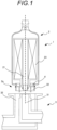
- FIG.1 shows a cross-sectional view of a container connection system 1.
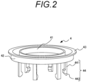
- FIG.2 shows an example of a connecting valve 4 which is one of the components of the container connection system 1.
- the container connection system 1 includes a fluid container 2, a container holder 3, and a connecting valve 4.
- FIG.3A is an enlarged view of the connecting portion between the fluid container 2 and the container holder 3 of the container connection system 1.
- the fluid container 2 is used to be removably connected to the container holder 3, and the container connection system 1 contributes to the connection.
- the direction in which the fluid container 2 is removably connected to the container holder 3 is defined as the connection direction.
- connection direction means the direction in which the fluid container 2 is removably connected to the container holder 3, and the axis of the direction is defined as the "connection axis.”
- the fluid container 2 is typically a container having a cavity in an elongated shape in the direction of the connection axis.
- the fluid container 2 is generally symmetrical about the connection axis, and is cylindrical in a representative example.
- a flow path structure is formed in the fluid container 2 so that fluid flows from upstream to downstream.
- the fluid container 2 has an inner conduit 21 and an outer conduit 22 through which fluid flows. Both the inner conduit 21 and the outer conduit 22 communicate with the flow path structure in the fluid container 2 to form a flow path. Either of the inner conduit 21 and the outer conduit 22 can be arranged upstream. That is, they form a flow path that flows from the inner conduit 21 through the inside of the container to the outer conduit 22, or conversely from the outer conduit 22 through the inside of the container to the inner conduit 21.
- the outer conduit 22 is formed outside the inner conduit 21, and the inner conduit 21 and the outer conduit 22 form a double conduit. That is, the inner conduit 21 is a closed region whose cross section is defined by the conduit wall of the inner conduit 21.
- the outer conduit 22 is defined by an outer surface 21a of the conduit wall of the inner conduit 21and an inner surface 22a of the outer conduit 22.
- the inner conduit 21 and the outer conduit 22 form a container connection 2a formed at one end of the fluid container 2.
- the container connection 2a can be defined such that the outer surface 22b of the outer conduit 22 forms an outer surface of the container connection 2a.
- a sealing material 2b such as an O-ring, is attached to the outer surface 22b of the outer conduit 22, which is the outer surface of the container connection 2a.
- the fluid container 2 can be a container generally used for a fluid system in which a fluid flows and used by detaching.
- a filter member 23 for filtering impurities and the like contained in the fluid can be stored in a channel structure in which the fluid flows in the fluid container 2.
- the fluid container 2 functions as a filter container.
- the container holder 3 has a structure for receiving the container connecting portion 2a, and is connected to the fluid container 2 when receiving the container connecting portion 2a.
- the container holder 3 has a conduit 31 connectable to the inner conduit 21 of the fluid container 2 and a conduit 32 connectable to the outer conduit 22 of the fluid container 2.
- the inner conduit 21 and the conduit 31 form a fluid connection in a state sealed from the outside
- the outer conduit 22 and the conduit 32 form a fluid connection in a state sealed from the outside.
- One of the conduit 31 and the conduit 32 is connected to a fluid source of fluid, and the other is connected to a discharge destination of fluid.
- a flow path is formed such that fluid flows from a conduit 31 to the inside of the container via an inner conduit 21 and flows out to a conduit 32 via an outer conduit 22, or fluid flows from a conduit 32 to the inside of the container via an outer conduit 22 and flows out to a conduit 31 via an inner conduit 21.
- the fluid container 2 has a connecting valve 4 therein.
- the body of the connecting valve 4 has an inner circumferential shape in the form of a hole or a notch in the central portion around the connection axis, and a surface along the circumference of the hole or a surface along the edge of the notch is defined as an inner sliding surface 41.
- the outer shape of the body of the connecting valve 4 has an outer circumferential shape, and a surface along the circumference thereof is defined as an outer sliding surface 42.
- the inner sliding 41 surface 41 has a shape corresponding to the cross section of the outer conduit 22 of the fluid container 2 perpendicular to the connection axis direction, and is freely movable so as to slide in the connection axis direction in close contact with the outer surface 21a of the inner conduit 21 of the fluid container 2.
- the cross section of the outer sliding surface 42 is a cross section of the outer circumferential surface of the connecting valve 4 perpendicular to the connection axis direction, has a shape corresponding to the cross section of the inner surface 22a of the outer conduit 22 of the fluid container 2 perpendicular to the connection axis direction, and can be moved so as to slide in the connection axis direction in close contact with the inner surface 22a of the outer conduit 22 of the fluid container 2.
- the container connecting portion 2a is arranged to extend in the connecting direction from the fluid container 2, and the inner conduit 21 and the outer conduit 22are also arranged to extend in the connecting direction from the fluid container 2.
- the connecting direction is set to be downward in the vertical direction. That is, when the fluid container 2 is connected to the container holder 3, the container connecting portion 2a is arranged to extend downward from the fluid container 2.
- the connecting valve 4 is positioned inside the container connecting portion 2a at any position on the outer surface 21a of the inner conduit 21 in a state of being closely fitted to the outer surface 21a of the inner conduit 21 of the fluid container 2. Since the inner sliding surface 41 of the connecting valve 4 is closely fitted to the outer surface 21a of the inner conduit 21, the connecting valve 4 is movable along the outer surface 21a of the inner conduit 21, but does not move in a state where there is no external force. In a state where the container connecting portion 2a of the fluid container 2 is separated from the container holder 3, the connecting valve 4 is typically lowered to the lowest position in the vertical direction as the connecting direction.
- the shape of the main body of the connecting valve 4 in a plane perpendicular to the connecting axis has a shape corresponding to the shape of the outer conduit 22 of the fluid container 2. Therefore, in this position, as will be described later, the inner sliding surface 41 of the connecting valve 4 is closely fitted to the outer surface 21a of the inner conduit 21 of the fluid container 2, and the outer sliding surface 42 of the connecting valve 4 is closely fitted to the inner surface 22a of the outer conduit 22 of the fluid container 2, so that the main body of the connecting valve 4 can close the outer conduit 22 of the fluid container 2 and block the flow of fluid.
- the connecting valve 4 has a first engaging portion 43 and a second engaging portion 44.
- the fluid container 2 has a seat 26 as a step on the inner surface 22a of the outer conduit 22 so as to extend from the inner surface 22a in the direction toward the connection shaft in the direction perpendicular to the connection shaft.
- the first engaging portion 43 abuts on the seat 26 to lock the connecting valve 4 so as not to fall out of the fluid container 2 and to hold the connecting valve 4.
- the first engaging portion 43 can be, for example, a tab arranged so as to extend from the outer peripheral shape of the connecting valve 4 in the direction perpendicular to the connection shaft.
- the second engaging portion 44 may comprise at least one flexible arm 441 extending from the main body of the connecting valve 4 in the direction of the connection axis, and a protrusion 442 disposed on the flexible arm 441.
- the flexible arm 441 can be flexibly deformed in the direction perpendicular to the connection axis by the elasticity of the material, and the position of the protrusion 442 can be moved in the direction perpendicular to the connection axis by the deformation of the flexible arm 441.
- the protrusion 442 has a chevron shape protruding from the surface of the flexible arm 441 in the direction perpendicular to the connection axis, and has a slope portion having a reduced height protruding from the most protruding portion in the direction of the connection axis.
- the container holder 3 has a groove that is a recess 33. Since the recess 33 is engaged with the protrusion 442 of the second engaging portion 44 of the connecting valve 4 when the fluid container 2 is connected to the container holder 3, the recess is arranged at a position where the protrusion 442 of the second engaging portion 44 is positioned when the fluid container 2 is connected to the container holder 3.
- the recess 33 can be arranged on the outer surface 31b of the conduit 31 after the protrusion 442 of the second engaging portion 44 is oriented in the direction of the center of the connection direction.
- the second engaging portion 44 can be arranged on the inner surface 32a of the conduit 32 in a reverse state in which the direction of the protrusion 442 is set to the outer direction opposite to the center direction of the connection direction (not shown).
- FIGS.1 and 3A to 3C how the container connection system 1 functions in the above-described structure and how the fluid container 2 is connected to the container holder 3 will be described.
- the container connecting portion 2a of the fluid container 2 is inserted into the container holder 3 in the connecting direction.
- FIG.3A shows the container connection system 1 when the fluid container 2 is separated from the container holder 3.
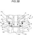
- FIG.3B shows the container connection system 1 immediately before the fluid container 2 is connected to the container holder 3.
- FIG.3C shows the container connection system 1 when the fluid container 2 is connected to the container holder 3.
- the container connecting portion 2a is in the downward direction and the connecting axis of the fluid container 2 is in the vertical direction. This state will be described below.
- the connecting valve 4 In a state in which the fluid container 2 is separated from the container holder 3, that is, in a state in which the fluid container 2 is handled independently, the connecting valve 4 is in a state in which it is lowered most downward in the vertical direction, which is the connection direction.
- the first engaging portion 43 of the connecting valve 4 is engaged to the seat 26 on the inner surface 22a of the outer conduit 22 of the fluid container 2, and the main body of the connecting valve 4 closes the outer conduit 22 (first position; FIG.3A ).
- the flexible arm 441 of the second engaging portion 44 extends in the connection direction.
- the inside of the fluid container 2 is isolated from the exterior by the connecting valve 4.
- the container connecting portion 2a of the fluid container 2 is inserted into the container holder 3.
- the flexible arm 441 of the second engaging portion 44 contacts the container holder 3 ( FIG.3B ).
- the contact position is not particularly limited as long as it is an arbitrary position of the container holder 3, but typically it can be set to contact the conduit 32 connected to the inner conduit 21 of the fluid container 2. From this state, the container connecting portion 2a is further inserted into the container holder 3.
- the connecting valve 4 As the container connecting portion 2a is inserted into the container holder 3, the connecting valve 4 is pushed up by the container holder 3, the inner sliding surface 41 of the connecting valve 4 is moved to slide along the outer surface 21a of the inner conduit 21, and the outer sliding surface 42 of the connecting valve 4 is moved to slide along the inner surface 22a of the outer conduit 22, thereby causing the connecting valve 4 to rise relative to the outer conduit 22.
- the flexible arm 441 expands in the direction perpendicular to the connecting direction (the radial direction of the container holder 3: the direction of arrow X) by elastic force, and the conduit 31 of the container holder 3 enters the flexible arm 441.
- the connecting valve 4 can move between the first position and the second position according to the state in which the fluid container 2 is connected to the container holder 3.
- the sealing member 2b of the outer conduit 22, which is the container connecting portion 2a of the fluid container 2 contacts and seals the inner surface of the conduit 32 of the container holder 3 so that the fluid does not leak.
- the inner conduit 21 of the container connecting portion 2a of the fluid container 2 is inserted into the container holder 3, and the sealing member 21b of the inner conduit 21 contacts and seals the inner surface 31a of the conduit 31 of the container holder 3 so that the fluid does not leak.
- the container connecting portion 2a of the fluid container 2 is removed from the container holder 3 in the connecting direction in the reverse of the procedure for connecting the fluid container 2 to the container holder 3.
- the container connecting portion 2a of the fluid container 2 also performs the reverse of the procedure for connecting the fluid container 2 to the container holder 3. That is, when the fluid container 2 is moved so as to remove the container connecting portion 2a from the container holder 3 in the connecting direction, since the protrusion 442 of the flexible arm 441 is engaged with the recess 33 of the container holder 3, the flexible arm 441 prevents the connecting valve 4 from moving with respect to the container holder 3, but the fluid container 2 is separated from the container holder 3.
- the connecting valve 4 relatively moves from the second position toward the first position with respect to the fluid container 2 in the fluid container 2.
- the protrusion 442 of the flexible arm 441 receives an external force from the fluid container 2 along the connecting direction so as to be released from the recess 33 of the container holder 3.
- the protrusion 442 of the flexible arm 441 moves in the direction in which the protrusion 442 is released from the recess 33 by the slope of the protrusion 442 of the flexible arm 441.
- the flexible arm 441 deforms by the elastic force so as to move away from the recess 33 in the direction perpendicular to the connecting direction (in the radial direction of the container holder 3: the direction of arrow X), and the protrusion 442 of the flexible arm 441 completely disengages from the recess 33.
- the flexible arm 441 returns to the lower position in the direction perpendicular to the connecting direction (in the radial direction of the container holder 3: the direction of arrow X) by the elastic force.
- the outer surface 21a of the inner conduit 21and the inner surface 22a of the outer conduit 22 of the fluid container 2 function as a guide portion for moving the connecting valve 4 between the first and second positions along the connection axis.
- the guide portion it is not always necessary for both the outer surface 21a of the inner conduit 21 and the inner surface 22a of the outer conduit 22 of the fluid container 2 to slide the connecting valve 4 in the direction of the connection axis.
- At least one of the outer surface 21a of the inner conduit 21and the inner surface 22a of the outer conduit 22 of the fluid container 2 can be configured to slide the connecting valve 4 in the direction of the connection axis.
- the inner sliding surface 41 of the connecting valve 4 can be partially configured to move along the outer surface 21a of the inner conduit 21 of the fluid container 2, and then the inner sliding surface 41 of the connecting valve 4 moves along the outer surface 21a of the inner conduit 21 of the fluid container 2 and the outer sliding surface 42 of the connecting valve 4 moves along the inner surface 22a of the outer conduit 22 of the fluid container 2.
- Such a configuration is also included as a function of the guide portion.
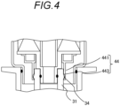
- the protrusion 442 of the second engaging portion 44 can be formed as a recess or a hole as the recess 443, and the recess 33 of the container holder 3 can be formed as a protrusion 34. Since the protrusion 34 is engaged with the recess 443 of the second engaging portion 44 of the connecting valve 4 when the fluid container 2 is connected to the container holder 3, the recess 443 of the second engaging portion 44 is arranged at a position when the fluid container 2 is connected to the container holder 3.
- the recess 443 may have a recess recessed from the surface of the flexible arm 441 in the vertical direction of the connection axis, and can be provided with a slope portion such that the depth of the recess protruding from the deepest recess along the direction of the connection axis is reduced.
- an exemplary embodiment has an inner sliding surface 41 of the connecting valve 4 and an outer sliding surface 42 of the connecting valve 4 as guide portions for moving the connecting valve 4 along the connection axis between the first position and the second position, wherein the connecting valve 4 is movable such that the inner sliding surface 41 of the connecting valve 4 is in close contact with the outer surface 21a of the inner conduit 21 of the fluid container 2 and the outer sliding surface 42 of the connecting valve 4 is in close contact with the inner surface 22a of the outer conduit 22 of the fluid container 2, and wherein the body of the connecting valve 4 closes the outer conduit 22 of the fluid container 2 to isolate the flow of fluid.
- the guide portion is not limited to the inner sliding surface 41 of the connecting valve 4 and the outer sliding surface 42 of the connecting valve 4.
- the guide portion can have various configurations as long as it causes the connecting valve to move between the first position and the second position.
- the guide portion can be an extension member 23a extending in the direction along the inner conduit, that is, in the direction of the connection axis.
- the connecting valve 4 described so far can be modified to form a connecting valve 5 engageable with the extension member 23a.
- the connecting valve 5 has a hole 51, and the connecting valve 5 is arranged so that the extension member 23a penetrates the hole 51.
- a seal member (not shown) for increasing the degree of adhesion can be arranged in either of the extension member 23a and the hole 51.
- the connecting valve 5 can move along the extension member 23a in the direction of the connection axis.
- the engagement between the connecting valve 5 and the extension member 23a is not limited to the formation of the hole 51 in the connecting valve 5, but also includes a mode in which a notch (not shown) is arranged in the connecting valve 5, and the notch (not shown) in the connecting valve 5 is engaged with the extension member 23a so as to be movable between the first position and the second position along the direction of the connection axis.
- the structure other than the guide portion is the same as that described above, and will be omitted here.
- FIG.5A shows the fluid container 2 and the container holder 3 spaced apart in this embodiment, with the connecting valve 5 in a first position to close the outer conduit 22.
- FIG.5B shows the fluid container 2 being received by the container holder 3, with the second engaging portion 54 of the connecting valve 5 in a second position to be engaged with the recess 33 of the container holder 3.
- the second engaging portion 54 of the connecting valve 5 functions in the same manner as the second engaging portion 44 of the connecting valve 4 described above.
- the connecting valve 5 may have an inclined surface 26a narrowing along the direction of the connection axis from the first position toward the second position with respect to the seat 26 of the fluid container 2 at the first position for closing the outer conduit 22.
- the tab of the connecting valve 5 can be configured as a complementary inclined surface having a contact surface 55 in contact with the inclined surface 26a of the seat when the container holder 3 receives the container connection 2a.
- a sealing member (not shown) for increasing the degree of adhesion can be arranged between the inclined surface 26a and the contact surface 55.
- the connecting valve 5 can close the outer conduit 22 at the first position for closing the outer conduit 22.
Landscapes
- Engineering & Computer Science (AREA)
- General Engineering & Computer Science (AREA)
- Mechanical Engineering (AREA)
- Chemical & Material Sciences (AREA)
- Chemical Kinetics & Catalysis (AREA)
- Physics & Mathematics (AREA)
- Geometry (AREA)
- Quick-Acting Or Multi-Walled Pipe Joints (AREA)
- Pipe Accessories (AREA)
- Physical Or Chemical Processes And Apparatus (AREA)
Applications Claiming Priority (2)
| Application Number | Priority Date | Filing Date | Title |
|---|---|---|---|
| JP2022000813A JP7763668B2 (ja) | 2022-01-06 | 2022-01-06 | 容器接続システムおよび流体容器 |
| PCT/JP2022/047090 WO2023132238A1 (ja) | 2022-01-06 | 2022-12-21 | 容器接続システムおよび流体容器 |
Publications (2)
| Publication Number | Publication Date |
|---|---|
| EP4462006A1 true EP4462006A1 (de) | 2024-11-13 |
| EP4462006A4 EP4462006A4 (de) | 2025-04-02 |
Family
ID=87073609
Family Applications (1)
| Application Number | Title | Priority Date | Filing Date |
|---|---|---|---|
| EP22918822.2A Pending EP4462006A4 (de) | 2022-01-06 | 2022-12-21 | Behälterverbindungssystem und flüssigkeitsbehälter |
Country Status (7)
| Country | Link |
|---|---|
| US (1) | US20250075836A1 (de) |
| EP (1) | EP4462006A4 (de) |
| JP (1) | JP7763668B2 (de) |
| KR (1) | KR20240134158A (de) |
| CN (1) | CN118525166A (de) |
| TW (1) | TW202344768A (de) |
| WO (1) | WO2023132238A1 (de) |
Families Citing this family (1)
| Publication number | Priority date | Publication date | Assignee | Title |
|---|---|---|---|---|
| DE102024119374A1 (de) | 2024-07-08 | 2026-01-08 | Mann+Hummel Gmbh | Filterelement und Filtersystem |
Family Cites Families (88)
| Publication number | Priority date | Publication date | Assignee | Title |
|---|---|---|---|---|
| US991568A (en) * | 1908-12-18 | 1911-05-09 | Otis W Hinckley | Apparatus for cooling and dispensing liquids. |
| US1019317A (en) * | 1911-03-16 | 1912-03-05 | Alfred E Goodwyn | Faucet. |
| US1006332A (en) * | 1911-03-30 | 1911-10-17 | Edward Dubbs Wilson | Combination bung and faucet. |
| US1241352A (en) * | 1915-02-23 | 1917-09-25 | Charles Doering Jr | Water-dispensing device. |
| US1732126A (en) * | 1928-08-28 | 1929-10-15 | Joseph P Gardner | Nursing bottle |
| US3387621A (en) * | 1965-07-21 | 1968-06-11 | Peter J. Schaff | Oil pan drain plug assembly |
| JPS453479B1 (de) * | 1966-08-24 | 1970-02-05 | ||
| US3785491A (en) * | 1971-10-28 | 1974-01-15 | Purolator Inc | Filter anti-drainback and relief valves |
| US3898414A (en) * | 1974-05-06 | 1975-08-05 | Dollinger Corp | Filter unit with cleaning attachment |
| JPS52144819A (en) * | 1976-04-27 | 1977-12-02 | Max Co Ltd | Coupling |
| US4657040A (en) * | 1985-11-25 | 1987-04-14 | Hr Textron Inc. | Bypass reverse flow valve |
| US4877521A (en) * | 1987-04-30 | 1989-10-31 | Cuno, Incorporated | Quick-change filter cartridge and head therefor |
| US4881568A (en) * | 1988-07-06 | 1989-11-21 | Ho I Chung | Irrigation chemical dispenser |
| US4907618A (en) * | 1988-07-06 | 1990-03-13 | Ho I Chung | Dispenser for irrigation chemicals |
| USRE33969E (en) * | 1988-07-27 | 1992-06-23 | The Coca-Cola Company | Binary syrup system bag and valve |
| US4862918A (en) * | 1988-08-29 | 1989-09-05 | Lancer Corporation | Valved connection apparatus |
| US4874023A (en) * | 1988-09-30 | 1989-10-17 | Liqui-Box Corporation | Decap dispensing system for water cooler bottles |
| US5031676A (en) * | 1988-09-30 | 1991-07-16 | Liqui-Box Corporation | Decap dispensing system for water cooler bottles |
| US4991635A (en) * | 1988-09-30 | 1991-02-12 | Liqui-Box Corporation | Decap dispensing system for water cooler bottles |
| US5129423A (en) * | 1990-03-16 | 1992-07-14 | Aeroquip Corporation | No-spill fluid security coupling |
| US5104003A (en) * | 1991-01-14 | 1992-04-14 | Stecoza Traian A | Cabonated beverage dispensing apparatus |
| GB9101560D0 (en) * | 1991-01-24 | 1991-03-06 | Boc Group Plc | Fluid delivery system |
| US5273083A (en) * | 1991-10-07 | 1993-12-28 | Ebtech, Inc. | Bottle cap and valve assembly for a bottled water station |
| US5413152C1 (en) * | 1991-10-07 | 2001-11-13 | Oasis Corp | Bottle cap and valve assembly for a bottled water station |
| US5370270A (en) * | 1991-10-08 | 1994-12-06 | Portola Packaging, Inc. | Non-spill bottle cap used with water dispensers |
| AU665216B2 (en) * | 1991-10-18 | 1995-12-21 | Royal Packaging Industries Van Leer B.V. | Fluid dispense system |
| JPH061985U (ja) * | 1992-06-15 | 1994-01-14 | サンデン株式会社 | ガスチャージコネクタ |
| US5468386A (en) * | 1993-03-19 | 1995-11-21 | Ing. Walter Hengst Gmbh & Co. Kg | Filter assembly and preassembled drain valve unit therefor |
| US5425404A (en) * | 1993-04-20 | 1995-06-20 | Minnesota Mining And Manufacturing Company | Gravity feed fluid dispensing system |
| JP3320176B2 (ja) * | 1993-11-30 | 2002-09-03 | 山信工業株式会社 | 液体用カプセル型フィルタ装置 |
| US5579953A (en) * | 1994-08-30 | 1996-12-03 | Plastic Systems Inc. | Liquid container and valve |
| US5556005A (en) * | 1995-01-09 | 1996-09-17 | Sprintvest Corporation Nv | Collapsible soap dispenser |
| US5591332A (en) * | 1995-05-25 | 1997-01-07 | Omnipure Filter Co. | Filter assembly with automatic shut-off and quick-connect filter cartridge |
| US5695168A (en) * | 1995-05-31 | 1997-12-09 | Williams; Richard T. | Automatic valving unit, and pressure vessel having automatic valving |
| US5628492A (en) * | 1996-02-02 | 1997-05-13 | Lee; Chung H. | Faucet connector device |
| US5753107A (en) * | 1996-08-08 | 1998-05-19 | Wtc Ecomaster Corporation | Dripless purification manifold and cartridge |
| FR2777967B1 (fr) * | 1998-04-28 | 2000-06-16 | Oreal | Organe d'activation d'une valve,valve equipee de cet organe et ensemble de distribution muni de cette valve |
| EP0972554B1 (de) * | 1998-07-17 | 2005-05-04 | Honda Giken Kogyo Kabushiki Kaisha | Filtervorrichtung |
| JP2000225305A (ja) | 1999-02-03 | 2000-08-15 | Nitto Kogyo Co Ltd | オイル処理用フィルタ |
| US6193113B1 (en) * | 1999-04-21 | 2001-02-27 | Douglas J. Hidding | Dispensing system with fluted probe and valved closure |
| US6234274B1 (en) * | 1999-04-23 | 2001-05-22 | K. J. Manufacturing, Inc. | Low profile nipple |
| US6637725B2 (en) * | 1999-06-04 | 2003-10-28 | Liqui-Box Corporation | Universal quick-disconnect coupling and valve |
| US20050000876A1 (en) * | 1999-12-03 | 2005-01-06 | Knight Steven R. | Keyed latch valve for fuel filter |
| US6953526B1 (en) * | 2000-03-22 | 2005-10-11 | Cuno Incorporated | Filter assembly |
| US6554139B1 (en) * | 2000-06-01 | 2003-04-29 | Parker-Hannifin Corporation | Extension and locking assembly for dripless element, and container therefore |
| US7374217B2 (en) * | 2001-09-28 | 2008-05-20 | Parker-Hannifin Corporation | Two way non leaking flow valve with full-open capability |
| JP4012408B2 (ja) * | 2002-02-12 | 2007-11-21 | 株式会社日立製作所 | オイルフィルタ |
| US6902669B2 (en) * | 2002-09-13 | 2005-06-07 | Fleetguard, Inc. | Filter cartridge with floating seal |
| JP3804949B2 (ja) * | 2002-11-12 | 2006-08-02 | トヨタ紡織株式会社 | 流体フィルタ及びそのドレン機構、流体フィルタに使用されるドレン用冶具並びに流体フィルタのドレン方法 |
| ITPD20030001A1 (it) * | 2003-01-03 | 2004-07-04 | Filmop Srl | Dispositivo perfezionato di collegamento e scollegamento |
| US7441664B2 (en) * | 2003-05-23 | 2008-10-28 | Pur Water Purification Products Inc. | Water treatment devices and cartridges therefor |
| NL1023520C2 (nl) * | 2003-05-23 | 2004-11-24 | Sgt Singapore Holdings Pte Ltd | Snelwisselfiltersysteem alsmede een basis en een snelwisselfilter bestemd voor een dergelijk systeem. |
| US8215492B2 (en) * | 2003-09-18 | 2012-07-10 | Pur Water Purification Products, Inc. | Water treatment devices and cartridges therefor |
| US6921003B2 (en) * | 2003-09-26 | 2005-07-26 | Charles Y. Yu | Water bottle cap |
| JP4190383B2 (ja) * | 2003-10-01 | 2008-12-03 | トヨタ紡織株式会社 | 流体フィルタ及びそのドレン機構、流体フィルタに使用されるドレン用冶具並びに流体フィルタのドレン方法 |
| US7141166B2 (en) * | 2003-10-10 | 2006-11-28 | Toyoda Boshoku Corporation | Drain structure having drainpipe and fluid filter using the same |
| JP2005299550A (ja) * | 2004-04-14 | 2005-10-27 | Hitachi Ltd | オイルフィルタ装置 |
| GB0415637D0 (en) * | 2004-07-13 | 2004-08-18 | Self Energising Coupling Compa | Coupling assembly |
| JP2006093001A (ja) * | 2004-09-27 | 2006-04-06 | Toshiba Corp | カプラ |
| US20090026400A1 (en) * | 2005-03-03 | 2009-01-29 | Maggie Chen | Modular Hose Coupler |
| US7387290B2 (en) * | 2005-08-05 | 2008-06-17 | Cheng-Chung Wang | Self locking air nozzle |
| US7690392B1 (en) * | 2006-03-03 | 2010-04-06 | Vahe Sarkiss | Cartridge and valve device for mixing effluent with liquid or solid using venturi |
| DE202006019003U1 (de) * | 2006-12-14 | 2008-05-21 | Mann + Hummel Gmbh | Flüssigkeitsabscheider, insbesondere Ölabscheider für Druckluftanlagen |
| US7867387B2 (en) * | 2007-07-19 | 2011-01-11 | Cummins Filtration Ip, Inc. | Standpipe with flow restriction valve, and filter cartridge |
| JP4924465B2 (ja) * | 2008-02-20 | 2012-04-25 | トヨタ紡織株式会社 | ドレン機構及びこれを備える流体フィルタ |
| GB0820981D0 (en) * | 2008-11-17 | 2008-12-24 | Reckitt & Colman Overseas | Dispenser and refill unit |
| US8920648B2 (en) * | 2009-02-25 | 2014-12-30 | Cummins Filtration Ip Inc. | No filter no run fluid filtration systems |
| US8776828B2 (en) * | 2009-07-20 | 2014-07-15 | Illinois Tool Works Inc. | Fluid dispensing assembly |
| EP2615044B1 (de) * | 2010-09-09 | 2017-12-20 | Mitani Valve Co., Ltd. | Betätiger für invertierten injektionsmechanismus mit konstantem volumen für aerosolartiges produkt |
| AU2011311175B2 (en) * | 2010-10-07 | 2016-06-30 | Amiad Water Systems Ltd. | Fluid filtering unit and system |
| FR2965887B1 (fr) * | 2010-10-08 | 2012-11-30 | Staubli Sa Ets | Dispositif de raccord avec verrouillage par griffes filetees et raccord comprenant un tel dispositif |
| WO2012122635A1 (en) * | 2011-03-16 | 2012-09-20 | Fuel Transfer Technologies, Inc. | Portable fluid container assembly, fluid connector and attachment |
| US9739367B2 (en) * | 2011-07-14 | 2017-08-22 | Oetiker Ny, Inc. | Transmission anti-leak valve |
| US8356794B1 (en) * | 2011-08-12 | 2013-01-22 | Liu Hsiu-Hsiung | Quick release connector |
| JP5668652B2 (ja) * | 2011-09-12 | 2015-02-12 | トヨタ自動車株式会社 | オイルフィルタ |
| US8632052B2 (en) * | 2012-01-20 | 2014-01-21 | Hsiu-Hsiung LIU | Quick release connector |
| US8641013B2 (en) * | 2012-06-07 | 2014-02-04 | Hsiu-Hsiung LIU | Quick release connector with a ring anti-drop cover |
| US9867730B2 (en) * | 2012-06-12 | 2018-01-16 | Flowsense Ltd. | Tubing valve and uses thereof |
| MX2016007250A (es) * | 2013-12-11 | 2017-07-19 | Quickflow Beverage Tech (Pty) Ltd | Aparato y sistema dispensador de fluidos. |
| DE102013021299A1 (de) * | 2013-12-19 | 2015-06-25 | Mann + Hummel Gmbh | Behandlungsvorrichtung zur Behandlung von insbesondere flüssigen Fluiden und Behandlungselement einer Behandlungsvorrichtung |
| CN108139744B (zh) | 2015-10-12 | 2021-07-06 | 费希尔-罗斯蒙特系统公司 | 用于调试断开连接的过程控制回路的部分的设备参数的自动分发 |
| CN110035813A (zh) * | 2016-10-03 | 2019-07-19 | 帕克-汉尼芬公司 | 带扭锁的过滤元件及组件 |
| US10975994B2 (en) * | 2018-01-16 | 2021-04-13 | Parker-Hannifin Corporation | Quick-coupling with internal slide locking mechanism |
| EP3520871B1 (de) * | 2018-01-31 | 2021-11-24 | Hengst SE | Filterkartusche und filterhalter für die filterkartusche |
| DE102019122882A1 (de) * | 2019-08-27 | 2021-03-04 | Hengst Se | Verschlusssystem für einen Flüssigkeitsfilter |
| JP7402710B2 (ja) | 2020-02-20 | 2023-12-21 | 日東工器株式会社 | 管継手部材および管継手 |
| US11821558B2 (en) * | 2021-09-08 | 2023-11-21 | Cooper-Standard Automotive Inc. | Fluid connector with dry break |
| CN217272655U (zh) * | 2022-03-25 | 2022-08-23 | 深圳市英维克智能连接技术有限公司 | 一种流体连接器及储能散热系统 |
-
2022
- 2022-01-06 JP JP2022000813A patent/JP7763668B2/ja active Active
- 2022-12-21 CN CN202280087736.XA patent/CN118525166A/zh active Pending
- 2022-12-21 WO PCT/JP2022/047090 patent/WO2023132238A1/ja not_active Ceased
- 2022-12-21 EP EP22918822.2A patent/EP4462006A4/de active Pending
- 2022-12-21 US US18/726,676 patent/US20250075836A1/en active Pending
- 2022-12-21 KR KR1020247026314A patent/KR20240134158A/ko active Pending
- 2022-12-26 TW TW111149919A patent/TW202344768A/zh unknown
Also Published As
| Publication number | Publication date |
|---|---|
| EP4462006A4 (de) | 2025-04-02 |
| CN118525166A (zh) | 2024-08-20 |
| KR20240134158A (ko) | 2024-09-06 |
| WO2023132238A1 (ja) | 2023-07-13 |
| JP7763668B2 (ja) | 2025-11-04 |
| JP2023100288A (ja) | 2023-07-19 |
| US20250075836A1 (en) | 2025-03-06 |
| TW202344768A (zh) | 2023-11-16 |
Similar Documents
| Publication | Publication Date | Title |
|---|---|---|
| US6488845B1 (en) | Oil filter unit with quick-drain valve actuator | |
| JP4327467B2 (ja) | 流体連通用の連結部材 | |
| US8967180B2 (en) | Pilot type pressure regulator | |
| US20250075836A1 (en) | Container connection system and fluid container | |
| US10682594B2 (en) | Filter element and fluid filter | |
| US12025085B2 (en) | Tank device | |
| RU2593328C2 (ru) | Топливный клапан | |
| US5681152A (en) | Membrane type fluid pump | |
| CN106794928B (zh) | 移液式容器 | |
| US12233364B2 (en) | Fuel filter cartridge with keyed profile | |
| EP3008353B1 (de) | Aktuatorbuchsen mit integrierten dichtungen | |
| JP2018016349A (ja) | 吐出キャップ | |
| CN107789875B (zh) | 用于流体过滤器的排放系统 | |
| US10712245B2 (en) | Filtration system for liquid samples | |
| EP2578821A1 (de) | Ölfilter und filterelement | |
| CN114173901A (zh) | 具有阀启动特征的滤筒 | |
| JP4726749B2 (ja) | オイルフィルタ | |
| US11280427B2 (en) | Vacuum safety valve | |
| EP4361487A1 (de) | Kupplungsvorrichtung | |
| CN111765241B (zh) | 密封装置和换挡系统 | |
| JP2024041402A (ja) | スポイト容器 | |
| US20160263496A1 (en) | Filter Element, in Particular for Liquid Filtration | |
| JP2006226300A (ja) | ガス放出防止装置 | |
| CN120322386A (zh) | 移液式容器 | |
| KR20230012754A (ko) | 다이어프램 밸브 |
Legal Events
| Date | Code | Title | Description |
|---|---|---|---|
| STAA | Information on the status of an ep patent application or granted ep patent |
Free format text: STATUS: THE INTERNATIONAL PUBLICATION HAS BEEN MADE |
|
| PUAI | Public reference made under article 153(3) epc to a published international application that has entered the european phase |
Free format text: ORIGINAL CODE: 0009012 |
|
| STAA | Information on the status of an ep patent application or granted ep patent |
Free format text: STATUS: REQUEST FOR EXAMINATION WAS MADE |
|
| 17P | Request for examination filed |
Effective date: 20240704 |
|
| AK | Designated contracting states |
Kind code of ref document: A1 Designated state(s): AL AT BE BG CH CY CZ DE DK EE ES FI FR GB GR HR HU IE IS IT LI LT LU LV MC ME MK MT NL NO PL PT RO RS SE SI SK SM TR |
|
| A4 | Supplementary search report drawn up and despatched |
Effective date: 20250227 |
|
| RIC1 | Information provided on ipc code assigned before grant |
Ipc: F16L 37/56 20060101ALI20250221BHEP Ipc: F16L 37/40 20060101ALI20250221BHEP Ipc: B01D 35/153 20060101ALI20250221BHEP Ipc: B01D 29/21 20060101ALI20250221BHEP Ipc: B01D 29/23 20060101ALI20250221BHEP Ipc: B01D 35/30 20060101ALI20250221BHEP Ipc: B01D 29/13 20060101ALI20250221BHEP Ipc: F16L 55/24 20060101ALI20250221BHEP Ipc: F16L 29/02 20060101ALI20250221BHEP Ipc: F16L 21/00 20060101ALI20250221BHEP Ipc: B01D 46/00 20220101ALI20250221BHEP Ipc: B01D 35/14 20060101ALI20250221BHEP Ipc: B01D 27/10 20060101ALI20250221BHEP Ipc: F16L 55/00 20060101AFI20250221BHEP |
|
| DAV | Request for validation of the european patent (deleted) | ||
| DAX | Request for extension of the european patent (deleted) | ||
| STAA | Information on the status of an ep patent application or granted ep patent |
Free format text: STATUS: EXAMINATION IS IN PROGRESS |
|
| 17Q | First examination report despatched |
Effective date: 20251008 |