EP4464602A2 - Déconnexions mécaniques pour voies de puissance parallèles dans des systèmes de propulsion électrique hybrides - Google Patents
Déconnexions mécaniques pour voies de puissance parallèles dans des systèmes de propulsion électrique hybrides Download PDFInfo
- Publication number
- EP4464602A2 EP4464602A2 EP24200909.0A EP24200909A EP4464602A2 EP 4464602 A2 EP4464602 A2 EP 4464602A2 EP 24200909 A EP24200909 A EP 24200909A EP 4464602 A2 EP4464602 A2 EP 4464602A2
- Authority
- EP
- European Patent Office
- Prior art keywords
- shaft
- heat engine
- turbine
- electric motor
- compressor
- Prior art date
- Legal status (The legal status is an assumption and is not a legal conclusion. Google has not performed a legal analysis and makes no representation as to the accuracy of the status listed.)
- Pending
Links
Images



Classifications
-
- B—PERFORMING OPERATIONS; TRANSPORTING
- B64—AIRCRAFT; AVIATION; COSMONAUTICS
- B64D—EQUIPMENT FOR FITTING IN OR TO AIRCRAFT; FLIGHT SUITS; PARACHUTES; ARRANGEMENT OR MOUNTING OF POWER PLANTS OR PROPULSION TRANSMISSIONS IN AIRCRAFT
- B64D27/00—Arrangement or mounting of power plants in aircraft; Aircraft characterised by the type or position of power plants
- B64D27/02—Aircraft characterised by the type or position of power plants
- B64D27/10—Aircraft characterised by the type or position of power plants of gas-turbine type
-
- B—PERFORMING OPERATIONS; TRANSPORTING
- B64—AIRCRAFT; AVIATION; COSMONAUTICS
- B64D—EQUIPMENT FOR FITTING IN OR TO AIRCRAFT; FLIGHT SUITS; PARACHUTES; ARRANGEMENT OR MOUNTING OF POWER PLANTS OR PROPULSION TRANSMISSIONS IN AIRCRAFT
- B64D27/00—Arrangement or mounting of power plants in aircraft; Aircraft characterised by the type or position of power plants
- B64D27/02—Aircraft characterised by the type or position of power plants
- B64D27/04—Aircraft characterised by the type or position of power plants of piston type
-
- B—PERFORMING OPERATIONS; TRANSPORTING
- B64—AIRCRAFT; AVIATION; COSMONAUTICS
- B64D—EQUIPMENT FOR FITTING IN OR TO AIRCRAFT; FLIGHT SUITS; PARACHUTES; ARRANGEMENT OR MOUNTING OF POWER PLANTS OR PROPULSION TRANSMISSIONS IN AIRCRAFT
- B64D27/00—Arrangement or mounting of power plants in aircraft; Aircraft characterised by the type or position of power plants
- B64D27/02—Aircraft characterised by the type or position of power plants
- B64D27/30—Aircraft characterised by electric power plants
- B64D27/33—Hybrid electric aircraft
-
- B—PERFORMING OPERATIONS; TRANSPORTING
- B64—AIRCRAFT; AVIATION; COSMONAUTICS
- B64D—EQUIPMENT FOR FITTING IN OR TO AIRCRAFT; FLIGHT SUITS; PARACHUTES; ARRANGEMENT OR MOUNTING OF POWER PLANTS OR PROPULSION TRANSMISSIONS IN AIRCRAFT
- B64D35/00—Transmitting power from power plants to propellers or rotors; Arrangements of transmissions
- B64D35/02—Transmitting power from power plants to propellers or rotors; Arrangements of transmissions specially adapted for specific power plants
- B64D35/021—Transmitting power from power plants to propellers or rotors; Arrangements of transmissions specially adapted for specific power plants for electric power plants
- B64D35/022—Transmitting power from power plants to propellers or rotors; Arrangements of transmissions specially adapted for specific power plants for electric power plants of hybrid-electric type
- B64D35/023—Transmitting power from power plants to propellers or rotors; Arrangements of transmissions specially adapted for specific power plants for electric power plants of hybrid-electric type of series-parallel type
-
- B—PERFORMING OPERATIONS; TRANSPORTING
- B64—AIRCRAFT; AVIATION; COSMONAUTICS
- B64D—EQUIPMENT FOR FITTING IN OR TO AIRCRAFT; FLIGHT SUITS; PARACHUTES; ARRANGEMENT OR MOUNTING OF POWER PLANTS OR PROPULSION TRANSMISSIONS IN AIRCRAFT
- B64D35/00—Transmitting power from power plants to propellers or rotors; Arrangements of transmissions
- B64D35/02—Transmitting power from power plants to propellers or rotors; Arrangements of transmissions specially adapted for specific power plants
- B64D35/021—Transmitting power from power plants to propellers or rotors; Arrangements of transmissions specially adapted for specific power plants for electric power plants
- B64D35/022—Transmitting power from power plants to propellers or rotors; Arrangements of transmissions specially adapted for specific power plants for electric power plants of hybrid-electric type
- B64D35/024—Transmitting power from power plants to propellers or rotors; Arrangements of transmissions specially adapted for specific power plants for electric power plants of hybrid-electric type of series type
-
- B—PERFORMING OPERATIONS; TRANSPORTING
- B64—AIRCRAFT; AVIATION; COSMONAUTICS
- B64D—EQUIPMENT FOR FITTING IN OR TO AIRCRAFT; FLIGHT SUITS; PARACHUTES; ARRANGEMENT OR MOUNTING OF POWER PLANTS OR PROPULSION TRANSMISSIONS IN AIRCRAFT
- B64D35/00—Transmitting power from power plants to propellers or rotors; Arrangements of transmissions
- B64D35/02—Transmitting power from power plants to propellers or rotors; Arrangements of transmissions specially adapted for specific power plants
- B64D35/021—Transmitting power from power plants to propellers or rotors; Arrangements of transmissions specially adapted for specific power plants for electric power plants
- B64D35/022—Transmitting power from power plants to propellers or rotors; Arrangements of transmissions specially adapted for specific power plants for electric power plants of hybrid-electric type
- B64D35/025—Transmitting power from power plants to propellers or rotors; Arrangements of transmissions specially adapted for specific power plants for electric power plants of hybrid-electric type of parallel type
-
- F—MECHANICAL ENGINEERING; LIGHTING; HEATING; WEAPONS; BLASTING
- F02—COMBUSTION ENGINES; HOT-GAS OR COMBUSTION-PRODUCT ENGINE PLANTS
- F02B—INTERNAL-COMBUSTION PISTON ENGINES; COMBUSTION ENGINES IN GENERAL
- F02B41/00—Engines characterised by special means for improving conversion of heat or pressure energy into mechanical power
- F02B41/02—Engines with prolonged expansion
- F02B41/10—Engines with prolonged expansion in exhaust turbines
-
- F—MECHANICAL ENGINEERING; LIGHTING; HEATING; WEAPONS; BLASTING
- F02—COMBUSTION ENGINES; HOT-GAS OR COMBUSTION-PRODUCT ENGINE PLANTS
- F02C—GAS-TURBINE PLANTS; AIR INTAKES FOR JET-PROPULSION PLANTS; CONTROLLING FUEL SUPPLY IN AIR-BREATHING JET-PROPULSION PLANTS
- F02C7/00—Features, components parts, details or accessories, not provided for in, or of interest apart form groups F02C1/00 - F02C6/00; Air intakes for jet-propulsion plants
- F02C7/36—Power transmission arrangements between the different shafts of the gas turbine plant, or between the gas-turbine plant and the power user
-
- B—PERFORMING OPERATIONS; TRANSPORTING
- B64—AIRCRAFT; AVIATION; COSMONAUTICS
- B64D—EQUIPMENT FOR FITTING IN OR TO AIRCRAFT; FLIGHT SUITS; PARACHUTES; ARRANGEMENT OR MOUNTING OF POWER PLANTS OR PROPULSION TRANSMISSIONS IN AIRCRAFT
- B64D27/00—Arrangement or mounting of power plants in aircraft; Aircraft characterised by the type or position of power plants
- B64D27/02—Aircraft characterised by the type or position of power plants
- B64D27/026—Aircraft characterised by the type or position of power plants comprising different types of power plants, e.g. combination of a piston engine and a gas-turbine
-
- B—PERFORMING OPERATIONS; TRANSPORTING
- B64—AIRCRAFT; AVIATION; COSMONAUTICS
- B64D—EQUIPMENT FOR FITTING IN OR TO AIRCRAFT; FLIGHT SUITS; PARACHUTES; ARRANGEMENT OR MOUNTING OF POWER PLANTS OR PROPULSION TRANSMISSIONS IN AIRCRAFT
- B64D27/00—Arrangement or mounting of power plants in aircraft; Aircraft characterised by the type or position of power plants
- B64D27/02—Aircraft characterised by the type or position of power plants
- B64D27/30—Aircraft characterised by electric power plants
- B64D27/35—Arrangements for on-board electric energy production, distribution, recovery or storage
- B64D27/351—Arrangements for on-board electric energy production, distribution, recovery or storage using energy recovery
-
- B—PERFORMING OPERATIONS; TRANSPORTING
- B64—AIRCRAFT; AVIATION; COSMONAUTICS
- B64D—EQUIPMENT FOR FITTING IN OR TO AIRCRAFT; FLIGHT SUITS; PARACHUTES; ARRANGEMENT OR MOUNTING OF POWER PLANTS OR PROPULSION TRANSMISSIONS IN AIRCRAFT
- B64D27/00—Arrangement or mounting of power plants in aircraft; Aircraft characterised by the type or position of power plants
- B64D27/02—Aircraft characterised by the type or position of power plants
- B64D27/30—Aircraft characterised by electric power plants
- B64D27/35—Arrangements for on-board electric energy production, distribution, recovery or storage
- B64D27/357—Arrangements for on-board electric energy production, distribution, recovery or storage using batteries
-
- F—MECHANICAL ENGINEERING; LIGHTING; HEATING; WEAPONS; BLASTING
- F01—MACHINES OR ENGINES IN GENERAL; ENGINE PLANTS IN GENERAL; STEAM ENGINES
- F01D—NON-POSITIVE DISPLACEMENT MACHINES OR ENGINES, e.g. STEAM TURBINES
- F01D15/00—Adaptations of machines or engines for special use; Combinations of engines with devices driven thereby
- F01D15/10—Adaptations for driving, or combinations with, electric generators
-
- F—MECHANICAL ENGINEERING; LIGHTING; HEATING; WEAPONS; BLASTING
- F02—COMBUSTION ENGINES; HOT-GAS OR COMBUSTION-PRODUCT ENGINE PLANTS
- F02B—INTERNAL-COMBUSTION PISTON ENGINES; COMBUSTION ENGINES IN GENERAL
- F02B37/00—Engines characterised by provision of pumps driven at least for part of the time by exhaust
- F02B37/04—Engines with exhaust drive and other drive of pumps, e.g. with exhaust-driven pump and mechanically-driven second pump
- F02B37/10—Engines with exhaust drive and other drive of pumps, e.g. with exhaust-driven pump and mechanically-driven second pump at least one pump being alternatively or simultaneously driven by exhaust and other drive, e.g. by pressurised fluid from a reservoir or an engine-driven pump
- F02B37/105—Engines with exhaust drive and other drive of pumps, e.g. with exhaust-driven pump and mechanically-driven second pump at least one pump being alternatively or simultaneously driven by exhaust and other drive, e.g. by pressurised fluid from a reservoir or an engine-driven pump exhaust drive and pump being both connected through gearing to engine-driven shaft
-
- Y—GENERAL TAGGING OF NEW TECHNOLOGICAL DEVELOPMENTS; GENERAL TAGGING OF CROSS-SECTIONAL TECHNOLOGIES SPANNING OVER SEVERAL SECTIONS OF THE IPC; TECHNICAL SUBJECTS COVERED BY FORMER USPC CROSS-REFERENCE ART COLLECTIONS [XRACs] AND DIGESTS
- Y02—TECHNOLOGIES OR APPLICATIONS FOR MITIGATION OR ADAPTATION AGAINST CLIMATE CHANGE
- Y02T—CLIMATE CHANGE MITIGATION TECHNOLOGIES RELATED TO TRANSPORTATION
- Y02T50/00—Aeronautics or air transport
- Y02T50/60—Efficient propulsion technologies, e.g. for aircraft
Definitions
- the present disclosure relates to aircraft engines, and more particularly to hybrid aircraft engines.
- Aircraft engines vary in efficiency and function over a plurality of parameters, such as thrust requirements, air temperature, air speed, altitude, and the like. Aircraft require the most thrust at take-off, wherein the demand for engine power is the heaviest. However, during the remainder of the mission, the aircraft engines often do not require as much thrust as during take-off. The size and weight of the engines allows them to produce the power needed for take-off, however after take-off the engines are in effect over-sized for the relatively low power required to produce thrust for cruising in level flight.
- a hybrid propulsion system includes a heat engine configured to drive a heat engine shaft.
- An electric motor is configured to drive a motor shaft.
- a transmission system includes at least one gear box. The transmission system is configured to receive rotational input power from each of the heat engine shaft and the motor shaft and to convert the rotation input power to output power.
- the motor shaft includes a disconnect mechanism to allow the heat engine to rotate with the electric motor stopped.
- the heat engine shaft includes a disconnect mechanism to allow the electric motor to rotate with the heat engine stopped.
- the at least one gearbox can include a combining gear box connecting to the heat engine shaft and to the motor shaft to combine rotational input power from the heat engine and electric motor for providing rotational output power to an output shaft.
- the at least one gearbox can also include a turbine gear box.
- the turbine gear box can be connected between the heat engine shaft and a shaft for driving a turbine and a compressor to drive the turbine and compressor at a different rotational speed from the heat engine.
- the disconnect mechanism of the motor shaft can be located between the combining gear box and the electric motor.
- the disconnect mechanism of the heat engine shaft can be located between the combining gear box and the heat engine.
- the heat engine shaft and motor shaft can be concentric.
- the at least one gear box can include a reduction gear box connected to each of the heat engine shaft and the motor shaft.
- the heat engine shaft can connect to a turbine shaft for driving a turbine and compressor.
- the disconnect mechanism of the motor shaft can be located between the electric motor and the reduction gear box.
- the disconnect mechanism of the heat engine shaft can be located between the heat engine and the electric motor.
- the heat engine shaft can run through the motor shaft and through the disconnect mechanism of the motor shaft. It is also contemplated that the heat engine shaft and the motor shaft can be combined as a single common shaft connected to the transmission system.
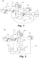
- Fig. 1 a partial view of an exemplary embodiment of a hybrid propulsion system in accordance with the disclosure is shown in Fig. 1 and is designated generally by reference character 100.
- Other embodiments of hybrid propulsion systems in accordance with the disclosure, or aspects thereof, are provided in Figs. 2-17 , as will be described.
- the systems and methods described herein can be used to provide hybrid propulsion, e.g., for improving fuel efficiency in aircraft.
- the hybrid propulsion system 100 includes a heat engine (or motor) 102 configured to drive a heat engine shaft 104.
- An electric motor 106 is configured to drive an electric motor shaft 108.
- a transmission system 110 includes at least one gearbox. The transmission system 110 is configured to receive rotational input power from each of the heat engine shaft 104 and the motor shaft 108 and to convert the rotation input power to output power, as indicated by the circular arrow in Fig. 1 .
- the at least one gearbox includes a combining gearbox 112 connecting to the heat engine shaft 104 and to the motor shaft 108 to combine rotational input power from the heat engine 102 and electric motor 106 for providing rotational output power to an output shaft 114, which can drive a reduction gearbox 116 for turning an aircraft propeller, fan, or any other suitable type of air mover for example.
- a turbine gearbox 118 is included, which is connected between the heat engine shaft 104 and a shaft 120 for driving a turbine 122 and a compressor 124 to drive the turbine 122 and compressor 124 at a different rotational speed from the heat engine 102.
- the heat engine 102 can run at 8000 revolutions per minute (RPM), the heat engines exhaust can be recovered by the turbine 122 to drive the compressor 120 at 35,000 RPM.
- the turbine gearbox 118 can be a two speed transmission or constant velocity transmission (CVT) which can eliminate the need for a variable inlet guide vane (VIGV) controlling the compressor 124.
- VGV variable inlet guide vane
- the turbine 122 and compressor 124 can separately connect to the turbine gear box 118, e.g., using a concentric shaft for the compressor such as the shaft 1246 shown in Fig. 14 , so that the turbine 122 and compressor 124 can rotate at different rotational speeds.
- These types of turbine gearbox can apply to each of the turbine gearboxes described below, even if not specifically repeated.
- the compressor 120 compresses air and supplies the compressed air to the heat engine 102 through the air line 126, which includes heat exchanger 128 for cooling the compressed air. After combustion in the heat engine 102, the combustion products are supplied through a combustion products line 130 to the turbine 122, which extracts power from the compressed combustion products before exhausting them.
- the configurations shown in Figs. 2-15 also include similar air lines 126, heat exchangers 128, and combustion products lines 130, and the details for such are not repeated below for each Figure. Also, unless specified otherwise, the configurations in each of Figs. 2-15 include an output shaft 114 connecting between a combining gearbox (e.g. combining gearbox 112) and reduction gearbox 116, the details of which will not be repeated below for each Figure.
- the electric motor 106 can be powered to boost horse power, e.g., for take-off, in parallel with the heat motor 102, and can be powered down, e.g., for cruising in level flight, where only the heat motor 102 is needed for power. It is also contemplated that the electric motor 106 can be used as a generator to recharge the battery, e.g. source 1138 of Fig. 13 , when power is available from the heat engine 102 or form wind milling the propeller to drive the reduction gear box 116.
- the compressor 124 and turbine 122 improve the thermal efficiency of the heat engine 102. Similar benefits are derived with the configurations described below with respect to Figs. 2-15 .
- FIG. 1 schematically indicates that the turbine 122 can optionally be moved to connect directly to the combining gearbox 112, much as described below with respect to Fig. 13 , which switch in turbine position can also be applied to other arrangements described below wherein the compressor and turbine are shown and described as being on a common shaft.
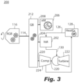
- a system 200 includes a combining gearbox 212 connecting to the heat engine shaft 204, the motor shaft 208, and a shaft 220 for driving the turbine 222 and compressor 224.
- the combining gearbox 212 combines rotational input power from the heat engine (or motor) 202 and electric motor 206 for providing rotational output power to an output shaft 114 and to drive the turbine 222 and compressor 224. While connected on a common shaft 220, the turbine 222 and compressor 224 can be connected on opposite sides of the combining gearbox 212 as shown in Fig. 2 . It is also contemplated that the turbine 222 and compressor 224 can both be connected on one side of the combining gearbox 212, as shown in Fig. 3 .
- the portion of the combining gearbox 212 that drives the shaft 220 can be a two speed transmission or constant velocity transmission (CVT) which can eliminate the need for a variable inlet guide vane (VIGV) controlling the compressor 224.
- CVT constant velocity transmission
- VIGV variable inlet guide vane
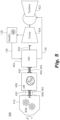
- a system 300 is shown wherein the heat engine shaft 304 and the electric motor shaft 308 are connected for common rotation.
- a reduction gearbox 316 e.g. for ultimately outputting power to a propeller, is connected to a common output shaft 305 of the electric motor 306 and the heat engine 302.
- a turbine gearbox 332 is connected between the heat engine shaft 304 and a shaft 320 for rotation of the turbine 322 and compressor 324 at a different rotational speed from the heat engine 302 and electric motor 306.
- the broken line in Fig. 4 indicates that the position of the heat engine 302 and electric motor 306 can be reversed on the common shaft 305.
- each of the heat engine 302 and electric motor can be connected to the reduction gearbox 316 through a concentric shaft, e.g. as indicated by the broken lines between the electric motor 306 and the reduction gear box 316.
- a concentric shaft e.g. as indicated by the broken lines between the electric motor 306 and the reduction gear box 316.
- the heat engine shaft 404 and electric motor shaft 408 are concentric with a shaft 420 for rotation of the turbine 422 and compressor 424.
- the heat engine shaft 404 and electric motor shaft 408 can be a common shaft 405 as shown in Fig. 5 , or can themselves be concentric with one another as indicated by the broken lines in Fig. 5 .
- a reduction gearbox 416 is connected to each of the heat engine shaft 404 and the electric motor shaft 408, e.g., for driving a propeller with rotational input from the heat engine 402 and electric motor 406.
- the reduction gearbox 416 connects to a shaft 420 for rotation of the turbine 422 and compressor 424.
- a system 500 has a heat engine shaft 504 and the electric motor shaft 508 connected for common rotation.
- a combining gearbox 512 connects to the common output shaft 505 of the electric motor 506 and the heat engine 502 and a shaft 520 for driving a turbine 522 and compressor 524, to combine rotational input power from the heat engine 502 and electric motor 506 for providing rotational output power to an output shaft 114 and to drive the turbine 522 and compressor 524.
- the turbine 522 and compressor 524 are connected on opposite sides of the combining gearbox 512. As shown in Fig. 7 , it is also contemplated that the turbine 522 and compressor 524 can both be on one side of the combining gearbox 512.
- the broken lines in Figs. 6 and 7 schematically indicate that the positions of the heat motor 502 and electric motor 506 can be switched.
- a system 600 includes a combining gearbox 612 connecting to the heat engine shaft 604 and to the electric motor shaft 608 to combine rotational input power from the heat engine 602 and electric motor 606 for providing rotational output power to an output shaft 114.
- a turbine driver motor/generator 634 is connected to a shaft 620 for driving a turbine 622 and a compressor 624 to drive the turbine 622 and compressor 624 at a different rotational speed ratio from the heat engine 602 and electric motor 606.
- the compressor 624 can therefore be a variable speed compressor.
- An electrical system 636 includes a storage 638, e.g., a battery, battery bank, capacitor, capacitor bank, super capacitor or super capacitor bank, flywheel or flywheel bank, or the like, is connected to a first inverter/rectifier component 640 for supplying power from the storage 638 to drive the electric motor 606 or in an energy recovery mode, to store into the storage 638 energy generated by driving the electric motor 606 in a generator mode.
- the electrical system 636 includes a second invert/rectifier component 642 for supplying power to drive the turbine driver motor 634, or to recover energy into the storage 638 from the turbine drive motor 634 if run in a generator mode.
- the broken line in Fig. 8 schematically indicates that the position of the motor 634 and compressor can be switched on the shaft 620.
- Figs. 9 , 10 , 11 , and 12 each show similar electrical systems 636 and the description thereof is not repeated below.
- a system 700 has the heat engine shaft 704 and the electric motor shaft 108 are connected for common rotation.
- a reduction gearbox 716 connected to a common output shaft 714 of the electric motor 706 and the heat engine 702.
- a turbine driver motor 734 is connected to a shaft 720 for driving a turbine 722 and a compressor 724 at a different rotational speed from the heat engine 702 and electric motor 706.
- the broken arrows in Fig. 9 schematically indicate that the position of the heat engine 702 and the electric motor 706 can be switched on the common shaft 714, and that the positions of the motor 734 and compressor 724 can be switched on the shaft 720.
- the heat engine shaft 804 and the electric motor shaft 808 are connected for common rotation.
- a reduction gearbox 816 is connected to a common output shaft 814 of the electric motor 806 and the heat engine 802.
- a turbine gearbox 818 is connected through a clutch 844 between the heat engine shaft 804 and a shaft 820 for driving a turbine 822 and a compressor 824 at a different rotational speed ratio from the heat engine 802 and electric motor 802 when the clutch 844 is engaged.
- the shaft 820 for driving the turbine 822 and compressor 824 is connected to a turbine driver motor 834 to drive the turbine 822 and compressor 824 independently from the heat engine 802 and electric motor 806 when the clutch 844 is disengaged.
- the clutch 844 can prevent electrical losses at steady state because the clutch engages when system 800 steady state operation, e.g., cruising in level flight, so the shaft 820 is connected to the heat engine 802 to avoid electrical conversion losses. In transients, the clutch 844 can open or disconnect to allow the motor 834 to drive the shaft 820 at a different speed ratio from the heat engine 802 as described above.
- a system 900 includes a heat engine shaft 904 and electric motor shaft 908 that are concentric with the shaft 20 for rotation of the turbine 922 and compressor 924 similar to the arrangement in Fig. 5 .
- a reduction gearbox 916 is connected to each of the heat engine shaft 904 and the electric motor shaft 908, e.g., as a common shaft 905 or concentric with one another as described above with respect to Fig. 5 .
- a clutch 944 in the shaft 920 connects between the heat engine 902 and a turbine driver motor 934 for rotating the turbine 922 and compressor 924 with the reduction gear box 916 when the clutch 944 is engaged, and to drive the turbine 922 and compressor 924 independently from the heat engine 902 and electric motor 906 when the clutch 944 is disengaged.
- a system 1000 includes a heat engine shaft 1004 and electric motor shaft 1008 are connected for common rotation.
- a reduction gearbox 1016 is connected to a common output shaft 1014 of the electric motor 1006 and the heat engine 1002.
- the upper broken lines in Fig. 12 schematically indicate that the positions of the heat engine 1002 and the motor 1006 can be switched on the shaft 1014.
- a clutch 1044 connects between the reduction gearbox 1016 and a turbine driver motor 1034 connected to a shaft 1020 for driving a turbine 1022 and a compressor 1024 with rotational power from the heat engine 1002 and electric motor 1002 (through the reduction gearbox 1016) when the clutch 1044 is engaged, and to drive the turbine 1022 and compressor 1024 independently from the heat engine 1002 and electric motor 1006 when the clutch 1044 is disengaged.
- the lower broken line in Fig. 12 schematically indicates that the positions of the motor 1034 and the compressor 1024 can be switched on the shaft 1020.
- a system 1100 is shown wherein the heat engine shaft 1104 and the electric motor shaft 1108 are connected for common rotation.
- a combining gearbox 1112 connects to a common output shaft 1105 of the electric motor 1106 and the heat engine 1102, and to a shaft 1114 of a turbine 1122 to combine rotational input power from the heat engine 1102, electric motor 1106, and turbine 1122 for providing rotational output power to an output shaft 1114.
- a reduction gearbox 1116 is connected to the output shaft 1114, wherein a compressor 1124 is connected to be driven on the output shaft 1114.
- An electrical system 1136 includes a storage 1138 connected through an inverter/rectifier component 1140 to supply power to the motor 1106, or to recover power from the motor 1106 in a generator mode to store in the storage 1138.
- the other arrangements described above that do not specifically show an electrical system can include a system similar to electrical system 1136, and Fig. 14 includes a similar system 1136 even though the details are not repeated.
- the compressor 1124 can also be connected to the reduction gearbox 1116 on its own shaft concentric with the shaft 1114, much as described below with respect to Fig. 14 .
- the turbine 1122 can be mechanically decoupled from the CGB to drive a generator 1134, which can be connected through an inverter/rectifier component 1142 to charge the storage 1138, which can similarly be applied to other arrangements disclosed herein with the turbine decoupled from the compressor.
- the compressor and a gear box 1118 can be connected to the heat engine 1102 in lieu of connecting the compressor 1124 on the output shaft 1114.
- a system 1200 is shown wherein the heat engine shaft 1204 and the electric motor shaft 1208 are connected for common rotation.
- a reduction gearbox 1216 connected to a common output shaft 1214 of the electric motor 1206 and the heat engine 1202.
- a turbine gearbox 1218 is connected between the heat engine shaft 1204 and a shaft 1220 of a turbine 1222 so the turbine can rotate at a different rotational speed from the heat engine 1202 and electric motor 1206.
- a compressor 1224 is connected to the reduction gearbox 1216 through a compressor shaft 1246 concentric with the common output shaft 1214 so the compressor can be driven at a different speed from the common output shaft 1214.
- a system 1300 includes a heat engine shaft 1304 and the electric motor shaft 1308 that are connected for common rotation.
- a super position gearbox 1316 connects to a common output shaft 1314 of the electric motor 1306 and the heat engine 1302, and to a shaft 1320 for driving a turbine 1322 and compressor 1324 to combine rotational input power from the heat engine 1302 and electric motor 1306 for providing rotational output power to an output shaft 1314 and to drive the turbine 1322 and compressor 1324.
- the super position gearbox 1316 is configured so the speed ratio between the common output shaft 1314 and the shaft 1320 for driving the turbine 1322 and compressor 1324 can vary, e.g., to adjust the speed of the compressor 1324 for altitude or for ground idle.
- the turbine 1322 can optionally be decoupled from the compressor 1324 to drive a generator as described above with reference to Fig. 13 .
- the arrangement in Fig. 3 can be modified so the turbine 222 is decoupled from the compressor 224 to drive a generator.
- the heat engine e.g., heat engine 202 in Fig. 2
- each of the shafts 104 and 108 can be included, e.g., in each of the shafts 104 and 108 as indicated in Fig. 1 by the broken lines crossing the shafts 104 and 108, for disconnecting the heat engine 102 or electric motor 106 as needed.
- This can also be applied to other embodiments disclosed above besides the arrangement in Fig. 1 .
- modules are represented schematically herein vertically on top of each other, those skilled in the art having the benefit of this discourse will readily appreciate that they can be located side by side, one above the other or in any geometrical arrangement and in any order in physical implementations.
- modules represented on one side (right or left) of the respective gearbox herein can also potentially be installed on the other side or even trapped between a respecting reduction gearbox and combining gear box.
- Module disclosed herein can be installed directly on the respective combining gear box or reduction gear box with a proper speed ratio.
- modules are represented herein with an axial orientation
- bevel gears or other mechanical or electrical devices
- accessories not explicitly represented herein can be included and can potentially be connected mechanically to any module or driven electrically similar to the modules and components disclosed herein.
- combining gearboxes and reduction gearboxes disclosed above can be combined into a single respective gearbox.
- the hybrid propulsion system 100 includes a heat engine 102 configured to drive a heat engine shaft 104.
- An electric motor 106 is configured to drive a motor shaft 108.
- a transmission system 110 includes at least one gear box. The transmission system 110 is configured to receive rotational input power from each of the heat engine shaft 104 and the motor shaft 108 and to convert the rotation input power to output power, as indicated by the circular arrow in Fig. 16 .
- the at least one gearbox includes a combining gear box 112 connecting to the heat engine shaft 104 and to the motor shaft 108 to combine rotational input power from the heat engine 102 and electric motor 106 for providing rotational output power to an output shaft 114, which can drive a reduction gear box 116 for turning an aircraft propeller, fan, or any other suitable type of air mover for example.
- a turbine gear box 118 is included, which is connected between the heat engine shaft 104 and a shaft 120 for driving a turbine 122 and a compressor 124 to drive the turbine 122 and compressor 124 at a different rotational speed from the heat engine 102.
- the heat engine 102 can run at 8000 revolutions per minute (RPM) to drive the turbine 122 and compressor 124 at 35,000 RPM.
- RPM revolutions per minute
- the turbine 122 can actually add power to the shaft 120 and therefore cooperates with the heat engine 102 to drive the compressor 124, however, in configurations herein where the turbine 122 and compressor 124 spin at a common speed the compressor 124 and turbine 122 are collectively referred to herein as driven.
- the compressor 124 compresses air and supplies the compressed air to the heat engine 102 through the air line 126, which includes heat exchanger 128 for cooling the compressed air. After combustion in the heat engine 102, the combustion products are supplied through a combustion products line 130 to the turbine 122, which extracts power from the compressed combustion products before exhausting them.
- the configuration shown in Fig. 17 also includes similar connections air lines 126, heat exchangers 128, and combustion products lines 130, and the details for such are not repeated below.
- the electric motor 106 can be powered to boost horse power, e.g., for take-off, in parallel with the heat motor 102, and can be powered down, e.g., for cruising in level flight, where only the heat motor 102 is needed for power.
- the compressor 124 and turbine 122 improve the thermal efficiency of the heat engine 102. Similar benefits are derived with the configuration described below with respect to Fig. 17 .
- the motor shaft 108 includes a disconnect mechanism 144, such as a clutch or the like, to allow the heat engine 102 to rotate with the electric motor 106 stopped.
- the heat engine shaft 104 includes a disconnect mechanism 146, e.g., a clutch or the like, to allow the electric motor 106 to rotate with the heat engine 102 stopped.
- the disconnect mechanism 144 of the motor shaft 108 is located between the combining gear box 112 and the electric motor 106, or may be combined into the combining gear box 112.
- the disconnect mechanism 146 of the heat engine shaft 104 is located between the combining gear box 112 and the heat engine 102, or may be combined into the combining gear box 112. For example, in the event that the electric motor needs to stop rotating, the disconnect mechanism 144 can be disengaged.
- the disconnect mechanism 146 can disengage to mechanically disconnect the heat engine 102 from the transmission system 110 so that at least some power can still be provided through the electric motor 106.
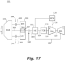
- the heat engine shaft 304 and motor shaft 308 are concentric.
- a reduction gear box 316 is connected to each of the heat engine shaft 304 and the motor shaft 308, e.g., for driving a propeller with rotational input from the heat engine 302 and electric motor 306.
- the heat engine shaft 304 connects to a turbine shaft 320 through a turbine gear box 318 for driving a turbine 322 and compressor 324 for driving the turbine shaft 320 at a different speed from the heat engine shaft 304.
- the turbine gear box 318 can be omitted by directly connecting the turbine shaft 320 to the heat engine shaft 304 for common rotation or to the reduction gearbox 316 (or to a combining gearbox 112 shown in Fig. 16 ).
- the heat motor 302 can drive the turbine 322 and compressor 324 at the same rotational speed as the heat motor 302. Regardless of whether the turbine gear box 318 is included, the heat engine 302 can rotate at a different rotational speed from the electric motor 306.
- the disconnect mechanism 344 of the motor shaft 308 is located between the electric motor 306 and the reduction gear box 316.
- the disconnect mechanism 346 of the heat engine shaft 308 is located between the heat engine 302 and the electric motor 306.
- the disconnect mechanism 346 can also be located in any suitable location along the shaft 304.
- Disconnect mechanisms 344 and 346 can be clutches or any other suitable type of disconnect mechanisms.
- the heat engine shaft 304 runs through the motor shaft 308 and through the disconnect mechanism 344 of the motor shaft 308.
- the disconnect mechanisms 344 and 346 can disconnect as needed to allow for stoppages of one of the heat engine 302 or electric motor 306 with at least some guaranteed power output to the reduction gearbox 316 of from the working one of the heat engine 302 or electric motor 306 much as described above with respect to Fig. 16 .
- heat engine shaft 304 and the motor shaft 308 can be combined as a single common shaft, e.g., by mounting the rotor of the electric motor 306 to the heat engine shaft 304, which is connected to the reduction gearbox 316.
- the electric motor could be independently disconnected by a clutch 347 between the rotor 349 and the heat engine shaft 304, as indicated by broken lines in Fig. 17 .
- the clutches and disconnect mechanisms disclosed herein can be configured for repeated, at will connection and disconnection. It is also contemplated that the clutches and disconnect mechanisms disclosed herein can be configured for one disconnect only. Those skilled in the art will readily appreciate that while disconnect mechanism are described above for systems 100 and 300, the disconnect mechanisms disclosed herein can readily be applied to any of the systems disclosed herein without departing from the scope of this disclosure.
Landscapes
- Engineering & Computer Science (AREA)
- Mechanical Engineering (AREA)
- Aviation & Aerospace Engineering (AREA)
- Chemical & Material Sciences (AREA)
- Combustion & Propulsion (AREA)
- General Engineering & Computer Science (AREA)
- Engine Equipment That Uses Special Cycles (AREA)
- Hybrid Electric Vehicles (AREA)
- Transmission Devices (AREA)
- Arrangement Of Transmissions (AREA)
Applications Claiming Priority (4)
| Application Number | Priority Date | Filing Date | Title |
|---|---|---|---|
| US201962812474P | 2019-03-01 | 2019-03-01 | |
| US201962820064P | 2019-03-18 | 2019-03-18 | |
| PCT/US2019/065449 WO2020180380A1 (fr) | 2019-03-01 | 2019-12-10 | Déconnexions mécaniques pour voies de puissance parallèles dans des systèmes de propulsion électrique hybrides |
| EP19917818.7A EP3931101B1 (fr) | 2019-03-01 | 2019-12-10 | Déconnexions mécaniques pour voies de puissance parallèles dans des systèmes de propulsion électrique hybrides |
Related Parent Applications (1)
| Application Number | Title | Priority Date | Filing Date |
|---|---|---|---|
| EP19917818.7A Division EP3931101B1 (fr) | 2019-03-01 | 2019-12-10 | Déconnexions mécaniques pour voies de puissance parallèles dans des systèmes de propulsion électrique hybrides |
Publications (2)
| Publication Number | Publication Date |
|---|---|
| EP4464602A2 true EP4464602A2 (fr) | 2024-11-20 |
| EP4464602A3 EP4464602A3 (fr) | 2025-02-26 |
Family
ID=72337266
Family Applications (2)
| Application Number | Title | Priority Date | Filing Date |
|---|---|---|---|
| EP19917818.7A Active EP3931101B1 (fr) | 2019-03-01 | 2019-12-10 | Déconnexions mécaniques pour voies de puissance parallèles dans des systèmes de propulsion électrique hybrides |
| EP24200909.0A Pending EP4464602A3 (fr) | 2019-03-01 | 2019-12-10 | Déconnexions mécaniques pour voies de puissance parallèles dans des systèmes de propulsion électrique hybrides |
Family Applications Before (1)
| Application Number | Title | Priority Date | Filing Date |
|---|---|---|---|
| EP19917818.7A Active EP3931101B1 (fr) | 2019-03-01 | 2019-12-10 | Déconnexions mécaniques pour voies de puissance parallèles dans des systèmes de propulsion électrique hybrides |
Country Status (4)
| Country | Link |
|---|---|
| US (2) | US11732639B2 (fr) |
| EP (2) | EP3931101B1 (fr) |
| CA (1) | CA3131966A1 (fr) |
| WO (1) | WO2020180380A1 (fr) |
Families Citing this family (11)
| Publication number | Priority date | Publication date | Assignee | Title |
|---|---|---|---|---|
| GB201918281D0 (en) * | 2019-12-12 | 2020-01-29 | Rolls Royce Plc | Aircraft hybrid propulsion system |
| US11794917B2 (en) * | 2020-05-15 | 2023-10-24 | Pratt & Whitney Canada Corp. | Parallel control loops for hybrid electric aircraft |
| US20230257128A1 (en) * | 2022-02-11 | 2023-08-17 | Pratt & Whitney Canada Corp. | Hybrid-Electric Aircraft Propulsion System and Method for Operating the Same |
| FR3133175B1 (fr) * | 2022-03-03 | 2024-03-01 | Safran Helicopter Engines | Ensemble propulsif amélioré pour aéronef hybridé multi moteurs |
| EP4310309B1 (fr) * | 2022-07-19 | 2026-04-22 | General Electric Company | Système de propulsion hybride-électrique équipé d'un coupleur pour commuter entre des modes de fonctionnement |
| US12145738B2 (en) * | 2022-08-22 | 2024-11-19 | Pratt & Whitney Canada Corp. | Multi-drive unit propulsion system for an aircraft |
| US20240328363A1 (en) * | 2023-03-31 | 2024-10-03 | Pratt & Whitney Canada Corp. | Power coupling between engine rotating assembly and external device |
| DE102023206915A1 (de) * | 2023-07-20 | 2025-01-23 | kopter germany GmbH | Antriebssystem für einen Drehflügler |
| KR20250081978A (ko) * | 2023-11-28 | 2025-06-09 | 한국항공우주연구원 | 다중 동력원 전기추진시스템을 구비한 비행체 |
| US20250242928A1 (en) * | 2024-01-26 | 2025-07-31 | Pratt & Whitney Canada Corp. | Hybrid aircraft power plant and gearbox therefor |
| DE102024121114A1 (de) | 2024-07-24 | 2026-01-29 | Rolls-Royce Deutschland Ltd & Co Kg | Hybrides Antriebssystem für ein Flugzeug |
Family Cites Families (237)
| Publication number | Priority date | Publication date | Assignee | Title |
|---|---|---|---|---|
| US4815282A (en) * | 1987-02-24 | 1989-03-28 | Teledyne Industries, Inc. | Turbocharged compund cycle ducted fan engine system |
| IT1297108B1 (it) | 1997-12-10 | 1999-08-03 | Franco Capanna | Sistema per la trasformazione di un aeromobile a decollo e volo orizzontale autosostentato in aeromobile integrato, ibrido a decollo |
| US9506405B2 (en) | 1998-04-03 | 2016-11-29 | Rockwell Collins Control Technologies, Inc. | Apparatus and method for controlling power generation system |
| DE19817333C5 (de) | 1998-04-18 | 2007-04-26 | Conti Temic Microelectronic Gmbh | Elektrische Antriebseinheit aus Elektromotor und Elektronikmodul |
| DE19923201A1 (de) | 1999-05-20 | 2000-11-23 | Mannesmann Vdo Ag | Für einen Einsatz in einem aggressiven Medium vorgesehener Einsatz |
| US6179072B1 (en) | 1999-10-13 | 2001-01-30 | Deere & Company | Supplemental charge for hydrostatic steering system |
| DE10000110B4 (de) | 2000-01-04 | 2004-06-24 | Sauer-Sundstrand Gmbh & Co. | Hydrostatischer Fahrzeugantrieb mit Steuerungseinrichtung und Steuerungseinrichtung für hydrostatische Antriebe |
| US6537047B2 (en) | 2000-02-15 | 2003-03-25 | Frank H. Walker | Reversible variable displacement hydraulic pump and motor |
| DE10132303B4 (de) | 2001-07-06 | 2006-04-13 | Sew-Eurodrive Gmbh & Co. Kg | Baureihe von Planetengetrieben, Planetenträger für eine Baureihe von Planetengetrieben und Antrieb |
| US6692395B2 (en) | 2002-02-25 | 2004-02-17 | Deere & Company | Transmisson for power take-off |
| US20030171184A1 (en) | 2002-03-11 | 2003-09-11 | Russell Wige | Dual-input differential planetary gear transmission |
| DK1509695T3 (da) | 2002-05-16 | 2008-11-10 | Mlh Global Corp Inc | Vindmölle med hydraulisk transmission |
| US9776715B2 (en) | 2002-10-01 | 2017-10-03 | Andrew H B Zhou | Amphibious vertical takeoff and landing unmanned device |
| US7150340B2 (en) | 2003-02-21 | 2006-12-19 | Lockheed Martin Corporation | Hub drive and method of using same |
| US7011600B2 (en) | 2003-02-28 | 2006-03-14 | Fallbrook Technologies Inc. | Continuously variable transmission |
| US7022042B2 (en) | 2004-01-27 | 2006-04-04 | Yakov Fleytman | Epicyclic gear train |
| ES2275370B1 (es) | 2004-03-05 | 2008-05-01 | Industria Helicat Y Alas Giratorias, S.L. | Metodo de operacion de una aeronave convertible. |
| US7093789B2 (en) | 2004-05-24 | 2006-08-22 | The Boeing Company | Delta-winged hybrid airship |
| US7089744B2 (en) | 2004-07-21 | 2006-08-15 | Steward Davis International, Inc. | Onboard supplemental power system at varying high altitudes |
| US7111462B2 (en) | 2004-07-21 | 2006-09-26 | Steward-Davis International, Inc. | Onboard supplemental power system at varying high altitudes |
| US7098569B2 (en) | 2004-07-30 | 2006-08-29 | Ballard Power Systems Corporation | Rotor assembly for a permanent magnet power electric machine |
| US7247967B2 (en) | 2004-08-09 | 2007-07-24 | A. O. Smith Corporation | Electric motor having a stator |
| US7118340B2 (en) | 2004-09-10 | 2006-10-10 | Sikorsky Aircraft Corporation | Swashplate and pitch link arrangement for a coaxial counter rotating rotor system |
| US7398946B1 (en) | 2004-10-04 | 2008-07-15 | United States Of America As Represented By The Secretary Of The Air Force | Power line sentry charging |
| JP4715161B2 (ja) | 2004-10-26 | 2011-07-06 | アイシン・エィ・ダブリュ株式会社 | プラネタリギヤ装置 |
| US7503173B2 (en) | 2005-02-08 | 2009-03-17 | Parker-Hannifin Corporation | Control devices for swashplate type variable displacement piston pump |
| JP2006231974A (ja) | 2005-02-22 | 2006-09-07 | Shimadzu Corp | 航空機の空気調和装置 |
| JP4215012B2 (ja) | 2005-03-15 | 2009-01-28 | トヨタ自動車株式会社 | ハイブリッド車およびその制御方法 |
| JP2006270778A (ja) | 2005-03-25 | 2006-10-05 | Denso Corp | 車載無線通信機 |
| JP2006290187A (ja) | 2005-04-12 | 2006-10-26 | Nissan Motor Co Ltd | 車両用ハイブリッド駆動装置 |
| US7380749B2 (en) | 2005-04-21 | 2008-06-03 | The Boeing Company | Combined fuel cell aircraft auxiliary power unit and environmental control system |
| US7345398B2 (en) | 2005-06-20 | 2008-03-18 | Kurz-Kasch, Inc. | Electric motor stator |
| KR20070039699A (ko) | 2005-10-10 | 2007-04-13 | 박명구 | 복합연속기능 다중 동력 전달장치 |
| DE102005062347A1 (de) | 2005-12-23 | 2007-06-28 | Eurocopter Deutschland Gmbh | Hochdehnbares Energie- und/oder Signalübertragungskabel sowie Rotorblatt mit einem derartigen Kabel |
| JP4321530B2 (ja) | 2006-01-27 | 2009-08-26 | トヨタ自動車株式会社 | 車両およびその制御方法 |
| JP4680075B2 (ja) | 2006-02-01 | 2011-05-11 | トヨタ自動車株式会社 | 動力出力装置およびこれを搭載する車両並びに動力出力装置の制御装置、動力出力装置の制御方法 |
| US7921945B2 (en) | 2006-02-21 | 2011-04-12 | Clean Emissions Technologies, Inc. | Vehicular switching, including switching traction modes and shifting gears while in electric traction mode |
| US7471026B2 (en) | 2006-03-13 | 2008-12-30 | Isca Innovatons, Llc | Brushless electric motor |
| MX2008013496A (es) | 2006-04-18 | 2009-03-31 | Interdigital Tech Corp | Metodo y aparato para implementar h-arq en un sistema de comunicacion inalambrica mimo. |
| US9976437B2 (en) | 2006-08-15 | 2018-05-22 | United Technologies Corporation | Epicyclic gear train |
| US7513224B2 (en) | 2006-09-11 | 2009-04-07 | The Scuderi Group, Llc | Split-cycle aircraft engine |
| US7867122B2 (en) | 2006-09-26 | 2011-01-11 | Epi-Energy Ltd. | Power transmission system with continuously variable speed control |
| EP2069619A2 (fr) | 2006-10-05 | 2009-06-17 | Mitja Victor Hinderks | Machines alternatives améliorées |
| US7984684B2 (en) | 2006-10-06 | 2011-07-26 | Mitja Victor Hinderks | Marine hulls and drives |
| DE102006056356A1 (de) | 2006-11-29 | 2008-06-05 | Airbus Deutschland Gmbh | Antriebsvorrichtung mit mehreren Energiewandlern für ein Flugzeug |
| US7762770B2 (en) | 2006-12-14 | 2010-07-27 | Sikorsky Aircraft Corporation | Hybrid actuator for helicopter rotor blade control flaps |
| WO2008075127A1 (fr) * | 2006-12-19 | 2008-06-26 | Renault Trucks | Groupe moto-propulseur pour véhicule automobile et véhicule comprenant un tel groupe moto-propulseur |
| KR101205076B1 (ko) | 2007-02-09 | 2012-11-27 | 란세스 도이치란트 게엠베하 | 혼성 구조의 경량 요소 |
| JP4973256B2 (ja) | 2007-03-15 | 2012-07-11 | トヨタ自動車株式会社 | 車両およびその制御方法 |
| US7978635B2 (en) | 2007-03-21 | 2011-07-12 | Qualcomm Incorporated | H-ARQ acknowledgment detection validation by re-decoding |
| KR100871432B1 (ko) | 2007-03-23 | 2008-12-15 | (주)하이게인안테나 | 저고도 레이더 안테나 |
| KR20080005377U (ko) | 2007-05-09 | 2008-11-13 | 서원영 | 자가 발전을 이용한 자동 충전 시스템. |
| BRMU8701724U2 (pt) | 2007-10-19 | 2009-06-09 | Alfredo Pintarelli | sistema gerador de energia por autorotação em aeronaves de asas rotativas |
| WO2009057082A2 (fr) | 2007-11-01 | 2009-05-07 | Ducere Holdings (Pty) Limited | Dispositif d'entraînement à mécanisme hydraulique à boucle ouverte pouvant fonctionner comme pompe ou comme moteur |
| US7827787B2 (en) | 2007-12-27 | 2010-11-09 | Deere & Company | Hydraulic system |
| US20110030503A1 (en) | 2008-01-07 | 2011-02-10 | Bell Helicopter Textron Inc. | Transmission housing assembly having improved bearing liner |
| DE102008008236A1 (de) | 2008-02-08 | 2009-08-13 | Markus Liebherr International Ag | Hydrostatisch leistungsverzweigtes Getriebe |
| JP5167062B2 (ja) | 2008-03-12 | 2013-03-21 | 株式会社日本自動車部品総合研究所 | エンジン制御装置 |
| CN107084036B (zh) | 2008-04-16 | 2019-10-22 | 米提亚·维克托·辛德克斯 | 新型往复式机器和其它装置 |
| DE102009019994B4 (de) | 2008-05-19 | 2020-08-13 | Airbus Operations Gmbh | Flugzeug mit Hybrid Transmittern zur kontaktlosen Energie-und Datenübertragung |
| GB2460237A (en) | 2008-05-20 | 2009-11-25 | Torotrak Dev Ltd | Vehicle kinetic energy recovery system |
| US7958725B2 (en) | 2008-05-21 | 2011-06-14 | Caterpillar Inc. | Drivetrain system having simultaneous displacement control |
| US8747267B2 (en) | 2008-07-10 | 2014-06-10 | Rochester Institute Of Technology | Gear-based continuously variable transmission systems and methods thereof |
| DE102008034607A1 (de) | 2008-07-25 | 2010-01-28 | Voith Patent Gmbh | Überlagerungsgetriebe mit Kopplungswellen |
| IT1391708B1 (it) | 2008-09-11 | 2012-01-27 | Tampieri | Riduttore epicicloidale a planetarie equilibrate. |
| DE102008050801A1 (de) | 2008-10-08 | 2010-04-15 | Pro Diskus Ag | Rotor-Welle-Anordnung für eine elektrische Maschine |
| DE102009019485A1 (de) | 2008-12-09 | 2010-06-10 | Isatec Gmbh | Antriebsstrang mit einem ersten Elektromotor und einem Planetengetriebe sowie Windenergieanlagen, Gasturbinen und Wasserturbinen und Fahrzeuge, die diesen Antriebsstrang aufweisen |
| JP5299679B2 (ja) | 2009-02-06 | 2013-09-25 | 株式会社デンソー | モータジェネレータ |
| GB0903423D0 (en) | 2009-03-02 | 2009-04-08 | Rolls Royce Plc | Variable drive gas turbine engine |
| MA31733B1 (fr) | 2009-03-17 | 2010-10-01 | Halieurop | Pêcherie hybride multimodale integree aux petits pelagiques |
| US8495870B2 (en) | 2009-03-19 | 2013-07-30 | Kubota Corporation | Work machine |
| US8471429B2 (en) | 2009-04-07 | 2013-06-25 | GM Global Technology Operations LLC | Isolator ring for an electric motor |
| US8395274B2 (en) | 2009-04-15 | 2013-03-12 | Hamilton Sundstrand Corporation | Integrated power unit as energy storage device for electrical power system |
| US8596054B2 (en) | 2009-05-01 | 2013-12-03 | Atlas Copco Drilling Solutions, Inc. | Absorber-replenisher in a hydrostatic circuit |
| US8622859B2 (en) | 2009-06-10 | 2014-01-07 | Czero Holding Company, Llc | Systems and methods for hybridization of a motor vehicle using hydraulic components |
| WO2011024928A1 (fr) | 2009-08-24 | 2011-03-03 | Kawanishi Eiji | Générateur d'électricité hybride accouplé à un générateur d'électricité à gravité qui utilise une bascule comportant un dispositif de charge de pression |
| US8584452B2 (en) | 2009-09-04 | 2013-11-19 | Lloydco Llc | Infinitely-variable, hydro-mechanical transmission using fixed displacement pumps and motors |
| GB0916387D0 (en) | 2009-09-18 | 2009-10-28 | New And Renewable Energy Ct Ltd | A power collection and distribution system |
| KR20110032973A (ko) | 2009-09-24 | 2011-03-30 | 최억만 | 풍속(風速)발전(發電)장치(裝置)와 배터리 교환 방식(하 이브리드 카(用) |
| US8943820B2 (en) | 2009-12-09 | 2015-02-03 | Caterpillar Inc. | Method for controlling a pump and motor system |
| DE102010000909B4 (de) | 2010-01-14 | 2017-06-22 | Airbus Operations Gmbh | Vorrichtung zum Bereitstellen von Radiofrequenzsignalverbindungen |
| KR20110087661A (ko) | 2010-01-27 | 2011-08-03 | 박경섭 | 그린에너지 하이브리드 헬리콥터 |
| FR2957207B1 (fr) | 2010-03-05 | 2016-01-22 | Pascal Chretien | Groupe electromoteur distribue. |
| US20110215584A1 (en) | 2010-03-08 | 2011-09-08 | Brennan Mikael Prokopich | Air / wind tunnel powered turbine, electric power recharging system |
| US8641379B2 (en) | 2010-03-24 | 2014-02-04 | Hamilton Sundstrand Corporation | Hybrid ram air turbine |
| US8521032B2 (en) | 2010-04-01 | 2013-08-27 | The Boeing Company | Optical fiber interface system and connector |
| US8816632B2 (en) | 2010-04-28 | 2014-08-26 | Lockheed Martin Corporation | Radio frequency power transmission system |
| US8535197B2 (en) | 2010-05-12 | 2013-09-17 | Enerflex Ltd. | Speed changer assembly |
| DE112010005569A5 (de) | 2010-05-17 | 2013-04-25 | Hyon Engineering Gmbh | Brennkraftmaschine |
| FR2962404B1 (fr) | 2010-07-08 | 2012-07-20 | Eurocopter France | Architecture electrique pour aeronef a voilure tournante a motorisation hybride |
| FR2964948B1 (fr) | 2010-09-16 | 2012-08-31 | Eurocopter France | Aeronef a voilure tournante muni d'un moyen propulsif, et procede applique par ledit aeronef |
| US8621860B2 (en) | 2010-10-22 | 2014-01-07 | Cnh America Llc | Control system for work vehicle |
| US9033273B2 (en) | 2010-11-02 | 2015-05-19 | Jonathan Edelson | Integrated aircraft ground navigation control system |
| US8446121B1 (en) | 2010-11-19 | 2013-05-21 | The Boeing Company | High performance actuator motor |
| US8739533B2 (en) | 2010-12-02 | 2014-06-03 | Or Yogev | Solar augmented wind turbine for stable and dispatchable utility scale power generation |
| US9343939B2 (en) | 2010-12-23 | 2016-05-17 | General Electric Company | Electric motor structure to minimize electro-magnetic interference |
| KR101936448B1 (ko) | 2011-03-31 | 2019-01-08 | 가부시끼 가이샤 구보다 | 변속 전동 장치 및 주행 전동 장치 |
| FR2979614B1 (fr) | 2011-09-04 | 2013-09-20 | Eric Chantriaux | Transmission electromagnetique de puissance pour aeronef a voilure tournante ou fixe. |
| US8531076B2 (en) | 2011-05-17 | 2013-09-10 | GM Global Technology Operations LLC | Stator for an electric motor |
| DE102011078775B4 (de) | 2011-07-07 | 2019-12-24 | Schaeffler Technologies AG & Co. KG | Differenzialanordnung mit einem Differenzial und einem Planetengetriebe |
| DE102011107403B4 (de) | 2011-07-07 | 2013-01-17 | Astrium Gmbh | Radarsystem mit synthetischer Apertur |
| ES2398316B1 (es) | 2011-07-18 | 2014-04-29 | Airbus Operations, S.L. | Sistema versátil de potencia en aeronaves |
| EP2551198B1 (fr) | 2011-07-29 | 2013-11-13 | AGUSTAWESTLAND S.p.A. | Avion convertible |
| JP2014524549A (ja) | 2011-08-12 | 2014-09-22 | イートン コーポレーション | 慣性エネルギーを回生するための方法及び装置 |
| CN103748365B (zh) | 2011-08-24 | 2016-09-07 | 株式会社小松制作所 | 液压驱动系统 |
| FR2979615B1 (fr) | 2011-09-04 | 2013-09-20 | Eric Chantriaux | Aeronef equipe d'un groupe electromoteur distribue a roues libres. |
| FR2980771B1 (fr) | 2011-09-29 | 2014-10-31 | Eurocopter France | Aeronef hybride a voilure tournante |
| US9096230B2 (en) | 2011-11-01 | 2015-08-04 | Caterpillar Paving Products Inc. | Hystat drive system having coasting functionality |
| WO2013074430A1 (fr) | 2011-11-14 | 2013-05-23 | Cnh America Llc | Transmission à variation continue hydromécanique pour produire un couple de sortie élevé |
| KR101277645B1 (ko) | 2011-11-14 | 2013-06-21 | 인하대학교 산학협력단 | 태양광 및 풍력을 이용한 하이브리드 발전기 |
| DE102011118550B4 (de) | 2011-11-16 | 2019-07-04 | Diehl Aviation Laupheim Gmbh | Gepäckablagefach für ein Flugzeug und Flugzeug mit dem Gepäckablagefach |
| US8660761B2 (en) | 2011-11-23 | 2014-02-25 | Caterpillar Inc. | Method of effecting simultaneous displacement changes in hydrostatic drive machine |
| BRPI1104839A2 (pt) | 2011-11-25 | 2012-11-20 | Barros Marcelo Monteiro De | turbina eàlica de energia para veÍculos elÉtricos e hÍbridos |
| DE102011087712A1 (de) | 2011-12-05 | 2013-06-06 | Schaeffler Technologies AG & Co. KG | Planetenwälzgewindetrieb |
| KR101975062B1 (ko) | 2011-12-27 | 2019-05-03 | 두산인프라코어 주식회사 | 건설기계의 유압시스템 |
| US9233748B2 (en) | 2012-01-04 | 2016-01-12 | James William McIntee | Roadable, adaptable-modular, multiphibious-amphibious ground effect or flying, car-boat-plane or surface-effect motorcycle |
| US9102326B2 (en) * | 2012-03-05 | 2015-08-11 | Embry-Riddle Aeronautical University, Inc. | Hybrid assembly for an aircraft |
| US9066249B2 (en) | 2012-03-07 | 2015-06-23 | Apple Inc. | Methods and apparatus for interference coordinated transmission and reception in wireless networks |
| JP2013193533A (ja) | 2012-03-19 | 2013-09-30 | Toyota Motor Corp | ハイブリッド車 |
| JP5867219B2 (ja) | 2012-03-23 | 2016-02-24 | トヨタ自動車株式会社 | ハイブリッド車両 |
| EP2657519B1 (fr) | 2012-04-26 | 2015-06-17 | Siemens Aktiengesellschaft | Éolienne |
| US10119414B2 (en) | 2012-05-08 | 2018-11-06 | David J. Podrog | Hafnium turbine engine and method of operation |
| DE102012209807A1 (de) | 2012-06-12 | 2013-12-12 | Siemens Aktiengesellschaft | Flugzeug und Verfahren zum Herstellen eines Flugzeugs |
| KR101497604B1 (ko) | 2012-06-19 | 2015-03-03 | 주식회사 엘지화학 | 전력 운송 시스템 및 이를 이용한 전력 운송 방법 |
| ITTO20120565A1 (it) | 2012-06-26 | 2013-12-27 | Oerlikon Graziano Spa | Trasmissione ibrida per veicolo a motore |
| CA2820254C (fr) | 2012-07-09 | 2020-02-18 | Mcmaster University | Systeme de groupe propulseur hybride |
| FR2993727B1 (fr) | 2012-07-19 | 2017-07-21 | Eurocopter France | Machine electrique reversible pour aeronef |
| US9458864B2 (en) | 2012-07-25 | 2016-10-04 | The Ritsumeikan Trust | Hydraulic drive circuit |
| EP2690007B1 (fr) | 2012-07-26 | 2016-08-31 | Airbus Operations GmbH | Procédé de production d'énergie hydraulique dans un aéronef, utilisation d'une unité de commande d'énergie hybride et d'un système d'entraînement |
| FR2994687B1 (fr) | 2012-08-27 | 2014-07-25 | Eurocopter France | Procede d'assistance d'un pilote d'un aeronef monomoteur a voilure tournante lors d'une phase de vol en autorotation |
| US9551400B2 (en) | 2012-09-14 | 2017-01-24 | Toyota Jidosha Kabushiki Kaisha | Power transmission device of hybrid vehicle and hybrid system |
| DE102012018714A1 (de) | 2012-09-21 | 2014-03-27 | Robert Bosch Gmbh | Planetengetriebe |
| JP5255147B1 (ja) | 2012-10-12 | 2013-08-07 | 英治 川西 | 船舶の上下推進装置 |
| US9401631B2 (en) | 2012-10-19 | 2016-07-26 | Taco, Inc. | Brushless DC motor with permanent magnet rotor |
| FR2997382B1 (fr) | 2012-10-29 | 2014-11-21 | Eurocopter France | Procede de gestion d'une panne moteur sur un aeronef multimoteur muni d'une installation motrice hybride |
| DE102012021339A1 (de) * | 2012-10-31 | 2014-04-30 | Eads Deutschland Gmbh | Unbemanntes Luftfahrzeug und Betriebsverfahren hierfür |
| KR101386723B1 (ko) | 2012-12-04 | 2014-04-21 | 허동범 | 하이브리드형 풍력발전기 |
| DE102012023719B4 (de) | 2012-12-05 | 2023-05-25 | Airbus Defence and Space GmbH | Drahtlose Fernenergieversorgung für unbemannte Fluggeräte |
| KR101438289B1 (ko) | 2012-12-24 | 2014-09-11 | 박갑선 | 복합 항법 장치를 이용한 고도정보 획득 시스템 |
| WO2014108125A1 (fr) | 2013-01-10 | 2014-07-17 | Malte Schwarze | Aéronef à rendement élevé et à faible bruit |
| EP2951359B1 (fr) | 2013-01-30 | 2017-10-04 | Parker Hannifin Corporation | Système d'entraînement à bascule hybride hydraulique pour excavateurs |
| JP2014159255A (ja) | 2013-02-20 | 2014-09-04 | Toyota Motor Corp | ハイブリッド車両の制御装置 |
| DE102013101957A1 (de) | 2013-02-27 | 2014-08-28 | Wittenstein Ag | Magnetträger |
| ES2500015B1 (es) * | 2013-02-28 | 2015-06-23 | Axter Aerospace S.L. | Sistema de potencia auxiliar eléctrico para aeronaves de motor de pistón |
| WO2014134506A1 (fr) | 2013-03-01 | 2014-09-04 | VORA Inc. | Compositions lubrifiantes et procédés d'utilisation associés |
| FR3003514B1 (fr) | 2013-03-25 | 2016-11-18 | Eurocopter France | Aeronef a voilure tournante a motorisation hybride. |
| US9797309B2 (en) | 2013-04-09 | 2017-10-24 | David J. Podrog | Hafnium turbine engine and method of operation |
| US10287917B2 (en) | 2013-05-09 | 2019-05-14 | United Technologies Corporation | Turbofan engine front section |
| DE102013209538B4 (de) | 2013-05-23 | 2020-12-03 | Robert Bosch Gmbh | Hybridantrieb für kraftgetriebenes Luftfahrzeug, kraftgetriebenes Luftfahrzeug mit Hybridantrieb und zugehöriges Betriebsverfahren |
| FR3008134B1 (fr) | 2013-07-04 | 2015-07-24 | Edouard Patrick Marie Xavier Bonnefous | Moteur thermique a combustion interne deux temps, a pistons louvoyants et imbriques et chambre compacte |
| US10273932B2 (en) | 2013-07-11 | 2019-04-30 | Edouard KASSIANOFF | Oscillating propulsor |
| US20150076949A1 (en) | 2013-09-16 | 2015-03-19 | Abuanthony Abdul Alim | First open thermodynamic system for electric vehicles : that use the kinetic energy of any vehicle for electric production |
| US9193440B2 (en) | 2013-09-24 | 2015-11-24 | The Boeing Company | Variable camber flap system and method |
| JP6041783B2 (ja) | 2013-10-16 | 2016-12-14 | 株式会社クボタ | コンバイン |
| JP2015077089A (ja) | 2013-10-16 | 2015-04-23 | 株式会社クボタ | シリーズハイブリッドコンバイン |
| US9369242B2 (en) | 2013-12-23 | 2016-06-14 | Qualcomm Incorporated | Discarding of hybrid automatic repeat request (HARQ) processes |
| KR101588775B1 (ko) | 2013-12-31 | 2016-01-26 | 현대자동차 주식회사 | 차량용 변속장치 |
| US9206885B2 (en) | 2013-12-31 | 2015-12-08 | Deere & Company | Multi-mode infinitely variable transmission |
| JP2015137092A (ja) | 2014-01-20 | 2015-07-30 | 憲太 安田 | パラレルハイブリット方式によるマルチローター航空機 |
| GB2522261B (en) | 2014-01-20 | 2020-06-17 | Mira Ltd | A power unit and a vehicle |
| FR3019220A1 (fr) | 2014-03-27 | 2015-10-02 | Turbomeca | Procede de redemarrage alternatif d'un turbomoteur en veille d'un helicoptere et architecture multi-moteur permettant la mise en œuvre d'un tel procede |
| FR3019224B1 (fr) | 2014-03-27 | 2016-03-18 | Turbomeca | Procede d'assistance d'un turbomoteur en veille d'un helicoptere multi-moteur et architecture d'un systeme propulsif d'un helicoptere comprenant au moins un turbomoteur pouvant etre en veille |
| FR3019221B1 (fr) | 2014-03-27 | 2018-10-12 | Safran Helicopter Engines | Dispositif hydraulique de demarrage d'urgence d'un turbomoteur, architecture d'un systeme propulsif d'un helicoptere multi-moteur equipe d'un tel dispositif et helicoptere correspondant |
| FR3019218B1 (fr) | 2014-03-27 | 2016-03-18 | Turbomeca | Architecture d'un systeme propulsif d'un helicoptere multi-moteur et helicoptere correspondant |
| US9878796B2 (en) | 2014-03-27 | 2018-01-30 | United Technologies Corporation | Hybrid drive for gas turbine engine |
| FR3019219B1 (fr) | 2014-03-27 | 2016-03-18 | Turbomeca | Architecture d'un systeme propulsif d'un helicoptere multi-moteur et helicoptere correspondant |
| KR101572184B1 (ko) | 2014-04-15 | 2015-11-26 | 이승호 | Vhf 어레이 레이더 안테나 시스템 |
| CA2891749A1 (fr) | 2014-05-20 | 2015-11-20 | Mecaer Aviation Group S.P.A. | Systeme de commande de vol hybride pour un aeronef |
| GB201412188D0 (en) | 2014-07-09 | 2014-08-20 | Rolls Royce Plc | Two-part gas turbine engine |
| FR3023989B1 (fr) | 2014-07-17 | 2016-08-26 | Airbus Helicopters | Architecture electrique d'un aeronef, aeronef et procede mis en oeuvre |
| EP2998557B1 (fr) | 2014-09-17 | 2017-07-12 | Airbus Operations, S.L. | Moteur hybride d'aéronef |
| WO2016049027A1 (fr) * | 2014-09-23 | 2016-03-31 | Sikorsky Aircraft Corporation | Système d'entraînement de puissance électrique hybride pour un giravion |
| WO2016049030A1 (fr) | 2014-09-23 | 2016-03-31 | Sikorsky Aircraft Corporation | Système d'entrainement d'énergie de contingence hybride |
| US20170297605A1 (en) | 2014-10-08 | 2017-10-19 | Aeromobil, S.R.O. | A directional control system for a hybrid air and ground transportation vehicle |
| FR3027058B1 (fr) | 2014-10-13 | 2016-11-04 | Turbomeca | Architecture d'un systeme propulsif d'un helicoptere comprenant un turbomoteur hybride et un systeme de reactivation de ce turbomoteur hybride |
| FR3027346B1 (fr) | 2014-10-20 | 2019-08-09 | Safran Helicopter Engines | Pack amovible de reactivation d'un turbomoteur, architecture d'un systeme propulsif d'un helicoptere multi-moteur equipe d'un tel pack et helicoptere correspondant |
| WO2016074600A1 (fr) | 2014-11-11 | 2016-05-19 | 冯春魁 | Procédé et système de supervision et de surveillance de fonctionnement d'un véhicule, de traitement de données et de surveillance de surcharge |
| FR3029172B1 (fr) * | 2014-11-27 | 2018-05-25 | Safran Helicopter Engines | Groupe propulseur a moyens d'accouplement selectif |
| EP3034834B1 (fr) | 2014-12-16 | 2019-04-10 | Airbus (Sas) | Procédé de gestion d'une demande de puissance pour le fonctionnement d'un aéronef sans pilote équipé d'un moteur à combustion interne |
| FR3032078B1 (fr) | 2015-01-22 | 2017-02-17 | Thales Sa | Architecture hybride de transmission d'informations avioniques et systeme correspondant |
| JP6213494B2 (ja) | 2015-02-18 | 2017-10-18 | トヨタ自動車株式会社 | ハイブリッド車両 |
| DE102015105787A1 (de) | 2015-04-15 | 2016-10-20 | Johann Schwöller | Elektroantrieb für ein Luftfahrzeug und Hybridsystem für ein Luftfahrzeug |
| EP3081822B1 (fr) | 2015-04-16 | 2019-08-28 | AIRBUS HELICOPTERS DEUTSCHLAND GmbH | Unité d'arbre d'entraînement hybride métal-composite et son procédé de fabrication |
| JP6430885B2 (ja) | 2015-04-24 | 2018-11-28 | ヒンダークス,ミトジャ,ビクター | 新規な往復動機械およびその他の装置 |
| DE102015107165A1 (de) | 2015-05-07 | 2016-11-10 | Schottel Gmbh | Schiffsantrieb |
| JP6376042B2 (ja) | 2015-05-29 | 2018-08-22 | トヨタ自動車株式会社 | ハイブリッド車両の制御装置 |
| KR101659783B1 (ko) | 2015-06-05 | 2016-09-26 | 김현기 | 해상풍력발전 콘크리트 기초구조물 및 그 제조방법과 설치방법 |
| KR101713800B1 (ko) | 2015-06-15 | 2017-03-08 | 권오병 | 항공기의 하이브리드 구동장치 |
| KR20170004299A (ko) | 2015-07-02 | 2017-01-11 | 김용현 | 차량 망실 풍력 에너지를 이용한 자동차 배터리 충전전용 발전기 구동장치 |
| US10308365B2 (en) | 2015-10-12 | 2019-06-04 | Codrin-Gruie (CG) Cantemir | Fully integrated hybrid electric jet engine |
| JP2017074804A (ja) | 2015-10-13 | 2017-04-20 | フジ・インバック株式会社 | マルチロータヘリコプタ |
| DE102015220301A1 (de) | 2015-10-19 | 2017-04-20 | Siemens Aktiengesellschaft | Energieübertragungsvorrichtung für ein Fahrzeug |
| DE102015226836A1 (de) | 2015-12-30 | 2017-07-06 | Siemens Aktiengesellschaft | Redundantes, elektrisches Antriebssystem zum Antreiben eines Vortriebsmittels eines Luftfahrzeugs und Verfahren zum Antreiben des Vortriebsmittels |
| US10926874B2 (en) | 2016-01-15 | 2021-02-23 | Aurora Flight Sciences Corporation | Hybrid propulsion vertical take-off and landing aircraft |
| US20180252115A1 (en) | 2016-01-19 | 2018-09-06 | Hamilton Sundstrand Corporation | Electrical power generation system for a directed energy weapon and method |
| US10183744B2 (en) | 2016-02-10 | 2019-01-22 | Lockheed Martin Corporation | Magnetic orientation detent |
| US20170240273A1 (en) | 2016-02-24 | 2017-08-24 | Melville Yuen | Fixed-wing vtol aircraft with rotors on outriggers |
| FR3048231B1 (fr) | 2016-02-29 | 2019-07-05 | Liebherr-Aerospace Toulouse Sas | Systeme comprenant un groupe de conditionnement d'air hybride pour cabine d'aeronef |
| US10180080B2 (en) * | 2016-03-09 | 2019-01-15 | Rolls-Royce North American Technologies, Inc. | Electromagnetic propeller brake |
| JP6668842B2 (ja) | 2016-03-14 | 2020-03-18 | トヨタ自動車株式会社 | ハイブリッド車両の制御装置 |
| FR3048675B1 (fr) | 2016-03-14 | 2022-02-18 | Snecma | Alimentation en air d'un circuit de conditionnement d'air d'une cabine d'un aeronef |
| DE102016207517A1 (de) | 2016-05-02 | 2017-11-02 | Siemens Aktiengesellschaft | Antriebssystem für Luftfahrzeug mit elektrischem Generator |
| WO2017192913A1 (fr) * | 2016-05-04 | 2017-11-09 | Massachusetts Institute Of Technology | Transmission hybride sans embrayage à deux arbres |
| US10717539B2 (en) | 2016-05-05 | 2020-07-21 | Pratt & Whitney Canada Corp. | Hybrid gas-electric turbine engine |
| CA2958375C (fr) | 2016-05-06 | 2025-01-07 | Rolls-Royce North American Technologies, Inc. | Systeme d'alimentation facultativement hybride |
| US10578025B2 (en) | 2016-05-13 | 2020-03-03 | The Boeing Company | Hybrid aircraft turbine engine starting system and method |
| KR101797011B1 (ko) | 2016-06-14 | 2017-11-13 | 주식회사 에이치앤티 | 소형 항공기용 엔진 발전기 및 이를 장착한 드론 |
| US12601276B2 (en) | 2016-07-01 | 2026-04-14 | Rtx Corporation | High efficiency aircraft parallel hybrid gas turbine electric propulsion system |
| US20180002025A1 (en) | 2016-07-01 | 2018-01-04 | United Technologies Corporation | Aircraft including parallel hybrid gas turbine electric propulsion system |
| US11428170B2 (en) | 2016-07-01 | 2022-08-30 | Raytheon Technologies Corporation | Descent operation for an aircraft parallel hybrid gas turbine electric propulsion system |
| US11371430B2 (en) | 2016-07-01 | 2022-06-28 | Raytheon Technologies Corporation | Power system for aircraft parallel hybrid gas turbine electric propulsion system |
| WO2018044757A1 (fr) | 2016-08-29 | 2018-03-08 | BINGHAM, Robert A. | Moteur d'aéronef multi-hybride |
| KR20160143599A (ko) | 2016-09-20 | 2016-12-14 | 김현기 | 해상풍력발전 콘크리트 기초구조물 및 그 제조방법과 설치방법 |
| US10479496B2 (en) | 2016-10-31 | 2019-11-19 | Lockheed Martin Corporation | Magnetic orientation detent with motor assist |
| RO132565A2 (ro) | 2016-11-17 | 2018-05-30 | Liviu Grigorian Giurca | Sistem cu propulsie electrică distribuită şi aeronave cu decolare şi aterizare pe verticală |
| DE102016223438A1 (de) | 2016-11-25 | 2018-05-30 | Sms Group Gmbh | Unbemannte Fahrzeuge zur Datenerfassung in Industrieanlagen |
| DE102016223437A1 (de) | 2016-11-25 | 2018-05-30 | Sms Group Gmbh | Unbemannte Fahrzeuge zur Prozessüberwachung in Industrieanlagen |
| US10837304B2 (en) | 2016-12-13 | 2020-11-17 | General Electric Company | Hybrid-electric drive system |
| US10450952B2 (en) * | 2017-01-16 | 2019-10-22 | Pratt & Whitney Canada Corp. | Turbofan engine assembly with gearbox |
| US11731772B2 (en) | 2017-03-02 | 2023-08-22 | Textron Innovations Inc. | Hybrid propulsion drive train system for tiltrotor aircraft |
| US10208675B2 (en) | 2017-03-15 | 2019-02-19 | The Boeing Company | Hybrid drive system for transferring power from a gas turbine engine of an aircraft |
| US20180265206A1 (en) | 2017-03-17 | 2018-09-20 | Hamilton Sundstrand Corporation | Variable speed ac bus powered tail cone boundary layer ingestion thruster |
| US10374477B2 (en) | 2017-03-17 | 2019-08-06 | General Electric Company | Electric machine with separable magnet carrier |
| US10864995B2 (en) | 2017-03-21 | 2020-12-15 | Textron Innovations, Inc. | Hybrid auxiliary power unit for aircraft |
| US10086946B1 (en) | 2017-04-03 | 2018-10-02 | Hamilton Sundstrand Corporation | Hybrid third air condition pack |
| IL269978B2 (en) | 2017-04-18 | 2024-03-01 | Pascal Chretien | Electric drive train and method for feeding an electric drive train |
| US10336437B2 (en) | 2017-05-05 | 2019-07-02 | Hamilton Sundstrand Corporation | Method to measure aircraft high-lift system brake response time |
| FR3066444B1 (fr) | 2017-05-19 | 2021-04-16 | Safran | Architecture propulsive hybride d'aeronef comprenant un moteur avec une machine electrique reversible montee sur deux arbres |
| CA3005542A1 (fr) | 2017-05-23 | 2018-11-23 | Pratt & Whitney Canada Corp. | Assemblage de moteur a bus de tension dedie |
| US11203423B2 (en) | 2017-06-01 | 2021-12-21 | Karem Aircraft, Inc. | Use of individual blade control on a propeller or rotor in axial flight for the purpose of aerodynamic braking and power response modulation |
| US10122227B1 (en) | 2017-06-20 | 2018-11-06 | Kitty Hawk Corporation | Skewed halbach array rotor |
| US20190118943A1 (en) * | 2017-10-24 | 2019-04-25 | General Atomics Aeronautical Systems, Inc. | Tail-Sitter Aircraft With Hybrid Propulsion |
| US11053019B2 (en) | 2018-04-19 | 2021-07-06 | The Boeing Company | Hybrid propulsion engines for aircraft |
| FR3082504B1 (fr) * | 2018-06-14 | 2021-03-05 | Airbus Helicopters | Procede et dispositif de limitation de couple sur un giravion comprenant au moins trois moteurs non equirepartis en puissance |
| FR3087421B1 (fr) * | 2018-10-17 | 2022-03-04 | Voltaero | Engin comprenant un groupe motopropulseur hybride et procede de pilotage correspondant |
| US20200158213A1 (en) * | 2018-11-21 | 2020-05-21 | United Technologies Corporation | Hybrid electric propulsion with superposition gearbox |
| GB201918281D0 (en) * | 2019-12-12 | 2020-01-29 | Rolls Royce Plc | Aircraft hybrid propulsion system |
-
2019
- 2019-12-09 US US16/707,587 patent/US11732639B2/en active Active
- 2019-12-10 EP EP19917818.7A patent/EP3931101B1/fr active Active
- 2019-12-10 WO PCT/US2019/065449 patent/WO2020180380A1/fr not_active Ceased
- 2019-12-10 CA CA3131966A patent/CA3131966A1/fr active Pending
- 2019-12-10 EP EP24200909.0A patent/EP4464602A3/fr active Pending
-
2023
- 2023-07-06 US US18/347,828 patent/US20230366344A1/en not_active Abandoned
Also Published As
| Publication number | Publication date |
|---|---|
| US11732639B2 (en) | 2023-08-22 |
| US20230366344A1 (en) | 2023-11-16 |
| EP3931101A1 (fr) | 2022-01-05 |
| EP4464602A3 (fr) | 2025-02-26 |
| CA3131966A1 (fr) | 2020-09-10 |
| WO2020180380A1 (fr) | 2020-09-10 |
| EP3931101A4 (fr) | 2022-11-16 |
| US20220324582A1 (en) | 2022-10-13 |
| EP3931101B1 (fr) | 2024-09-18 |
Similar Documents
| Publication | Publication Date | Title |
|---|---|---|
| US12071256B2 (en) | Architectures for hybrid-electric propulsion | |
| US20230366344A1 (en) | Mechanical disconnects for parallel power lanes in hybrid electric propulsion systems | |
| RU2767577C2 (ru) | Гибридная пропульсивная конструкция для летательного аппарата, содержащего двигатель с реверсивной электрической машиной, установленной на двух валах | |
| US10851714B2 (en) | Engine accessory drives systems and methods | |
| RU2629621C2 (ru) | Способ и конструкция оптимизированной передачи энергии между вспомогательным силовым двигателем и основными двигателями вертолета | |
| US11708792B2 (en) | Twin-engine system with electric drive | |
| US11846198B2 (en) | Turbomachine having a free turbine comprising electric machines assisting a gas generator and a free turbine | |
| EP3569507B1 (fr) | Système de propulsion d'avion | |
| EP4303127A1 (fr) | Système et procédé de propulsion d'aéronef hybride-électrique | |
| CN119546845A (zh) | 用于飞行器的混合推进系统 | |
| US20230323787A1 (en) | Free turbine turbogenerator comprising a reversible electrical machine coupled to the free turbine | |
| EP4023477B1 (fr) | Groupe électrique hybride à moteur creux | |
| EP4556703A1 (fr) | Machines électriques commutables mécaniquement pour propulsion électrifiée | |
| EP4495006A1 (fr) | Groupe motopropulseur d'aéronef à transmission(s) électrique(s) | |
| EP4477555A1 (fr) | Système de transmission de puissance d'aéronef à commande électromécanique | |
| US20250043733A1 (en) | Hybrid turbofan engine with a planetary gearset for blending power between an electric output and variable-thrust bypass fan | |
| CN121399359A (zh) | 具有并联电气混合的涡轮发动机 |
Legal Events
| Date | Code | Title | Description |
|---|---|---|---|
| PUAI | Public reference made under article 153(3) epc to a published international application that has entered the european phase |
Free format text: ORIGINAL CODE: 0009012 |
|
| STAA | Information on the status of an ep patent application or granted ep patent |
Free format text: STATUS: THE APPLICATION HAS BEEN PUBLISHED |
|
| AC | Divisional application: reference to earlier application |
Ref document number: 3931101 Country of ref document: EP Kind code of ref document: P |
|
| AK | Designated contracting states |
Kind code of ref document: A2 Designated state(s): AL AT BE BG CH CY CZ DE DK EE ES FI FR GB GR HR HU IE IS IT LI LT LU LV MC MK MT NL NO PL PT RO RS SE SI SK SM TR |
|
| REG | Reference to a national code |
Ref country code: DE Ref legal event code: R079 Free format text: PREVIOUS MAIN CLASS: B64D0035025000 Ipc: B64D0027330000 |
|
| PUAL | Search report despatched |
Free format text: ORIGINAL CODE: 0009013 |
|
| AK | Designated contracting states |
Kind code of ref document: A3 Designated state(s): AL AT BE BG CH CY CZ DE DK EE ES FI FR GB GR HR HU IE IS IT LI LT LU LV MC MK MT NL NO PL PT RO RS SE SI SK SM TR |
|
| RIC1 | Information provided on ipc code assigned before grant |
Ipc: B64D 27/357 20240101ALN20250122BHEP Ipc: B64D 27/351 20240101ALN20250122BHEP Ipc: B64D 35/025 20240101ALI20250122BHEP Ipc: B64D 35/023 20240101ALI20250122BHEP Ipc: B64D 27/04 20060101ALI20250122BHEP Ipc: B64D 27/10 20060101ALI20250122BHEP Ipc: B64D 35/08 20060101ALI20250122BHEP Ipc: B64D 27/33 20240101AFI20250122BHEP |
|
| STAA | Information on the status of an ep patent application or granted ep patent |
Free format text: STATUS: REQUEST FOR EXAMINATION WAS MADE |
|
| 17P | Request for examination filed |
Effective date: 20250826 |
|
| GRAP | Despatch of communication of intention to grant a patent |
Free format text: ORIGINAL CODE: EPIDOSNIGR1 |
|
| STAA | Information on the status of an ep patent application or granted ep patent |
Free format text: STATUS: GRANT OF PATENT IS INTENDED |
|
| RIC1 | Information provided on ipc code assigned before grant |
Ipc: B64D 27/33 20240101AFI20260302BHEP Ipc: B64D 35/08 20060101ALI20260302BHEP Ipc: B64D 27/10 20060101ALI20260302BHEP Ipc: B64D 27/04 20060101ALI20260302BHEP Ipc: B64D 35/023 20240101ALI20260302BHEP Ipc: B64D 35/025 20240101ALI20260302BHEP Ipc: B64D 35/024 20240101ALI20260302BHEP Ipc: B64D 27/351 20240101ALN20260302BHEP Ipc: B64D 27/357 20240101ALN20260302BHEP |
|
| INTG | Intention to grant announced |
Effective date: 20260311 |