EP4464648A2 - Kran mit gelenkigem ausleger für offshore-anwendung - Google Patents
Kran mit gelenkigem ausleger für offshore-anwendung Download PDFInfo
- Publication number
- EP4464648A2 EP4464648A2 EP24204077.2A EP24204077A EP4464648A2 EP 4464648 A2 EP4464648 A2 EP 4464648A2 EP 24204077 A EP24204077 A EP 24204077A EP 4464648 A2 EP4464648 A2 EP 4464648A2
- Authority
- EP
- European Patent Office
- Prior art keywords
- boom
- terminal
- articulated
- downstream end
- articulated boom
- Prior art date
- Legal status (The legal status is an assumption and is not a legal conclusion. Google has not performed a legal analysis and makes no representation as to the accuracy of the status listed.)
- Pending
Links
Images
Classifications
-
- B—PERFORMING OPERATIONS; TRANSPORTING
- B66—HOISTING; LIFTING; HAULING
- B66C—CRANES; LOAD-ENGAGING ELEMENTS OR DEVICES FOR CRANES, CAPSTANS, WINCHES, OR TACKLES
- B66C13/00—Other constructional features or details
- B66C13/04—Auxiliary devices for controlling movements of suspended loads, or preventing cable slack
- B66C13/06—Auxiliary devices for controlling movements of suspended loads, or preventing cable slack for minimising or preventing longitudinal or transverse swinging of loads
- B66C13/063—Auxiliary devices for controlling movements of suspended loads, or preventing cable slack for minimising or preventing longitudinal or transverse swinging of loads electrical
-
- B—PERFORMING OPERATIONS; TRANSPORTING
- B66—HOISTING; LIFTING; HAULING
- B66C—CRANES; LOAD-ENGAGING ELEMENTS OR DEVICES FOR CRANES, CAPSTANS, WINCHES, OR TACKLES
- B66C23/00—Cranes comprising essentially a beam, boom, or triangular structure acting as a cantilever and mounted for translatory of swinging movements in vertical or horizontal planes or a combination of such movements, e.g. jib-cranes, derricks, tower cranes
- B66C23/18—Cranes comprising essentially a beam, boom, or triangular structure acting as a cantilever and mounted for translatory of swinging movements in vertical or horizontal planes or a combination of such movements, e.g. jib-cranes, derricks, tower cranes specially adapted for use in particular purposes
- B66C23/185—Cranes comprising essentially a beam, boom, or triangular structure acting as a cantilever and mounted for translatory of swinging movements in vertical or horizontal planes or a combination of such movements, e.g. jib-cranes, derricks, tower cranes specially adapted for use in particular purposes for use erecting wind turbines
-
- B—PERFORMING OPERATIONS; TRANSPORTING
- B66—HOISTING; LIFTING; HAULING
- B66C—CRANES; LOAD-ENGAGING ELEMENTS OR DEVICES FOR CRANES, CAPSTANS, WINCHES, OR TACKLES
- B66C23/00—Cranes comprising essentially a beam, boom, or triangular structure acting as a cantilever and mounted for translatory of swinging movements in vertical or horizontal planes or a combination of such movements, e.g. jib-cranes, derricks, tower cranes
- B66C23/06—Cranes comprising essentially a beam, boom, or triangular structure acting as a cantilever and mounted for translatory of swinging movements in vertical or horizontal planes or a combination of such movements, e.g. jib-cranes, derricks, tower cranes with jibs mounted for jibbing or luffing movements
- B66C23/08—Cranes comprising essentially a beam, boom, or triangular structure acting as a cantilever and mounted for translatory of swinging movements in vertical or horizontal planes or a combination of such movements, e.g. jib-cranes, derricks, tower cranes with jibs mounted for jibbing or luffing movements and adapted to move the loads in predetermined paths
-
- B—PERFORMING OPERATIONS; TRANSPORTING
- B66—HOISTING; LIFTING; HAULING
- B66C—CRANES; LOAD-ENGAGING ELEMENTS OR DEVICES FOR CRANES, CAPSTANS, WINCHES, OR TACKLES
- B66C13/00—Other constructional features or details
- B66C13/02—Devices for facilitating retrieval of floating objects, e.g. for recovering crafts from water
-
- B—PERFORMING OPERATIONS; TRANSPORTING
- B66—HOISTING; LIFTING; HAULING
- B66C—CRANES; LOAD-ENGAGING ELEMENTS OR DEVICES FOR CRANES, CAPSTANS, WINCHES, OR TACKLES
- B66C13/00—Other constructional features or details
- B66C13/18—Control systems or devices
- B66C13/48—Automatic control of crane drives for producing a single or repeated working cycle; Program control
-
- B—PERFORMING OPERATIONS; TRANSPORTING
- B66—HOISTING; LIFTING; HAULING
- B66C—CRANES; LOAD-ENGAGING ELEMENTS OR DEVICES FOR CRANES, CAPSTANS, WINCHES, OR TACKLES
- B66C23/00—Cranes comprising essentially a beam, boom, or triangular structure acting as a cantilever and mounted for translatory of swinging movements in vertical or horizontal planes or a combination of such movements, e.g. jib-cranes, derricks, tower cranes
- B66C23/18—Cranes comprising essentially a beam, boom, or triangular structure acting as a cantilever and mounted for translatory of swinging movements in vertical or horizontal planes or a combination of such movements, e.g. jib-cranes, derricks, tower cranes specially adapted for use in particular purposes
- B66C23/36—Cranes comprising essentially a beam, boom, or triangular structure acting as a cantilever and mounted for translatory of swinging movements in vertical or horizontal planes or a combination of such movements, e.g. jib-cranes, derricks, tower cranes specially adapted for use in particular purposes mounted on road or rail vehicles; Manually-movable jib-cranes for use in workshops; Floating cranes
- B66C23/52—Floating cranes
-
- B—PERFORMING OPERATIONS; TRANSPORTING
- B66—HOISTING; LIFTING; HAULING
- B66C—CRANES; LOAD-ENGAGING ELEMENTS OR DEVICES FOR CRANES, CAPSTANS, WINCHES, OR TACKLES
- B66C23/00—Cranes comprising essentially a beam, boom, or triangular structure acting as a cantilever and mounted for translatory of swinging movements in vertical or horizontal planes or a combination of such movements, e.g. jib-cranes, derricks, tower cranes
- B66C23/18—Cranes comprising essentially a beam, boom, or triangular structure acting as a cantilever and mounted for translatory of swinging movements in vertical or horizontal planes or a combination of such movements, e.g. jib-cranes, derricks, tower cranes specially adapted for use in particular purposes
- B66C23/36—Cranes comprising essentially a beam, boom, or triangular structure acting as a cantilever and mounted for translatory of swinging movements in vertical or horizontal planes or a combination of such movements, e.g. jib-cranes, derricks, tower cranes specially adapted for use in particular purposes mounted on road or rail vehicles; Manually-movable jib-cranes for use in workshops; Floating cranes
- B66C23/52—Floating cranes
- B66C23/53—Floating cranes including counterweight or means to compensate for list, trim, or skew of the vessel or platform
-
- B—PERFORMING OPERATIONS; TRANSPORTING
- B66—HOISTING; LIFTING; HAULING
- B66C—CRANES; LOAD-ENGAGING ELEMENTS OR DEVICES FOR CRANES, CAPSTANS, WINCHES, OR TACKLES
- B66C23/00—Cranes comprising essentially a beam, boom, or triangular structure acting as a cantilever and mounted for translatory of swinging movements in vertical or horizontal planes or a combination of such movements, e.g. jib-cranes, derricks, tower cranes
- B66C23/62—Constructional features or details
-
- B—PERFORMING OPERATIONS; TRANSPORTING
- B66—HOISTING; LIFTING; HAULING
- B66C—CRANES; LOAD-ENGAGING ELEMENTS OR DEVICES FOR CRANES, CAPSTANS, WINCHES, OR TACKLES
- B66C23/00—Cranes comprising essentially a beam, boom, or triangular structure acting as a cantilever and mounted for translatory of swinging movements in vertical or horizontal planes or a combination of such movements, e.g. jib-cranes, derricks, tower cranes
- B66C23/62—Constructional features or details
- B66C23/64—Jibs
- B66C23/68—Jibs foldable or otherwise adjustable in configuration
-
- B—PERFORMING OPERATIONS; TRANSPORTING
- B66—HOISTING; LIFTING; HAULING
- B66C—CRANES; LOAD-ENGAGING ELEMENTS OR DEVICES FOR CRANES, CAPSTANS, WINCHES, OR TACKLES
- B66C23/00—Cranes comprising essentially a beam, boom, or triangular structure acting as a cantilever and mounted for translatory of swinging movements in vertical or horizontal planes or a combination of such movements, e.g. jib-cranes, derricks, tower cranes
- B66C23/62—Constructional features or details
- B66C23/72—Counterweights or supports for balancing lifting couples
-
- B—PERFORMING OPERATIONS; TRANSPORTING
- B66—HOISTING; LIFTING; HAULING
- B66F—HOISTING, LIFTING, HAULING OR PUSHING, NOT OTHERWISE PROVIDED FOR, e.g. DEVICES WHICH APPLY A LIFTING OR PUSHING FORCE DIRECTLY TO THE SURFACE OF A LOAD
- B66F11/00—Lifting devices specially adapted for particular uses not otherwise provided for
- B66F11/04—Lifting devices specially adapted for particular uses not otherwise provided for for movable platforms or cabins, e.g. on vehicles, permitting workmen to place themselves in any desired position for carrying out required operations
- B66F11/044—Working platforms suspended from booms
-
- B—PERFORMING OPERATIONS; TRANSPORTING
- B63—SHIPS OR OTHER WATERBORNE VESSELS; RELATED EQUIPMENT
- B63B—SHIPS OR OTHER WATERBORNE VESSELS; EQUIPMENT FOR SHIPPING
- B63B27/00—Arrangement of ship-based loading or unloading equipment for cargo or passengers
- B63B27/16—Arrangement of ship-based loading or unloading equipment for cargo or passengers of lifts or hoists
-
- B—PERFORMING OPERATIONS; TRANSPORTING
- B66—HOISTING; LIFTING; HAULING
- B66C—CRANES; LOAD-ENGAGING ELEMENTS OR DEVICES FOR CRANES, CAPSTANS, WINCHES, OR TACKLES
- B66C23/00—Cranes comprising essentially a beam, boom, or triangular structure acting as a cantilever and mounted for translatory of swinging movements in vertical or horizontal planes or a combination of such movements, e.g. jib-cranes, derricks, tower cranes
- B66C23/62—Constructional features or details
- B66C23/82—Luffing gear
-
- B—PERFORMING OPERATIONS; TRANSPORTING
- B66—HOISTING; LIFTING; HAULING
- B66C—CRANES; LOAD-ENGAGING ELEMENTS OR DEVICES FOR CRANES, CAPSTANS, WINCHES, OR TACKLES
- B66C23/00—Cranes comprising essentially a beam, boom, or triangular structure acting as a cantilever and mounted for translatory of swinging movements in vertical or horizontal planes or a combination of such movements, e.g. jib-cranes, derricks, tower cranes
- B66C23/62—Constructional features or details
- B66C23/84—Slewing gear
Definitions
- the present invention relates to the technical field of maritime cranes, and in particular that of articulated boom cranes for offshore applications.
- the vessel must be equipped with a crane with specific requirements.
- This constraint involves compensation for the movement of the vessel in all directions at the crane level.
- the present invention provides an articulated boom crane for offshore application.
- the jib boom comprises a main boom and a jib, in series, which main boom and which jib each have an upstream end and a downstream end.
- the support structure comprises articulation means (slewing mechanism) for defining a pivoting movement of the articulated boom about a pivot axis (slewing).
- articulation means for defining a pivoting movement of the articulated boom about a pivot axis (slewing).
- downstream end of the main boom and the upstream end of the terminal boom cooperate by means of downstream articulation means to define a folding movement of said terminal boom along a downstream articulation axis (folding).
- control means comprise an active compensation module (Active 3D Compensation) which is designed to control said maneuvering means, taking into account data coming from a movement acquisition module (MRU - Motion Reference Unit), so as to stabilize the downstream end of the terminal boom, advantageously in a horizontal plane and/or a vertical position, more preferably in all directions.
- Active 3D Compensation an active compensation module which is designed to control said maneuvering means, taking into account data coming from a movement acquisition module (MRU - Motion Reference Unit), so as to stabilize the downstream end of the terminal boom, advantageously in a horizontal plane and/or a vertical position, more preferably in all directions.
- the present invention thus ensures stabilization of the downstream end of the terminal boom by controlling, in combination, the pivoting movement of the articulated boom, the swinging movement of the main boom and the folding movement of the terminal boom.
- said at least one second linear actuator is connected to said support structure and to said terminal boom.
- the folding movement of the terminal boom implemented by said at least one second linear actuator which is connected to the support structure (instead of the main boom), requires reduced power for the swinging movement of the main boom.
- This approach is interesting because the swinging movement of the main boom (lifting) consumes most of the energy in compensation mode.
- the articulated boom crane also comprises a platform which is secured to the downstream end of the terminal boom by means of connection means.
- the active compensation module is designed to control said at least two actuators of said connection means, taking into account data coming from a movement acquisition module, so as to actively stabilize said platform, advantageously in yaw and pitch.
- the present invention also relates to a machine for offshore application, equipped with an articulated boom crane according to the invention, for example a wind farm Service Operation Vessels (SOVs).
- SOVs Wind farm Service Operation Vessels
- the present invention also relates to the aforementioned platform, as such, with its connection means.
- the articulated boom crane 1 according to the invention also called a “crane” or “knuckle boom” in English, is suitable for offshore applications.
- Such an articulated boom crane 1 is advantageously designed to equip a machine for offshore application (not shown - also called “offshore machine”).
- This crane 1 is thus suitable for being embarked on the “offshore” machine, for example a service operation vessel (also called “Service Operation Vessel”).
- a service operation vessel also called “Service Operation Vessel”.
- machine refers in particular to marine machines, in particular ships, for example a wind farm service operation vessel (also known as a “wind farm Service Operation Vessel” or “wind farm SOV” in English).
- a wind farm service operation vessel also known as a “wind farm Service Operation Vessel” or “wind farm SOV” in English.
- This crane 1 is thus useful, without being limiting, for the maneuvering of tools and spare parts for intervention on offshore wind turbines.
- the support structure 2 advantageously consists of a barrel or mast.
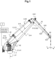
- This support structure 2 comprises articulation means 21 (also called “slewing mechanism”), for example an orientation ring with ball bearing, to define a pivoting movement of the articulated boom 3 along a pivot axis 21' (also called “slewing”).
- articulation means 21 also called “slewing mechanism”
- orientation ring with ball bearing for example an orientation ring with ball bearing
- This 21' pivot axis thus gives a degree of freedom in rotation to the articulated boom 3.
- the support structure 2 and the upstream end 312 of the main boom 31 cooperate by means of upstream articulation means 35 to define an oscillation movement of said main boom 31 along an upstream articulation axis 35' (also called “luffing" or lifting movement), advantageously horizontal and perpendicular to the pivot axis 21'.
- upstream articulation means 35 also called "luffing" or lifting movement
- the main boom 31 is intended to be maneuvered in rotation relative to the support structure 2, around this upstream articulation axis 35' located at its upstream end 312.
- downstream end 313 of the main boom 31 and the upstream end 322 of the terminal boom 32 cooperate by means of downstream articulation means 36 to define a folding movement of said terminal boom 32 along a downstream articulation axis 36' (called “folding" axis), advantageously horizontal and perpendicular to the pivot axis 21'.
- the terminal boom 32 is intended to be maneuvered in rotation relative to the main boom 31, around the downstream articulation axis 36' located at its upstream end 322.
- the upstream 35 and downstream 36 articulation means advantageously consist of articulations, for example in the form of rolling bearings, which are arranged between the assembled ends (for example of the bearing/pin type).
- the upstream 35' and downstream 36' articulation axes extend parallel to each other, advantageously horizontally.
- the downstream end 323 of the terminal boom 32 is controlled in space by the maneuvering means 4 which are controlled by the control means 5.
- upstream ends 421, 431 and downstream ends 422, 432 are advantageously assembled within the crane 1 by means of upstream and downstream articulation means which advantageously consist of articulations, for example in the form of rolling bearings (for example of the bearing/trunnion type).
- said at least one pivot actuator 41 consists, for example, of a motor member integrated into the support structure 2.
- linear actuators 42, 43 advantageously consist of hydraulic cylinders, preferably associated with a hydraulic unit (not shown).
- the linear actuators 42, 43 can also consist of electric cylinders.
- control means 5 are designed to control the maneuvering means 4 so as to stabilize (in space, advantageously along the three axes) the downstream end 323 of the terminal boom 32.
- control means 5 are designed to stabilize the downstream end 323 of the terminal boom 32 in a horizontal plane and/or a vertical position, or even in all directions.
- horizontal plane we advantageously mean a stabilization in the plane defined by the width (x or abscissa axis, horizontal) and the depth (y or ordinate axis).
- vertical position we advantageously mean a height stabilization (z axis or dimension, vertical).
- all directions we advantageously mean stabilization in width (x-axis or abscissa, horizontal), in depth (y-axis or ordinate) and in height (z-axis or dimension, vertical).
- control means 5 comprise an active compensation module 51 (also called “Active 3D Compensation”) which is designed to control the maneuvering means 4, taking into account data coming from a movement acquisition module 7 (also called “MRU” for “Motion Reference Unit”), so as to stabilize the downstream end 323 of the terminal boom 32, advantageously in a horizontal plane and/or a vertical position, or even in all directions.
- active compensation module 51 also called “Active 3D Compensation”
- MRU Motion Reference Unit
- the active compensation module 51 is thus structured to control the maneuvering means 4 so as to compensate for the movements of the crane 1, and in particular of the downstream end 323 of the terminal boom 32, caused by the waves.
- Such an active compensation module 51 thus provides precise positioning of the downstream end 323 of the terminal boom 32, making it possible to maintain this downstream end 323 of the terminal boom 32 in a constant position.
- control means 5 comprise a computer.
- active compensation module 51 comprises a computer program which comprises instructions which, when said computer program is executed by said computer, form the data collection means 511, the processing means 512 and the control means 513, when it is executed on said computer.
- the active compensation module 51 thus advantageously constitutes a computer-controlled system which makes it possible to maintain the position of the downstream end 323 of the terminal boom 32 (compensating for movements caused by waves), using the maneuvering means 4.
- the operator can control the articulated boom crane 1 via the control means 5, during which the movements caused by the waves are compensated by the active compensation module 51.
- the processing means 512 advantageously comprise a mathematical model or algorithm, which determines the control instructions for the maneuvering means 4, which are adapted to stabilize the downstream end 323 of the terminal boom 32 as a function of the data coming from the movement acquisition module 7 (or, in other words, adapted to compensate for the movements caused by the waves).
- the maneuvering means 4 are controlled by the active compensation module 51 according to the invention so as to maneuver the downstream end 323 of the terminal boom 32, advantageously along the three axes, taking into account the information coming from the movement acquisition module 7 so as to stabilize (in space, advantageously along the three axes) this downstream end 323 of the terminal boom 32.
- the movement acquisition module 7 can be chosen from among the movement acquisition modules 7 known to those skilled in the art.
- Such a movement acquisition module 7, advantageously conventional in itself, is designed to record and evaluate the movements of the craft due to the waves and, as a corollary, the movements of the downstream end 323 of the terminal boom 32.
- This movement acquisition module 7 consists, for example, of an inertial unit.
- the articulated boom crane 1 may include this movement acquisition module 7; alternatively, this movement acquisition module 7 may equip the machine.
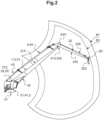
- the articulated arrow 3, illustrated on the Figures 1 to 3 is particularly suitable for equipping an articulated boom crane 1 whose control means 5 include such an active compensation module 51.
- such an articulated boom 3 according to the invention is intrinsically interesting, possibly for equipping an articulated boom crane 1 whose control means 5 are devoid of such an active compensation module 51 or when the compensation mode 51 is inactivated.
- said at least one second linear actuator 43 here has a particular layout in that it is connected here to the support structure 2 and to the terminal arrow 32.
- the folding movement of the terminal boom 32 requires reduced power for the oscillating movement of the main boom 31.
- This approach is interesting because the oscillating movement of the main boom 31 (lifting) consumes most of the energy in compensation mode.
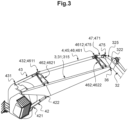
- said at least one second linear actuator 43 is advantageously connected to the terminal boom 32 by means of mechanical transmission means 45 (see in particular the figure 3 ).
- said at least one longitudinal arm 461 advantageously extends opposite and along the main boom 31, in particular its upper front wall 315.
- Said at least two oscillating arms 462 (here in the form of a ladder or H) are assembled, in a rotatable manner (free to rotate), with the longitudinal arm 461 and the main boom 31.
- the swing arms 462 are assembled here with the upper front wall 315 of the main boom 31.
- the mechanical transmission means 45 also comprise a junction member 47, interposed between the downstream end 4612 of said at least one longitudinal arm 461 and the upstream end 322 of the terminal boom 32.
- This junction member 47 extends the terminal arrow 32 on the side of its upstream end 322.
- the mechanical transmission means 45 comprise a connecting rod-crank type assembly, with the intermediate arm 471 forming a connecting rod and the extension section 325 forming a crank.
- said at least one first linear actuator 42 (also called “luffing cylinder”) is arranged between the support structure 2 and the main boom 31.
- Said at least one first linear actuator 42 extends here opposite the lower front wall 314 of the main boom 31.
- said at least one first linear actuator 42 and said at least one second linear actuator 43 are located on either side of the main boom 31, for example respectively facing its lower front wall 314 and its upper front wall 315.
- the articulated boom crane 1 may also comprise a winch drum 8 associated with rotation drive means (not shown, for example at least one motor, advantageously electric or hydraulic) and intended to receive an elongated lifting member 81 (advantageously a cable, for example a metal cable or a synthetic cable).
- rotation drive means not shown, for example at least one motor, advantageously electric or hydraulic
- elongated lifting member 81 a cable, for example a metal cable or a synthetic cable.
- the winch drum 8 is here carried by the terminal boom 32, at its upper face 325 and on the side of its upstream end 322.
- the articulated boom 3 is advantageously equipped with pulleys 82, here distributed along the terminal boom 32, which are sized, distributed and arranged to guide the elongated lifting member 81 between the winch drum 8 and the load to be lifted (not shown).
- the active compensation module 51 is designed to also control the winch drum 8 (in particular its rotation drive means), taking into account data coming from the movement acquisition module 7, so as to control the winding (and unwinding) movement of the winch drum 8.
- the winch drum 8 may be used to smooth the vertical compensation, in order to maintain the vertical position of the free end of the elongated lifting member 81.
- This approach offers the advantage of allowing a second-order, vertical (in height) correction, in combination with the movements of the articulated boom 3.
- the stabilization of the downstream end 323 of the terminal boom 32 (by controlling the maneuvering means 4) is coordinated with the winding movement of the winch drum 8.
- the active compensation module 51 thus advantageously constitutes a computer-controlled system which makes it possible to maintain the downstream end 323 of the terminal boom 32 using the operating means 4, or even to maintain the free end (intended to cooperate with a load) of the elongated lifting member 81 in a determined vertical position.
- the processing means 512 advantageously comprise a mathematical model or algorithm, which determines the control instructions for the maneuvering means 4 which are adapted to stabilize the downstream end 323 of the terminal boom 32 (or also the control instructions for the winch drum 8, in particular its rotation drive means, which are adapted to vertically stabilize the free end of the elongated lifting member 81 in a determined vertical position) as a function of the data coming from the movement acquisition module 7.
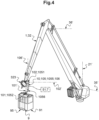
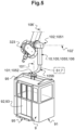
- the articulated boom crane 1 also advantageously includes a platform 9 which is secured to the downstream end 323 of the terminal boom 32 by means of connection means 10.
- platform we advantageously mean a structure intended to receive individuals (generally a cabin) or loads, with a view to their transfer.
- the platform 9 is advantageously suspended from the articulated boom 3 by means of the connection means 10.
- connection means 10 ensure active stabilization of the platform 9 during movements of the articulated boom 3.
- This active stabilization advantageously occurs at least along one axis of rotation in pitch (advantageously horizontal) and along one axis of rotation in yaw (advantageously vertical).
- the platform 9 advantageously defines a reception plane 91 which is advantageously intended to be horizontally stable, advantageously in pitch and yaw.
- the yaw rotation axis 101' and the pitch rotation axis 102' advantageously extend in the same plane; the yaw rotation axis 101' and the pitch rotation axis 102' preferably converge at 90°.
- the actuators 101, 102 advantageously consist of rotary actuators, for example motors, preferably electric motors.
- the active compensation module 51 is advantageously designed to also control the actuators 101, 102 equipping the connection means 10, taking into account data coming from a movement acquisition module (advantageously equipping the platform 9), so as to actively stabilize the platform 9, advantageously in yaw and pitch.
- the active compensation module 51 is thus structured to control the actuators 101, 102 of the connection means 10 so as to prevent the swings generated by the movements of the articulated boom 3, and in particular of the downstream end 323 of the terminal boom 32.
- the active compensation module 51 thus provides active stabilization of the platform 9 with respect to the movements of the downstream end 323 of the terminal boom 32.
- the active compensation module 51 thus advantageously constitutes a computer-controlled system which makes it possible to stabilize the platform 9 (preventing or compensating for the swings caused by the movement of the articulated boom 3), using the actuators 101, 102 of the connection means 10.
- the actuators 101, 102 of the connection means 10 are controlled by the active compensation module 51 according to the invention so as to stabilize the platform 9, taking into account the information coming from the dedicated movement acquisition module.
- connection means 10 comprise a connecting member 105 integrating the aforementioned actuators 101, 102.
- the assembly of the first end 1051 with the downstream end 323 of the terminal boom 32, on the one hand, and of the second end 1052 with the platform 9, is for example carried out by means of a bearing, for example a smooth bearing or a rolling bearing, equipped with the actuators 101, 102.
- a bearing for example a smooth bearing or a rolling bearing, equipped with the actuators 101, 102.
- the connecting member 105 is advantageously secured laterally to the downstream end 323 of the terminal arrow 32.
- the point of intersection between the yaw rotation axis 101' and the pitch rotation axis 102' is advantageously located at the downstream end 323 of the terminal boom 32.
- This embodiment has the advantage of keeping the position of the yaw rotation axis 101' and the pitch rotation axis 102' at the downstream end 323 of the terminal boom 32.
- connection means 10 comprise damping means 106, advantageously passive, conferring a degree of freedom in translation of the platform 9 relative to the downstream end 323 of the terminal boom 32.
- the damping means 106 allow clearance between the ends 1051, 1052 of the connecting member 105.
- the damping means 106 thus define a translation axis 106' which is parallel to the yaw rotation axis 101'.
- the shock absorbing means 106 are advantageously placed between the upper section 1055 and the lower section 1056.
- the damping means 106 consist, for example, of a spring and a visco-hydraulic suspension, to prevent jerky movements of the platform 9.
- the platform 9 consists for example of a cabin adapted to receive at least one individual.
- the reception plan 91 corresponds advantageously to the floor of this cabin.
- the platform 9 advantageously comprises at least one passive shock-absorbing member 95 (for example elastomer blocks), adapted to absorb contact with the environment.
- passive shock-absorbing member 95 for example elastomer blocks
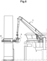
- the damping member 95 is for example adapted to cooperate with a receiving surface R consisting of a platform carried by the mast of a wind turbine, as illustrated in the figure 6 .
- said at least one shock-absorbing member 95 is advantageously located at the level of the receiving plane 91, for example on at least one side and/or below (for example at the level of an access door 93).
- the platform 9 is advantageously equipped with manual control means (not shown), for the manual control of the actuators 101, 102 of the connection means 10.
- connection means 10 cooperate by means of removable connection means, integrating electrical and mechanical connection means (in particular for the power supply of the actuators 101, 102 of the connection means 10).
- the removable connecting means are advantageously provided between the downstream end 323 of the terminal arrow 32 and the first end 1051 (upper) of the connecting member 105.
- the connecting member 105 is thus carried by the platform 9, after separation from the downstream end 323 of the terminal boom 32.
- the platform 9, with its connection means 10, could possibly be adapted to an articulated boom crane other than that according to the invention.
Landscapes
- Engineering & Computer Science (AREA)
- Mechanical Engineering (AREA)
- Structural Engineering (AREA)
- Life Sciences & Earth Sciences (AREA)
- Geology (AREA)
- Automation & Control Theory (AREA)
- Jib Cranes (AREA)
Applications Claiming Priority (3)
| Application Number | Priority Date | Filing Date | Title |
|---|---|---|---|
| FR2012580A FR3117099B1 (fr) | 2020-12-03 | 2020-12-03 | Grue à flèche articulée, pour application offshore |
| FR2108433A FR3117100B1 (fr) | 2020-12-03 | 2021-08-03 | Grue à flèche articulée, pour application offshore |
| EP21211889.7A EP4008679B1 (de) | 2020-12-03 | 2021-12-02 | Gelenkauslegerkran für den offshore-einsatz |
Related Parent Applications (1)
| Application Number | Title | Priority Date | Filing Date |
|---|---|---|---|
| EP21211889.7A Division EP4008679B1 (de) | 2020-12-03 | 2021-12-02 | Gelenkauslegerkran für den offshore-einsatz |
Publications (2)
| Publication Number | Publication Date |
|---|---|
| EP4464648A2 true EP4464648A2 (de) | 2024-11-20 |
| EP4464648A3 EP4464648A3 (de) | 2025-01-15 |
Family
ID=78725396
Family Applications (2)
| Application Number | Title | Priority Date | Filing Date |
|---|---|---|---|
| EP21211889.7A Active EP4008679B1 (de) | 2020-12-03 | 2021-12-02 | Gelenkauslegerkran für den offshore-einsatz |
| EP24204077.2A Pending EP4464648A3 (de) | 2020-12-03 | 2021-12-02 | Kran mit gelenkigem ausleger für offshore-anwendung |
Family Applications Before (1)
| Application Number | Title | Priority Date | Filing Date |
|---|---|---|---|
| EP21211889.7A Active EP4008679B1 (de) | 2020-12-03 | 2021-12-02 | Gelenkauslegerkran für den offshore-einsatz |
Country Status (5)
| Country | Link |
|---|---|
| US (1) | US11858783B2 (de) |
| EP (2) | EP4008679B1 (de) |
| CN (1) | CN114590721A (de) |
| BR (1) | BR102021024450A2 (de) |
| DK (1) | DK4008679T3 (de) |
Families Citing this family (1)
| Publication number | Priority date | Publication date | Assignee | Title |
|---|---|---|---|---|
| CN116477474A (zh) * | 2022-08-08 | 2023-07-25 | 中国船舶重工集团公司第七一三研究所 | 一种船用起重机的自动防摇控制方法 |
Citations (3)
| Publication number | Priority date | Publication date | Assignee | Title |
|---|---|---|---|---|
| WO2012002809A1 (en) | 2010-06-28 | 2012-01-05 | Ihc Holland Ie B.V. | Lifting device and method for positioning of an unwieldy object |
| WO2018199743A2 (en) | 2017-04-24 | 2018-11-01 | Itrec B.V. | A motion compensating crane for use on an offshore vessel |
| WO2020085902A1 (en) | 2018-10-23 | 2020-04-30 | Itrec B.V. | Installation of a wind turbine blade on a hub of a wind turbine |
Family Cites Families (14)
| Publication number | Priority date | Publication date | Assignee | Title |
|---|---|---|---|---|
| US3961713A (en) * | 1974-06-28 | 1976-06-08 | Houston Systems, Inc. | Single line davit |
| GB2163402B (en) * | 1984-08-22 | 1987-12-31 | British Aerospace | Open sea transfer of articles |
| EP2194017B1 (de) | 2008-12-03 | 2011-10-12 | Engineering-Support AS | Offshore-Kran |
| EP2370925B1 (de) * | 2008-12-15 | 2021-03-03 | Oceaneering International, Inc. | Ladungsmanipulator für eine bohrinsel |
| NO336245B1 (no) * | 2010-09-21 | 2015-06-29 | Rolls Royce Marine As | Hivkompensert kran |
| WO2014200354A1 (en) * | 2012-06-06 | 2014-12-18 | Seaonicas As | Hybrid crane |
| MX354333B (es) | 2012-07-16 | 2018-02-26 | Itrec Bv | Grúa marina de pluma articulada. |
| EP3388384B1 (de) | 2012-08-06 | 2024-07-10 | Itrec B.V. | Schwimmkran |
| CN204510303U (zh) | 2015-03-16 | 2015-07-29 | 江西蓝翔重工有限公司 | 多臂组合变幅式挖掘钻装一体机 |
| NL2015113B1 (en) * | 2015-07-07 | 2017-02-01 | Coöperatieve Ver Offshore Coop U A | A method for transporting a person from a first position relative to a watercraft to a second position relative to the watercraft, a device for transporting the person, and a system and a watercraft comprising the device. |
| NL2016444B1 (en) * | 2016-03-04 | 2017-09-19 | U-Sea Beheer B V | Disturbance compensating telescopic knuckle boom crane, ship provided therewith and method therefor |
| EP3318530B1 (de) * | 2016-11-03 | 2020-04-01 | National Oilwell Varco Norway AS | Verfahren zur verbesserung eines gelenkauslegerkrans und kran mit hubkompensation |
| NL2020664B1 (en) * | 2018-03-26 | 2019-10-07 | Barge Master Ip B V | Offshore crane |
| CN113135506B (zh) | 2021-04-30 | 2023-05-26 | 三一海洋重工有限公司 | 一种液压平衡起重机 |
-
2021
- 2021-12-02 EP EP21211889.7A patent/EP4008679B1/de active Active
- 2021-12-02 EP EP24204077.2A patent/EP4464648A3/de active Pending
- 2021-12-02 DK DK21211889.7T patent/DK4008679T3/da active
- 2021-12-03 BR BR102021024450-0A patent/BR102021024450A2/pt unknown
- 2021-12-03 CN CN202111467073.8A patent/CN114590721A/zh active Pending
- 2021-12-03 US US17/541,713 patent/US11858783B2/en active Active
Patent Citations (3)
| Publication number | Priority date | Publication date | Assignee | Title |
|---|---|---|---|---|
| WO2012002809A1 (en) | 2010-06-28 | 2012-01-05 | Ihc Holland Ie B.V. | Lifting device and method for positioning of an unwieldy object |
| WO2018199743A2 (en) | 2017-04-24 | 2018-11-01 | Itrec B.V. | A motion compensating crane for use on an offshore vessel |
| WO2020085902A1 (en) | 2018-10-23 | 2020-04-30 | Itrec B.V. | Installation of a wind turbine blade on a hub of a wind turbine |
Also Published As
| Publication number | Publication date |
|---|---|
| EP4008679B1 (de) | 2024-10-23 |
| EP4464648A3 (de) | 2025-01-15 |
| DK4008679T3 (da) | 2024-11-25 |
| BR102021024450A2 (pt) | 2022-06-14 |
| US20220177279A1 (en) | 2022-06-09 |
| CN114590721A (zh) | 2022-06-07 |
| EP4008679A1 (de) | 2022-06-08 |
| US11858783B2 (en) | 2024-01-02 |
Similar Documents
| Publication | Publication Date | Title |
|---|---|---|
| EP0040159B1 (de) | Manipulator | |
| CA2879172C (fr) | Essieu et vehicule comprenant au moins un tel essieu | |
| EP2374635B1 (de) | Achssystem, Achsmodul, das mindestens ein solches Achssytem umfasst und Fahrzeug, das mindestens ein solches Modul umfasst | |
| EP4144918A1 (de) | System zum vorübergehenden aufrechterhalten eines gründungspfahls zur aufnahme des mastes einer offshore-windkraftanlage während der rammarbeiten | |
| EP4049936B1 (de) | System mit einem beweglichen schlitten und verfahren zur anwendung eines solchen systems mit beweglichem schlitten | |
| EP4008679B1 (de) | Gelenkauslegerkran für den offshore-einsatz | |
| EP1879827B1 (de) | Schlingenvorrichtung für ein teil mit kraftausgleich und diese umfassendes hubsystem | |
| FR3050675A1 (fr) | Manipulateur de pieces | |
| FR2956107A1 (fr) | Vehicule elevateur pour le positionnement d'une charge en hauteur | |
| FR3117099A1 (fr) | Grue à flèche articulée, pour application offshore | |
| FR2877659A1 (fr) | Dispositif elevateur, notamment pour permettre l'acces du personnel de maintenance aux differentes parties d'un avion | |
| JP7345391B2 (ja) | 洋上作業中に人々および/または貨物を移送するためのシステム | |
| FR2550984A1 (fr) | Installation flexible de couples robot-porteurs | |
| EP2761061B1 (de) | Kompaktes dienstmodul und seine verwendung in einer anlage zur herstellung von aluminium durch elektrolyse | |
| EP1061034A1 (de) | Selbstangetriebener Wagen mit teleskopischem Arm und Hebungarm | |
| EP1953112A1 (de) | Hubgerät | |
| KR102171114B1 (ko) | 차량용 중량물의 상하차용 장치 | |
| FR3128811A1 (fr) | Système de démantèlement pour une installation nucléaire | |
| FR3015915B1 (fr) | Chassis de vehicule omnidirectionnel comportant des corps de chassis deplacables l'un par rapport a l'autre | |
| EP4653374A1 (de) | Offshore-anwendungsfahrzeug mit einer brücke mit einem knickauslegerkran | |
| FR2705630A1 (fr) | Engin de transport de charges d'encombrement important équipé d'une plate-forme orientable support de la charge. | |
| EP3842374B1 (de) | Gelenkauslegerkran für den offshore-einsatz | |
| EP4361352B1 (de) | Autonome handhabungsmaschine | |
| FR2552050A1 (fr) | Ensemble propulseur a helice de bateau | |
| BE1032917A1 (fr) | Grue marine télescopique à bras articulé pliant équipée d’une plateforme de compensation de mouvement à fluide magnétorhéologique et son procédé de fonctionnement |
Legal Events
| Date | Code | Title | Description |
|---|---|---|---|
| PUAI | Public reference made under article 153(3) epc to a published international application that has entered the european phase |
Free format text: ORIGINAL CODE: 0009012 |
|
| STAA | Information on the status of an ep patent application or granted ep patent |
Free format text: STATUS: THE APPLICATION HAS BEEN PUBLISHED |
|
| AC | Divisional application: reference to earlier application |
Ref document number: 4008679 Country of ref document: EP Kind code of ref document: P |
|
| AK | Designated contracting states |
Kind code of ref document: A2 Designated state(s): AL AT BE BG CH CY CZ DE DK EE ES FI FR GB GR HR HU IE IS IT LI LT LU LV MC MK MT NL NO PL PT RO RS SE SI SK SM TR |
|
| REG | Reference to a national code |
Ref country code: DE Ref legal event code: R079 Free format text: PREVIOUS MAIN CLASS: B66F0011040000 Ipc: B66C0023530000 |
|
| PUAL | Search report despatched |
Free format text: ORIGINAL CODE: 0009013 |
|
| TPAC | Observations filed by third parties |
Free format text: ORIGINAL CODE: EPIDOSNTIPA |
|
| AK | Designated contracting states |
Kind code of ref document: A3 Designated state(s): AL AT BE BG CH CY CZ DE DK EE ES FI FR GB GR HR HU IE IS IT LI LT LU LV MC MK MT NL NO PL PT RO RS SE SI SK SM TR |
|
| RIC1 | Information provided on ipc code assigned before grant |
Ipc: B66F 11/04 20060101ALI20241211BHEP Ipc: B66C 13/02 20060101ALI20241211BHEP Ipc: B63B 27/16 20060101ALI20241211BHEP Ipc: B66C 23/68 20060101ALI20241211BHEP Ipc: B66C 23/64 20060101ALI20241211BHEP Ipc: B66C 23/18 20060101ALI20241211BHEP Ipc: B66C 23/53 20060101AFI20241211BHEP |
|
| P01 | Opt-out of the competence of the unified patent court (upc) registered |
Free format text: CASE NUMBER: APP_19292/2025 Effective date: 20250423 |
|
| STAA | Information on the status of an ep patent application or granted ep patent |
Free format text: STATUS: REQUEST FOR EXAMINATION WAS MADE |
|
| 17P | Request for examination filed |
Effective date: 20250711 |