EP4464952A1 - Climatiseur - Google Patents
Climatiseur Download PDFInfo
- Publication number
- EP4464952A1 EP4464952A1 EP22920157.9A EP22920157A EP4464952A1 EP 4464952 A1 EP4464952 A1 EP 4464952A1 EP 22920157 A EP22920157 A EP 22920157A EP 4464952 A1 EP4464952 A1 EP 4464952A1
- Authority
- EP
- European Patent Office
- Prior art keywords
- load
- heat
- refrigerant
- air
- heat exchanger
- Prior art date
- Legal status (The legal status is an assumption and is not a legal conclusion. Google has not performed a legal analysis and makes no representation as to the accuracy of the status listed.)
- Withdrawn
Links
Images




Classifications
-
- F—MECHANICAL ENGINEERING; LIGHTING; HEATING; WEAPONS; BLASTING
- F25—REFRIGERATION OR COOLING; COMBINED HEATING AND REFRIGERATION SYSTEMS; HEAT PUMP SYSTEMS; MANUFACTURE OR STORAGE OF ICE; LIQUEFACTION SOLIDIFICATION OF GASES
- F25B—REFRIGERATION MACHINES, PLANTS OR SYSTEMS; COMBINED HEATING AND REFRIGERATION SYSTEMS; HEAT PUMP SYSTEMS
- F25B13/00—Compression machines, plants or systems, with reversible cycle
-
- F—MECHANICAL ENGINEERING; LIGHTING; HEATING; WEAPONS; BLASTING
- F24—HEATING; RANGES; VENTILATING
- F24F—AIR-CONDITIONING; AIR-HUMIDIFICATION; VENTILATION; USE OF AIR CURRENTS FOR SCREENING
- F24F11/00—Control or safety arrangements
- F24F11/30—Control or safety arrangements for purposes related to the operation of the system, e.g. for safety or monitoring
- F24F11/32—Responding to malfunctions or emergencies
- F24F11/36—Responding to malfunctions or emergencies to leakage of heat-exchange fluid
-
- F—MECHANICAL ENGINEERING; LIGHTING; HEATING; WEAPONS; BLASTING
- F24—HEATING; RANGES; VENTILATING
- F24F—AIR-CONDITIONING; AIR-HUMIDIFICATION; VENTILATION; USE OF AIR CURRENTS FOR SCREENING
- F24F11/00—Control or safety arrangements
- F24F11/70—Control systems characterised by their outputs; Constructional details thereof
- F24F11/80—Control systems characterised by their outputs; Constructional details thereof for controlling the temperature of the supplied air
- F24F11/86—Control systems characterised by their outputs; Constructional details thereof for controlling the temperature of the supplied air by controlling compressors within refrigeration or heat pump circuits
-
- F—MECHANICAL ENGINEERING; LIGHTING; HEATING; WEAPONS; BLASTING
- F25—REFRIGERATION OR COOLING; COMBINED HEATING AND REFRIGERATION SYSTEMS; HEAT PUMP SYSTEMS; MANUFACTURE OR STORAGE OF ICE; LIQUEFACTION SOLIDIFICATION OF GASES
- F25B—REFRIGERATION MACHINES, PLANTS OR SYSTEMS; COMBINED HEATING AND REFRIGERATION SYSTEMS; HEAT PUMP SYSTEMS
- F25B41/00—Fluid-circulation arrangements
- F25B41/20—Disposition of valves, e.g. of on-off valves or flow control valves
- F25B41/22—Disposition of valves, e.g. of on-off valves or flow control valves between evaporator and compressor
-
- F—MECHANICAL ENGINEERING; LIGHTING; HEATING; WEAPONS; BLASTING
- F25—REFRIGERATION OR COOLING; COMBINED HEATING AND REFRIGERATION SYSTEMS; HEAT PUMP SYSTEMS; MANUFACTURE OR STORAGE OF ICE; LIQUEFACTION SOLIDIFICATION OF GASES
- F25B—REFRIGERATION MACHINES, PLANTS OR SYSTEMS; COMBINED HEATING AND REFRIGERATION SYSTEMS; HEAT PUMP SYSTEMS
- F25B49/00—Arrangement or mounting of control or safety devices
- F25B49/02—Arrangement or mounting of control or safety devices for compression type machines, plants or systems
-
- F—MECHANICAL ENGINEERING; LIGHTING; HEATING; WEAPONS; BLASTING
- F24—HEATING; RANGES; VENTILATING
- F24F—AIR-CONDITIONING; AIR-HUMIDIFICATION; VENTILATION; USE OF AIR CURRENTS FOR SCREENING
- F24F3/00—Air-conditioning systems in which conditioned primary air is supplied from one or more central stations to distributing units in the rooms or spaces where it may receive secondary treatment; Apparatus specially designed for such systems
- F24F3/06—Air-conditioning systems in which conditioned primary air is supplied from one or more central stations to distributing units in the rooms or spaces where it may receive secondary treatment; Apparatus specially designed for such systems characterised by the arrangements for the supply of heat-exchange fluid for the subsequent treatment of primary air in the room units
-
- F—MECHANICAL ENGINEERING; LIGHTING; HEATING; WEAPONS; BLASTING
- F25—REFRIGERATION OR COOLING; COMBINED HEATING AND REFRIGERATION SYSTEMS; HEAT PUMP SYSTEMS; MANUFACTURE OR STORAGE OF ICE; LIQUEFACTION SOLIDIFICATION OF GASES
- F25B—REFRIGERATION MACHINES, PLANTS OR SYSTEMS; COMBINED HEATING AND REFRIGERATION SYSTEMS; HEAT PUMP SYSTEMS
- F25B2313/00—Compression machines, plants or systems with reversible cycle not otherwise provided for
- F25B2313/023—Compression machines, plants or systems with reversible cycle not otherwise provided for using multiple indoor units
- F25B2313/0233—Compression machines, plants or systems with reversible cycle not otherwise provided for using multiple indoor units in parallel arrangements
-
- F—MECHANICAL ENGINEERING; LIGHTING; HEATING; WEAPONS; BLASTING
- F25—REFRIGERATION OR COOLING; COMBINED HEATING AND REFRIGERATION SYSTEMS; HEAT PUMP SYSTEMS; MANUFACTURE OR STORAGE OF ICE; LIQUEFACTION SOLIDIFICATION OF GASES
- F25B—REFRIGERATION MACHINES, PLANTS OR SYSTEMS; COMBINED HEATING AND REFRIGERATION SYSTEMS; HEAT PUMP SYSTEMS
- F25B2313/00—Compression machines, plants or systems with reversible cycle not otherwise provided for
- F25B2313/029—Control issues
- F25B2313/0294—Control issues related to the outdoor fan, e.g. controlling speed
-
- F—MECHANICAL ENGINEERING; LIGHTING; HEATING; WEAPONS; BLASTING
- F25—REFRIGERATION OR COOLING; COMBINED HEATING AND REFRIGERATION SYSTEMS; HEAT PUMP SYSTEMS; MANUFACTURE OR STORAGE OF ICE; LIQUEFACTION SOLIDIFICATION OF GASES
- F25B—REFRIGERATION MACHINES, PLANTS OR SYSTEMS; COMBINED HEATING AND REFRIGERATION SYSTEMS; HEAT PUMP SYSTEMS
- F25B2500/00—Problems to be solved
- F25B2500/22—Preventing, detecting or repairing leaks of refrigeration fluids
- F25B2500/222—Detecting refrigerant leaks
-
- F—MECHANICAL ENGINEERING; LIGHTING; HEATING; WEAPONS; BLASTING
- F25—REFRIGERATION OR COOLING; COMBINED HEATING AND REFRIGERATION SYSTEMS; HEAT PUMP SYSTEMS; MANUFACTURE OR STORAGE OF ICE; LIQUEFACTION SOLIDIFICATION OF GASES
- F25B—REFRIGERATION MACHINES, PLANTS OR SYSTEMS; COMBINED HEATING AND REFRIGERATION SYSTEMS; HEAT PUMP SYSTEMS
- F25B2600/00—Control issues
- F25B2600/02—Compressor control
- F25B2600/026—Compressor control by controlling unloaders
- F25B2600/0261—Compressor control by controlling unloaders external to the compressor
Definitions
- the present disclosure relates to an air-conditioning apparatus including solenoid valves each of which shuts off the flow of refrigerant when a refrigerant leak occurs.
- Patent Literature discloses an air-conditioning apparatus in which such solenoid valves as described above are provided at one of two pipes connecting a heat source apparatus and a plurality of heat load apparatuses, and expansion valves are provided at the other pipe.
- Patent Literature 1 Japanese Patent No. 5517789
- the present disclosure is applied to solve the above problem, and relates to an air-conditioning apparatus in which a plurality of heat load apparatuses are connected in parallel with a heat source apparatus, and when a refrigerant leak occurs at one of the heat load apparatuses, the amount of the refrigerant leak is reduced.
- An air-conditioning apparatus includes: a first heat load apparatus including a first load-side heat exchanger and a first load-side expansion valve, the first load-side heat exchanger being configured to cause heat exchange to be performed between refrigerant and air in a target space, the first load-side expansion valve being configured to expand the refrigerant that is to flow into the first load-side heat exchanger or the refrigerant that has flowed out from the first load-side heat exchanger; a second heat load apparatus includes a second load-side heat exchanger and a second load-side expansion valve, the second load-side heat exchanger being configured to cause heat exchange to be performed between the refrigerant and air in a target space, the second load-side expansion valve being configured to expand the refrigerant that is to flow into the second load-side heat exchanger or the refrigerant that has flowed out from the second load-side heat exchanger; a heat source apparatus including a compressor configured to compress the refrigerant, the heat source apparatus being configured
- the controller is configured to close the first load-side expansion valve and the solenoid valve and increase an opening degree of the second load-side expansion valve from a present opening degree thereof, when a refrigerant leak in the first heat load apparatus is detected and no refrigerant leak in the second heat load apparatus is detected.
- a load-side expansion valve and a solenoid valve that are associated with a heat load apparatus in which a refrigerant leak occurs are closed, and opening degrees of expansion valves that are associated with heat load apparatuses in which a refrigerant leak does not occur are increased from the present opening degrees.
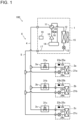
- Fig. 1 is a circuit diagram of an air-conditioning apparatus 100 according to Embodiment 1.
- the air-conditioning apparatus 100 according to Embodiment 1 air-conditions a plurality of target spaces such as indoor spaces in, for example, a building.
- the air-conditioning apparatus 100 includes a heat source apparatus 1, a plurality of heat load apparatuses 2a to 2c, and a plurality of shut-off devices 3a to 3c.
- the heat load apparatus 2a corresponds to the "first heat load apparatus" of the present disclosure
- the heat load apparatus 2b corresponds to the "second heat load apparatus" of the present disclosure.
- the number of heat load apparatuses may be two or four more.
- the heat source apparatus 1 is, for example, an outdoor unit installed outside the target spaces.
- the heat load apparatuses 2a to 2c of the air-conditioning apparatus 100 supplies heating energy or cooling energy to the target spaces, using refrigerant supplied from the heat source apparatus 1.
- the heat load apparatuses 2a to 2c are installed, for example, in the target spaces and are indoor units that perform cooling or heating.
- the heat load apparatuses 2a to 2c are connected to the heat source apparatus 1 by refrigerant pipes 4 and 5 through which the refrigerant flows.
- the refrigerant pipes 4 and 5 branch to extend to the heat load apparatuses 2a to 2c.
- the heat load apparatuses 2a to 2c and the heat source apparatus 1 are connected in parallel.
- the heat source apparatus 1 includes a compressor 10, a flow switching valve 11, a refrigerant heat exchanger 12, a heat-source-side expansion valve 13, an accumulator 14, a fan 15, a bypass valve 16, a heat-source-side refrigerant pipe 17, a bypass pipe 18, and a heat-source-side controller 19.
- the compressor 10 sucks low-temperature and low-pressure gas refrigerant, compresses the low-temperature and low-pressure gas refrigerant to change it into high-temperature and high-pressure gas refrigerant, and discharges the high-temperature and high-pressure gas refrigerant.
- the compressor 10 is, for example, an inverter compressor 10 whose capacity can be controlled.
- the flow switching valve 11 is, for example, a four-way valve.
- the flow switching valve 11 switches the flow passage for refrigerant discharged from the compressor 10 between plural flow passages, depending on operations of the heat load apparatuses 2a to 2c. In a cooling operation, the flow switching valve 11 switches the flow passage to a flow passage indicated by arrows as indicated in Fig. 2 ; and in a heating operation, the flow switching valve 11 switches the flow passage to a flow passage indicated by arrows as indicated in Fig. 3 . This will be described later in detail. It should be noted that the flow switching valve 11 may be a combination of three-way valves or two-way valves.
- the refrigerant heat exchanger 12 is, for example, a fin tube heat exchanger.
- the refrigerant heat exchanger 12 causes heat exchange to be performed between the refrigerant and air supplied by the fan 15.
- the refrigerant heat exchanger 12 operates as a condenser to condense and liquefy the refrigerant.
- the refrigerant heat exchanger 12 operates as an evaporator to evaporate and gasify the refrigerant.
- the heat-source-side expansion valve 13 is an electronic expansion valve whose opening degree can be variably controlled.
- the heat-source-side expansion valve 13 is connected in series to the refrigerant heat exchanger 12, and decompresses and expands refrigerant that has flowed out from the refrigerant heat exchanger 12 or refrigerant that is to flow into the refrigerant heat exchanger 12.
- the accumulator 14 is provided on a suction side of the compressor 10, and has a function of separating liquid refrigerant and gas refrigerant from each other and a function of storing surplus refrigerant.
- the fan 15 is, for example, a propeller fan.
- the fan 15 supplies air around the heat source apparatus 1 to the refrigerant heat exchanger 12.
- the rotation speed of the fan 15 is controlled by the heat-source-side controller 19, whereby a condensing performance or an evaporating performance of the refrigerant heat exchanger 12 is controlled.
- the bypass valve 16 is provided at the bypass pipe 18.
- the bypass valve 16 is controlled in opening degree by the heat-source-side controller 19, thereby adjusting the flow rate of refrigerant that flows through the bypass pipe 18.
- the heat-source-side refrigerant pipe 17 is one of pipes in the air-conditioning apparatus 100 that is located in a housing (not illustrated) of the heat source apparatus 1.
- the heat-source-side refrigerant pipe 17 connects the heat-source-side expansion valve 13, the refrigerant heat exchanger 12, the accumulator 14, the compressor 10, and the flow switching valve 11 in this order.
- One of ends of the heat-source-side refrigerant pipe 17 that is close to the flow switching valve 11 is connected to the refrigerant pipe 4, and the other end of the heat-source-side refrigerant pipe 17 that is close to the heat-source-side expansion valve 13 is connected to the refrigerant pipe 5.
- the bypass pipe 18 is a pipe that connects a high pressure side and a low pressure side of the compressor 10.
- bypass pipe 18 connects the heat-source-side refrigerant pipe 17 connected to the suction side of the compressor 10 and the heat-source-side refrigerant pipe 17 connected to an inlet side to the accumulator 14, that is, the discharge side of the compressor 10.
- the heat-source-side controller 19 controls operations of the compressor 10, the flow switching valve 11, the heat-source-side expansion valve 13, the fan 15, and the bypass valve 16, which are connected to the heat-source-side controller 19 by wire or wirelessly.
- the heat-source-side controller 19 is a processing device, dedicated hardware such as ASIC or FPGA, or a combination of the processing device or the dedicated hardware.
- the above processing device includes a memory configured to store data and a program that are necessary for control and a CPU that runs the program.
- the heat-source-side controller 19 controls the drive frequency of the compressor 10, a flow passage in the flow switching valve 11, the opening degrees of the heat-source-side expansion valve 13 and the bypass valve 16, and the operation speed of the fan 15 on the basis of the results of detection by sensors.
- the sensors are, for example, a pressure sensor (not illustrated) that is mounted in the heat source apparatus 1 to detect a refrigerant pressure and a temperature sensor (not illustrated) that detects a refrigerant temperature or an outside air temperature.
- the heat-source-side controller 19 can perform data communication with load-side controllers 25a to 25c (to be described later) of the heat load apparatuses 2a to 2c that are connected to the heat-source-side controller 19 by wire or wirelessly. Furthermore, the heat-source-side controller 19 controls, when a refrigerant leak occurs, solenoid valves 31a to 31c (to be descried later) of the shut-off devices 3a to 3c that are connected to the heat-source-side controller 19 by wire or wirelessly.
- the heat-source-side controller 19 indirectly controls load-side expansion valves 22a to 22c (to be described later) of the heat load apparatuses 2a to 2c via the load-side controllers 25a of the heat load apparatuses 2a to 2c. It will be described later how the above components are controlled when a refrigerant leak occurs.
- the heat load apparatuses 2a to 2c supply the cooling load or heating load of the target spaces with heat generated by the heat source apparatus 1.
- the heat load apparatus 2a includes a load-side heat exchanger 21a, the load-side expansion valve 22a, a refrigerant leak detecting sensor 23a, a load-side refrigerant pipe 24a, and the load-side controller 25a.
- the load-side heat exchanger 21a is, for example, a fin tube heat exchanger.
- the load-side heat exchanger 21a causes heat exchange to be performed between air in the target space and the refrigerant.
- the load-side heat exchanger 21a operates as a condenser in the heating operation to condense and liquefy the refrigerant, and operates as an evaporator in the cooling operation to evaporate and gasify the refrigerant.
- the load-side expansion valve 22a is an electronic expansion valve whose opening degree can be variably controlled.
- the load-side expansion valve 22a is connected in series to the load-side heat exchanger 21a, and decompresses and expands refrigerant that has flowed out from the load-side heat exchanger 21a or refrigerant that is to flow into the load-side heat exchanger 21a.
- the refrigerant leak detecting sensor 23a is provided in a housing (not illustrated) of the heat load apparatus 2a to detect a leak of refrigerant from the load-side heat exchanger 21a, the load-side expansion valve 22a, or the load-side refrigerant pipe 24a.
- the refrigerant leak is detected using any of existing various methods of detecting a refrigerant leak, for example, based on the concentration of refrigerant gas in the housing, or by measuring the pressure or temperature of refrigerant that flows through the load-side refrigerant pipe 24a.
- the refrigerant leak detecting sensor 23a When detecting occurrence of a refrigerant leak from the heat load apparatus 2a, the refrigerant leak detecting sensor 23a transmits a detection signal indicating the occurrence of the refrigerant leak from the heat load apparatus 2a to the load-side controller 25a that is connected to the refrigerant leak detecting sensor 23a by wire or wirelessly.
- the load-side refrigerant pipe 24a is one of the pipes in the air-conditioning apparatus 100 that is provided in the housing (not illustrated) of the heat load apparatus 2a.
- the load-side refrigerant pipe 24a connects the load-side heat exchanger 21a and the load-side expansion valve 22a.
- One of ends of the load-side refrigerant pipe 24a that is close to the load-side heat exchanger 21a is connected to the refrigerant pipe 4, and the other end of the load-side refrigerant pipe 24a that is close to the load-side expansion valve 22a is connected to the refrigerant pipe 5.
- the load-side controller 25a controls the operation of the load-side expansion valve 22a connected to the load-side controller 25a by wire or wirelessly.
- the load-side controller 25a is a processing device, dedicated hardware such as ASIC or FPGA, or a combination of the processing device and the dedicated hardware.
- the above processing device includes a memory configured to store data and a program that are necessary for control and a CPU that runs the program.
- the load-side controller 25a controls the opening degree of the load-side expansion valve 22a on the basis of the results of detection by a temperature sensor (not illustrated) configured to detect the temperature of the target space and temperature sensors (not illustrated) configured to detect respective temperatures of refrigerant at an outlet and an inlet of the heat load apparatus 2a.
- the temperature sensors are each, for example, a thermistor. It should be noted that the load-side controller 25a controls the opening degree of the load-side expansion valve 22a on the basis of, for example, the difference between the temperature in the target space and a target temperature.
- the load-side controller 25a transmits a leak occurrence signal to the heat-source-side controller 19.
- the load-side controller 25a closes the load-side expansion valve 22a substantially at the same time as it transmits the leak occurrence signal.
- the leak occurrence signal includes information indicating in which of the heat load apparatuses the refrigerant leak occurs.
- the refrigerant leak detecting sensor 23a may have only a function of transmitting the result of measurement of the concentration of refrigerant gas in the housing or the pressure or temperature of refrigerant that flows through the load-side refrigerant pipe 24a to the load-side controller 25a. In this case, the load-side controller 25a determines whether a refrigerant leak occurs or not based on the result of measurement by the refrigerant leak detecting sensor 23a.
- the heat load apparatuses 2b and 2c each have the same configuration as the heat load apparatus 2a.
- the heat load apparatus 2b includes a load-side heat exchanger 21b, the load-side expansion valve 22b, a refrigerant leak detecting sensor 23b, a load-side refrigerant pipe 24b, and the load-side controller 25b.
- the heat load apparatus 2c includes a load-side heat exchanger 21c, the load-side expansion valve 22c, a refrigerant leak detecting sensor 23c, a load-side refrigerant pipe 24c, and the load-side controller 25c.
- Components included in the heat load apparatuses 2b and 2c also have the same configurations as those in the heat load apparatus 2a, and their descriptions will thus be omitted.
- the load-side heat exchanger 21a corresponds to the "first load-side heat exchanger” of the present disclosure
- the load-side heat exchanger 21b corresponds to the "second load-side heat exchanger” of the present disclosure.
- the load-side expansion valve 22a corresponds to the "first load-side expansion valve” of the present disclosure
- the load-side expansion valve 22b corresponds to the "second load-side expansion valve” of the present disclosure.
- the heat-source-side expansion valve 13, the refrigerant heat exchanger 12, the accumulator 14, the compressor 10, and the flow switching valve 11 in the heat source apparatus 1 are connected to the load-side heat exchangers 21a to 21c, the load-side expansion valves 22a to 22c, and the solenoid valves 31a to 31c in the heat load apparatuses 2a to 2c by the heat-source-side refrigerant pipe 17 and the load-side refrigerant pipes 24a to 24c, whereby a refrigerant circuit 6 is formed.
- the shut-off device 3a includes a solenoid valve 31a.
- the solenoid valve 31a is provided at one of four branches of the refrigerant pipe 4 that is associated with the heat load apparatus 2a.
- the solenoid valve 31a is provided in a housing (not illustrated) of the shut-off device 3a.
- the solenoid valve 31a adjusts the flow rate of refrigerant that flows in the heat load apparatus 2a.
- the solenoid valve 31a is closed by control by the heat-source-side controller 19 to shut off the flow of refrigerant to and from the heat load apparatus 2a, that is, an inflow of refrigerant to the heat load apparatus 2a and an outflow of refrigerant from the heat load apparatus 2a.
- the shut-off devices 3b and 3c have the same configuration as the shut-off device 3a.
- the shut-off device 3b includes a solenoid valve 31b associated with the heat load apparatus 2b.
- the shut-off device 3c includes a solenoid valve 31c associated with the heat load apparatus 2c.
- the air-conditioning apparatus 100 performs the cooling operation or the heating operation in response to instructions given from respective remote controls (not illustrated) or other devices to the heat load apparatuses 2a to 2c, and its operation is switched between the cooling operation and the heating operation by a switching operation of the flow switching valve 11 of the heat source apparatus 1.
- Fig. 2 is an explanatory view for the cooling operation of the air-conditioning apparatus 100 according to Embodiment 1. As illustrated in Fig. 2 , in the cooling operation, high-temperature and high-pressure gas refrigerant discharged from the compressor 10 passes through the flow switching valve 11 and flows into the refrigerant heat exchanger 12.
- the refrigerant that has flowed into the refrigerant heat exchanger 12 exchanges heat with air supplied by the fan 15 to condense and liquefy.
- the refrigerant that has flowed out from the refrigerant heat exchanger 12 flows through the refrigerant pipe 5 and branches to flow into the heat load apparatuses 2a to 2c.
- the refrigerant that has flowed into the heat load apparatuses 2a to 2c is decompressed by the load-side expansion valves 22a to 22c to change into low-temperature two-phase gas-liquid refrigerant.
- the low-temperature two-phase gas-liquid refrigerant flows into the load-side heat exchangers 21a to 21c.
- the refrigerant that has flowed into the load-side heat exchangers 21a to 21c exchanges heat with air in the target spaces to evaporate and gasify. At this time, the refrigerant receives heat from the air in the target spaces in which the heat load apparatuses 2a to 2c are installed, thereby cooling the target spaces.
- the refrigerant that has flowed out from the load-side heat exchanger 21a passes through the refrigerant pipe 4 and flows into the heat source apparatus 1.
- the refrigerant that has flowed into the heat source apparatus 1 is re-sucked into the compressor 10 through the flow switching valve 11 and the accumulator 14.
- Fig. 3 is an explanatory view for the heating operation of the air-conditioning apparatus 100 according to Embodiment 1.
- high-temperature and high-pressure gas refrigerant discharged from the compressor 10 passes through the flow switching valve 11, flows out from the heat source apparatus 1, passes through the refrigerant pipe 4, and branches to flow into the heat load apparatuses 2a to 2c.
- the refrigerant that has flowed into the heat load apparatuses 2a to 2c exchanges with air the target spaces, at the load-side heat exchangers 21a to 21c, to condense and liquefy.
- the refrigerant transfers heat to the air in the target spaces in which the heat load apparatuses 2a to 2c are installed, thereby heating the target spaces.
- the refrigerant that has flowed out from the load-side heat exchangers 21a to 21c is decompressed by the load-side expansion valves 22a to 22c, flows out from the heat load apparatuses 2a to 2c, and flows into the heat source apparatus 1 through the refrigerant pipe 5.
- the refrigerant that has flowed into the heat source apparatus 1 flows into the refrigerant heat exchanger 12.
- the refrigerant that has flowed into the refrigerant heat exchanger 12 exchanges heat with air supplied by the fan 15 to evaporate and gasify.
- the refrigerant that has flowed out from the refrigerant heat exchanger 12 is re-sucked into the compressor 10 through the flow switching valve 11 and the accumulator 14.
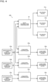
- Fig. 4 is a function block diagram of the air-conditioning apparatus 100 according to Embodiment 1. As illustrated in Fig.
- each of the refrigerant leak detecting sensors 23a to 23c detects occurrence of a refrigerant leak from an associated one of the heat load apparatuses 2a to 2c, it transmits a detection signal indicating the occurrence of the refrigerant leak from the associated heat load apparatus 2a, 2b, or 2c to an associated one of the load-side controllers 25a to 25c.
- each of the load-side controllers 25a to 25c receives the detection signal from an associated one of the refrigerant leak detecting sensors 23a to 23c.
- the load-side controller 25a, 25b, or 25c transmits a leak occurrence signal to the heat-source-side controller 19.
- the load-side controller 25a, 25b, or 25c closes an associated one of the load-side expansion valves 22a to 22c.
- associated ones of the load-side controllers 25a to 25c increase the opening degrees of respective associated ones of the load-side expansion valves 22a to 22c from the present opening degrees on the basis of an instruction from the heat-source-side controller 19.
- the heat-source-side controller 19 When receiving a leak occurrence signal from any of the load-side controllers 25a to 25c, the heat-source-side controller 19 closes one of the solenoid valves 31a to 31c that is associated with the heat load apparatus 2a, 2b, or 2c in which a refrigerant leak occurs.
- the heat-source-side controller 19 instructs ones of the load-side controllers 25a to 25c that are associated with the others of the heat load apparatuses 2a to 2c, that is, the head load apparatuses in which a refrigerant leak does not occur, to increase the opening degrees of ones of the load-side expansion valves 22a to 22c that are provided in the above other heat load apparatuses.
- the heat-source-side controller 19 causes those associated load-side expansion valves to be fully opened, and in the case where the associated load-side expansion valves are fully opened, the source-side controller 19 keeps the associated load-side expansion valves in the fully opened state.
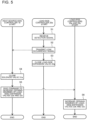
- Fig. 5 is a flow chart of the operations of the heat-source-side controller 19 and the load-side controllers 25a to 25c in Embodiment 1.
- a left flow is the flow of processing by the heat-source-side controller 19
- a center flow is the flow of processing by the load-side controller 25a
- a right flow is the flow of processing by the load-side controllers 25b and 25c.
- the description is made on the premise that the load-side expansion valves 22a to 22c of the heat load apparatuses 2a to 2c and the solenoid valves 31a to 31c of the shut-off devices 3a to 3c are all kept in the opened state until a refrigerant leak is detected.
- the opening degree of each of the load-side expansion valves 22a to 22c is less than the maximum opening degree; that is, the load-side expansion valve is not fully opened.
- the load-side controller 25a receives a detection signal from the refrigerant leak detecting sensor 23a (step S1). When receiving the detection signal, the load-side controller 25a transmits a leak occurrence signal to the heat-source-side controller 19 (step S2). The load-side controller 25a closes the load-side expansion valve 22a (step S3).
- the heat-source-side controller 19 When receiving the leak occurrence signal from the load-side controller 25a, the heat-source-side controller 19 closes the solenoid valve 31a associated with the heat load apparatus 2a in which the refrigerant leak occurs (step S4).
- the heat-source-side controller 19 instructs the load-side controllers 25b and 25c of the heat load apparatuses 2b and 2c in which a refrigerant leak does not occur to increase the opening degrees of the load-side expansion valves 22b and 22c of the heat load apparatuses 2b and 2c (step S5).
- the load-side controllers 25b and 25c increase the opening degrees of the load-side expansion valves 22b and 22c from the present opening degrees thereof (step S6). It should be noted that the step S2 and the step S3 may be interchanged.
- Embodiment 1 when a refrigerant leak occurs in the heat load apparatus 2a, 2b, or 2c, an associated one of the load-side expansion valves 22a to 22c and an associated one of the solenoid valves 31a to 31c are closed.
- the opening degrees of ones of the load-side expansion valves 22a to 22c that are associated with the others of the heat load apparatuses 2a to 2c, that is, the heat load apparatuses in which a refrigerant leak does occur are increased.
- the above description refers to by way of example the case where a refrigerant leak occurs in the heat load apparatus 2a but does not occur in the heat load apparatus 2b or the heat load apparatus 2c.
- the load-side expansion valve 22b or 22c and the solenoid valve 31b or 31c are controlled in the same manner as in the above case. That is, for example, in the case where a refrigerant leak occurs in the heat load apparatus 2b but does not occur in the heat load apparatus 2a or the heat load apparatus 2c, the load-side expansion valve 22b and the solenoid valve 31b are closed and the opening degrees of the load-side expansion valves 22a and 22c are increased from the present opening degrees.
- the load-side expansion valves 22a and 22b and the solenoid valves 31a and 31b are closed and the opening degree of the load-side expansion valve 22c is increased from the present opening degree.
- Fig. 6 is an explanatory view for controls of the opening degrees of the load-side expansion valves of Embodiment 1 and the comparative example in the case where a refrigerant leak occurs.
- Fig. 6 is an explanatory view for controls of the opening degrees of the load-side expansion valves of Embodiment 1 and the comparative example in the case where a refrigerant leak occurs.
- outlined triangles indicate respective values of the opening degree [pulse] of one of the load-side expansion valves 22a to 22c that is provided in the heat load apparatus 2a, 2b, or 2c from which a refrigerant leak is detected, the values of the above opening degree being measured at respective times [s] that elapse from detection of the refrigerant leak; and black triangles indicate those of each of ones of the load-side expansion valves 22a to 22c that are provided in the others of the heat load apparatuses 2a to 2c, that is, the heat load apparatuses from which a refrigerant leak is not detected and that are in a normal state.
- outlined circles indicate those of a load-side expansion valve of a heat load apparatus from which a refrigerant leak is detected; and black circles indicate those of each of load-side expansion valves of heat load apparatuses that are in the normal state.
- the air-conditioning apparatus of the comparative example is similar in configuration to the air-conditioning apparatus 100 of Embodiment 1, but is different in control from the air-conditioning apparatus 100 of Embodiment 1.
- a load-side expansion valve and a solenoid valve that are associated with a heat load apparatus in which a refrigerant leak occurs are closed; however, the opening degree of each of load-side expansion valves of heat load apparatuses in which a refrigerant leak does not occur is kept at a certain opening degree that is less than the maximum opening degree; that is, the load-side expansion valve is not fully opened.
- Fig. 7 is an explanatory view for the amount of a refrigerant leak in each of Embodiment 1 and the comparative example.
- black triangles indicate respective values of a refrigerant leak amount QI [g/s] that were measured at elapsed times [s] after detection of a refrigerant leak; and regarding the comparative example, black circles indicate respective values of the refrigerant leak amount QI [g/s].
- the air-conditioning apparatus of the comparative example when the load-side expansion valve of a heat load apparatus from which a refrigerant leak is detected is closed, the opening degrees of the load-side expansion valves of heat load apparatuses from which a refrigerant leak is not detected are unchanged.
- the total area of flow passages in all the heat load apparatuses is reduced.
- the load-side expansion valve of the heat load apparatus from which a refrigerant leak is detected is being closed, the pressures at the inlets of the load-side expansion valves rise.
- the difference between the pressures at the inlet and outlet of the load-side expansion valve of each of the heat load apparatuses increases and the amount of refrigerant that passes through the load-side expansion valve of the heat load apparatus from which the refrigerant leak is detected also increases.
- the amount of the refrigerant leak increase until the load-side expansion valve of the heat load apparatus from which the refrigerant leak is detected is fully closed, and as a result, the amount of the refrigerant leak is larger than that in Embodiment 1.
- Embodiment 1 in the case where a refrigerant leak occurs in the heat load apparatus 2a, 2b, or 2c, an associated one of the load-side expansion valves 22a to 22c and an associated one of the solenoid valves 31a to 31c are closed.
- the opening degrees of associated ones of the load-side expansion valves 22a to 22c are increased from the present opening degrees.
- the total area of the flow passages in all the heat load apparatuses 2a to 2c is kept constant.
- the pressures at the inlets of the load-side expansion valves 22a to 22c do not rise.
- Embodiment 1 it is possible to reduce the amount of refrigerant that leaks until the load-side expansion valve 22a, 22b, or 22c provided in the heat load apparatus 2a, 2b, or 2c in which the refrigerant leak occurs is fully closed.
- Embodiment 1 in the case where a refrigerant leak occurs in the heat load apparatus 2a, 2b, or 2c, an associated one of the load-side expansion valves 22a to 22c and an associated one of the solenoid valves 31a to 31c are closed, and for the others of the heat load apparatuses 2a to 2c, that is, the heat load apparatuses in which a refrigerant leak does not occur, the opening degrees of associated ones of the load-side expansion valves 22a to 22c are increased from the present opening degrees.
- Embodiment 1 in the air-conditioning apparatus 100 in which the heat load apparatuses 2a to 2c and the heat source apparatus 1 are connected in parallel, it is possible to reduce the amount of a refrigerant leak in the case where the refrigerant leak occurs in any of the heat load apparatuses 2a to 2c.
- Embodiment 1 in the case where a refrigerant leak occurs in the heat load apparatus 2a, 2b, or 2c, the flow of refrigerant to and from the heat load apparatus 2a, 2b, or 2c in which the refrigerant leak occurs is shut off, and the others of the heat load apparatuses 2a to 2c, that is, the heat load apparatuses in which a refrigerant leak does not occur, can thus continue to operate. It is therefore possible to reduce the likelihood of impairment of the comfort in the target spaces in which the heat load apparatuses 2a to 2c are installed.
- Embodiment 1 it is described above that in the case where a refrigerant leak occurs in the heat load apparatus 2a, 2b, or 2c, in the others of the heat load apparatuses 2a to 2c, that is, the heat load apparatuses in which a refrigerant leak does not occur, the opening degrees of associated ones of the load-side expansion valves 22a to 22c are increased from the present opening degrees.
- any one of the associated ones of the load-side expansion valves 22a to 22c may be increased in opening degree as long as the total area of the flow passages in all the heat load apparatuses 2a to 2c is kept constant.
- Embodiment 2 when a refrigerant leak in any of the heat load apparatuses 2a to 2c is detected, the opening degree of the heat-source-side expansion valve 13 is decreased from the present opening degree.
- Embodiment 2 is different from Embodiment 1.
- components that are the same as those in Embodiment 1 will be denoted by the same reference signs, and their descriptions will thus be omitted.
- the following description concerning Embodiment 2 is made by referring mainly to the differences between Embodiments 1 and 2.
- the air-conditioning apparatus 100 according to Embodiment 2 has the same configuration as the air-conditioning apparatus 100 according to Embodiment 1.
- the following description concerning advantages obtained in Embodiment 2 is made by referring to the differences between Embodiment 2 and the comparative example.
- Fig. 8 is an explanatory view for the control of the heat-source-side expansion valve 13 in Embodiment 2 in the case where a refrigerant leak occurs. In Fig.
- outlined circles indicate respective values of the opening degree [pulse] of the heat-source-side expansion valve 13 in the heat source apparatus 1 from which a refrigerant leak is detected, the values of the opening degree [pulse] being measured at elapsed times [s] after detection of the refrigerant leak.
- the configuration and control of the air-conditioning apparatus of the comparative example are the same as those in Embodiment 1, and their detailed descriptions will thus be omitted. As illustrated in Fig.
- the heat-source-side controller 19 in the cooling operation, in the case where a refrigerant leak in any of the heat load apparatuses 2a to 2c is detected, the heat-source-side controller 19 according to Embodiment 2 decreases the opening degree of the heat-source-side expansion valve 13 from the present opening degree, in addition to the control described regarding Embodiment 1.
- Fig. 9 is an explanatory view for the amount of a refrigerant leak in each of Embodiment 2 and the comparative example.
- black squares indicate respective values of a refrigerant leak amount QI [g/s] that were measured at elapsed times [s] after detection of a refrigerant leak; and regarding the comparative example, black circles indicate respective values of the refrigerant leak amount QI [g/s].
- the refrigerant at the inlets of the load-side expansion valves 22a to 22c flows as liquid refrigerant.
- Embodiment 2 in the case where the opening degree of the heat-source-side expansion valve 13 of the heat source apparatus 1 is decreased, the refrigerant at the inlets of the load-side expansion valves 22a to 22c flows as two-phase refrigerant. It should be noted that the density of the two-phase refrigerant is lower than that of the liquid refrigerant. Thus, in the case where two-phase refrigerant and liquid refrigerant that pass through the load-side expansion valves 22a to 22c whose opening degrees are set at a given value have the same volume, the weight of the two-phase refrigerant is smaller than that of the liquid refrigerant. Therefore, in Embodiment 2, the amount of the refrigerant leak can be reduced to a smaller value than in the comparative example.
- the order in which the operations of the heat-source-side controller 19 and the load-side controllers 25a to 25c are performed corresponds to an order that is determined such that a process in which the heat-source-side controller 19 decreases the opening degree of the heat-source-side expansion valve 13 from the present opening degree is executed after any of step S2 to step S6 described regarding Embodiment 1. This detailed description will thus be omitted.
- Embodiment 2 in the case where a refrigerant leak occurs in the heat load apparatus 2a, 2b, or 2c, an associated one of the load-side expansion valves 22a to 22c and an associated one of the solenoid valves 31a to 31c are closed, the opening degrees of ones of the load-side expansion valves 22a to 22c that are associated with the others of the heat load apparatuses 2a to 2c, that is, the heat load apparatuses in which a refrigerant leak does not occur, are increased from the present opening degrees.
- the amount of refrigerant that is supplied to the others of the heat load apparatuses 2a to 2c, that is the heat load apparatuses in which a refrigerant leak does not occur increases, and the amount of refrigerant that is supplied to the heat load apparatus 2a, 2b, or 2c in which the refrigerant leak occurs decreases. Therefore, according to Embodiment 2, in the air-conditioning apparatus 100 in which the heat load apparatuses 2a to 2c and the heat source apparatus 1 are connected in parallel, it is possible to reduce the amount of a refrigerant leak in the case where the refrigerant leak occurs in any of the heat load apparatuses 2a to 2c.
- the flow of refrigerant to and from the heat load apparatus 2a, 2b, or 2c in which the refrigerant leak occurs is shut off, and the others of the heat load apparatuses 2a to 2c, that is, the heat load apparatuses in which a refrigerant leak does not occur, can thus continue to operate. It is therefore possible to reduce the likelihood of impairment of the comfort in the target spaces in which the heat load apparatuses 2a to 2c are installed.
- Embodiment 2 in the case where a refrigerant leak in any of the heat load apparatuses 2a to 2c is detected, since the opening degree of the heat-source-side expansion valve 13 is decreased from the present opening degree, the refrigerant at the inlet of each of the load-side expansion valves 22a to 22c flows as two-phase refrigerant. Thus, the density of the refrigerant is reduced, and the amount of the refrigerant leak can thus be further decreased.
- Embodiment 3 in the case where a refrigerant leak in any of the heat load apparatuses 2a to 2c is detected, the volume of air from the fan 15 is reduced from the present volume of air.
- Embodiment 3 is different from Embodiment 1.
- components that are the same as those in Embodiment 1 will be denoted by the same reference signs, and their descriptions will thus be omitted.
- the following description concerning Embodiment 3 is made by referring manly to the differences between Embodiments 1 and 3.
- the air-conditioning apparatus 100 according to Embodiment 3 has the same configuration as the air-conditioning apparatus 100 according to Embodiment 1.
- the following description concerning advantages obtained in Embodiment 3 is made by comparing Embodiment 3 with the comparative example.
- the heat-source-side controller 19 reduces the volume of air from the fan 15 from the present volume of air in addition to the control described above regarding Embodiment 1, when a refrigerant leak in any of the heat load apparatuses 2a to 2c is detected.
- the configuration and the control of the air-conditioning apparatus of the comparative example are the same as those described regarding Embodiment 1, and their detail descriptions will thus be omitted.
- Fig. 10 is an explanatory view for the amount of a refrigerant leak in each of Embodiment 3 and the comparative example.
- black rhombuses indicate respective values of a refrigerant leak amount QI [g/s] that were measured at elapsed times [s] after detection of a refrigerant leak; and regarding the comparative example, black circles indicate respective values of the refrigerant leak amount QI [g/s].
- the volume of air from the fan 15 is decreased from the present volume of air, whereby the degree of supercooling of refrigerant that flows through the outlet of the refrigerant heat exchanger 12 is reduced, and the density of the refrigerant is reduced.
- the weight of the refrigerant the density of which is reduced is smaller than that of the refrigerant the density of which is not reduced. Therefore, as indicated in Fig. 10 , in Embodiment 3, the amount of the refrigerant leak can be reduced to a smaller value than in the comparative example.
- the order in which the operations of the heat-source-side controller 19 and the load-side controllers 25a to 25c are performed corresponds to an order that is determined such that a process in which the heat-source-side controller 19 reduces the volume of air from the fan 15 from the present volume of air is executed after any of step S2 to step S6 described regarding Embodiment 1. This detailed description will thus be omitted.
- Embodiment 3 in the case where a refrigerant leak occurs in the heat load apparatus 2a, 2b, or 2c, an associated one of the load-side expansion valves 22a to 22c and an associated one of the solenoid valves 31a to 31c are closed, and the opening degrees of ones of the load-side expansion valves 22a to 22c that are associated with the others of the heat load apparatuses 2a to 2c, that is, the heat load apparatuses in which a refrigerant leak does not occur, are increased from the present opening degrees.
- Embodiment 3 in the air-conditioning apparatus 100 in which the heat load apparatuses 2a to 2c and the heat source apparatus 1 are connected in parallel, it is possible to reduce the amount of a refrigerant leak in the case where the refrigerant leak occurs in any of the heat load apparatuses 2a to 2c.
- Embodiment 3 the flow of refrigerant to and from the heat load apparatus 2a, 2b, or 2c in which the refrigerant leak occurs is shut off, and the others of the heat load apparatuses 2a to 2c, that is, the heat load apparatuses in which a refrigerant leak does not occur, can thus continue to operate. It is therefore possible to reduce the likelihood of impairment of the comfort in the target spaces in which the heat load apparatuses 2a to 2c are installed.
- Embodiment 3 in the case where a refrigerant leak in any of the heat load apparatuses 2a to 2c is detected, the volume of air from the fan 15 is reduced from the present volume of air, and the degree of supercooling of refrigerant that flows through the outlet of the refrigerant heat exchanger 12 is thus reduced. Therefore, the density of the refrigerant is reduced, and the amount of the refrigerant leak can thus be further reduced.
- Embodiment 4 in the case where a refrigerant leak in any of the heat load apparatuses 2a to 2c is detected, the bypass valve 16 is opened.
- Embodiment 4 is different from Embodiment 1.
- components that are the same as those in Embodiment 1 will be denoted by the same reference signs, and their descriptions will thus be omitted.
- the following description concerning Embodiment 4 is made by referring mainly to the differences between Embodiments 1 and 4.
- the air-conditioning apparatus 100 according to Embodiment 4 has the same configuration as the air-conditioning apparatus 100 according to Embodiment 1.
- the following description concerning advantages obtained in Embodiment 4 is made by comparing Embodiment 4 with the comparative example.
- the heat-source-side controller 19 performs control to open the bypass valve 16 in addition to the control described regarding Embodiment 1, when a refrigerant leak in any of the heat load apparatuses 2a to 2c is detected.
- the configuration and the control of the air-conditioning apparatus of the comparative example are the same as those described regarding Embodiment 1, and their detail descriptions will thus be omitted.
- Fig. 11 is an explanatory view for the amount of a refrigerant leak in each of Embodiment 4 and the comparative example.
- outlined triangles indicate respective values of a refrigerant leak amount QI [g/s] that were measured at elapsed times [s] after detection of a refrigerant leak; and regarding the comparative example, black circles indicate respective values of the refrigerant leak amount QI [g/s].
- the bypass valve 16 is opened, thereby reducing a discharge pressure of the compressor 10 and raising a suction pressure of the compressor 10. As a result, the difference between the pressures at the outlet and inlet of each of the load-side expansion valves 22a to 22c is reduced.
- the order in which the operations of the heat-source-side controller 19 and the load-side controllers 25a to 25c are performed corresponds to an order that is determined such that a process in which the heat-source-side controller 19 opens the bypass valve 16 is executed after any of step S2 to step S6 described regarding Embodiment 1. This detailed description will thus be omitted.
- Embodiment 4 in the case where a refrigerant leak occurs in the heat load apparatus 2a, 2b, or 2c, an associated one of the load-side expansion valves 22a to 22c and an associated one of the solenoid valves 31a to 31c are closed, and regarding the others of the heat load apparatuses 2a to 2c, that is, the heat load apparatuses in which a refrigerant leak does not occur, the opening degrees of associated ones of the load-side expansion valves 22a to 22c are increased from the present opening degrees.
- Embodiment 4 the flow of refrigerant to and from the heat load apparatus 2a, 2b, or 2c in which a refrigerant leak occurs is shut off, and the others of the heat load apparatuses 2a to 2c, that is, the heat load apparatuses in which a refrigerant leak does not occur, can thus continue to operate. It is therefore possible to reduce the likelihood of impairment of the comfort in the target spaces in which the heat load apparatuses 2a to 2c are installed.
- Embodiment 4 in the case where a refrigerant leak in any of the heat load apparatuses 2a to 2c is detected, the bypass valve 16 is opened. Thus, the difference between the pressures at the outlet and inlet of each of the load-side expansion valves 22a to 22c is reduced. As a result, the amount of refrigerant that flows through the load-side expansion valve 22a, 22b, or 22c that is provided in the heat load apparatus 2a, 2b, or 2c from which the refrigerant leak is detected is reduced, and the amount of the refrigerant leak can thus be further reduced.
- Embodiment 5 in the case where a refrigerant leak in any of the heat load apparatuses 2a to 2c is detected, the operating frequency of the compressor 10 is reduced from the present operating frequency.
- Embodiment 5 is different from Embodiment 1.
- components that are the same as those in Embodiment 1 will be denoted by the same reference signs, and their descriptions will thus be omitted.
- the following description concerning Embodiment 5 is made by referring mainly to the differences between Embodiments 1 and 5.
- the air-conditioning apparatus 100 according to Embodiment 5 has the same configuration as the air-conditioning apparatus 100 according to Embodiment 1.
- the following description concerning advantages obtained in Embodiment 5 is made by comparing Embodiment 5 with the comparative example.
- the heat-source-side controller 19 according to Embodiment 5 performs control to reduce the operating frequency of the compressor 10 from the present operating frequency in addition to the control described regarding Embodiment 1, in the case where a refrigerant leak in any of the heat load apparatuses 2a to 2c is detected.
- the configuration and control of the air-conditioning apparatus of the comparative example are the same as those described above regarding Embodiment 1, and their detailed descriptions will thus be omitted.
- Fig. 12 is an explanatory view for the amount of a refrigerant leak in each of Embodiment 5 and the comparative example.
- outlined squares indicate respective values of a refrigerant leak amount QI [g/s] that were measured at elapsed times [s] after detection of a refrigerant leak; and regarding the comparative example, black circles indicate respective values of the refrigerant leak amount QI [g/s].
- the operating frequency of the compressor 10 is reduced from the present operating frequency, thereby reducing the discharge pressure of the compressor 10 and raising the suction pressure of the compressor 10.
- the order in which the operations of the heat-source-side controller 19 and the load-side controllers 25a to 25c are performed corresponds to an order that is determined such that a process in which the heat-source-side controller 19 reduces the operating frequency of the compressor 10 from the present operating frequency is executed after any of step S2 to step S6 described regarding Embodiment 1. This detailed description will thus be omitted.
- Embodiment 5 in the case where a refrigerant leak occurs in the heat load apparatus 2a, 2b, or 2c, an associated one of the load-side expansion valves 22a to 22c and an associated one of the solenoid valves 31a to 31c are closed, and regarding the others of the heat load apparatuses 2a to 2c, that is, the heat load apparatuses in which a refrigerant leak does not occur, the opening degrees of associated ones of the load-side expansion valves 22a to 22c are increased from the present opening degrees.
- Embodiment 5 in the air-conditioning apparatus 100 in which the heat load apparatuses 2a to 2c and the heat source apparatus 1 are connected in parallel, it is possible to reduce the amount of a refrigerant leak in the case where the refrigerant leak occurs in any of the heat load apparatuses 2a to 2c.
- Embodiment 5 the flow of refrigerant to and from the heat load apparatus 2a, 2b, or 2c in which a refrigerant leak occurs is shut off, and the others of the heat load apparatuses 2a to 2c, that is, the heat load apparatuses in which a refrigerant leak does not occur, can thus continue to operate. It is therefore possible to reduce the likelihood of impairment of the comfort in the target spaces in which the heat load apparatuses 2a to 2c are installed.
- Embodiment 5 in the case where a refrigerant leak in any of the heat load apparatuses 2a to 2c is detected, the operating frequency of the compressor 10 is reduced from the present operating frequency, thereby reducing the difference between the pressures at the outlet and inlet of each of the load-side expansion valves 22a to 22c.
- the amount of refrigerant that flows through the load-side expansion valve 22a, 22b, or 22c that is provided in the heat load apparatus 2a, 2b, or 2c from which the refrigerant leak is detected is reduced. Therefore, it is possible to further reduce the amount of the refrigerant leak.
- Fig. 13 is a circuit diagram of an air-conditioning apparatus 100A according to Embodiment 6.
- a refrigerant to heat-medium heat exchanger 12A is provided instead of the fan 15 and the refrigerant heat exchanger 12, and a pump 41, a flow control valve 42, a heat-medium heat exchanger 43, and a heat-medium pipe 44 are provided.
- Embodiment 6 is different from Embodiment 1.
- components that are the same as those in Embodiment 1 will be denoted by the same reference signs, and their descriptions will thus be omitted.
- the following description concerning Embodiment 6 is made by referring mainly to the differences between Embodiments 1 and 6.
- the heat source apparatus 1 of the air-conditioning apparatus 100A includes the refrigerant to heat-medium heat exchanger 12A instead of the fan 15 and the refrigerant heat exchanger 12.
- the refrigerant to heat-medium heat exchanger 12A of the heat source apparatus 1 includes a refrigerant flow passage (not illustrated) through which refrigerant that circulates in the refrigerant circuit 6 flows and a heat-medium flow passage (not illustrated) through which a heat medium that circulates in a heat-medium circuit 7 flows, and causes heat exchange to be performed between the refrigerant and the heat medium.
- the pump 41, the flow control valve 42, the heat-medium heat exchanger 43, and the heat-medium flow passage in the refrigerant to heat-medium heat exchanger 12A are connected by the heat-medium pipes 44, whereby the heat-medium circuit 7 is formed.
- the pump 41 is provided at the heat-medium pipe 44 to transfer the heat medium to the refrigerant to heat-medium heat exchanger 12A.
- the flow control valve 42 is provided at the heat-medium pipe 44 to adjust the flow rate of the heat medium that circulates in the heat-medium circuit 7.
- the heat-medium heat exchanger 43 causes heat exchange to be performed between the heat medium and air, and supplies heating energy or cooling energy to the heat medium.
- the heat medium is a fluid that differs from the refrigerant, and is, for example, water.
- the refrigerant to heat-medium heat exchanger 12A of Embodiment 6 is a water cooled heat exchanger that causes heat exchange to be performed between the refrigerant and a heat medium subjected to heat exchange at the heat-medium heat exchanger 43, not an air cooled heat exchanger that causes heat exchange to be performed between the refrigerant and air as in Embodiment 1.
- the heat-source-side controller 19 of Embodiment 6 controls the operations of the pump 41 and the flow control valve 42, which are connected to the heat-source-side controller 19 by wire or wirelessly.
- the heat-source-side controller 19 controls the operating frequency of the pump 41 and the opening degree of the flow control valve 42 based on the results of detection by the sensors described regarding Embodiment 1.
- the heat-source-side controller 19 of Embodiment 6 performs the control described regarding Embodiment 1 when a refrigerant leak in any of the heat load apparatuses 2a to 2c is detected.
- Fig. 14 is an explanatory view for the cooling operation of the air-conditioning apparatus 100A according to Embodiment 6.
- Fig. 15 is an explanatory view for the heating operation of the air-conditioning apparatus 100A according to Embodiment 6.
- the flows of refrigerant in the refrigerant circuit 6 in the cooling operation and the heating operation are the same as those in Embodiment 1, and their descriptions will thus be omitted.
- Embodiment 6 in the case where a refrigerant leak occurs in the heat load apparatus 2a, 2b, or 2c, an associated one of the load-side expansion valves 22a to 22c and an associated one of the solenoid valves 31a to 31c are closed, and regarding the others of the heat load apparatuses 2a to 2c, that is, the heat load apparatuses in which a refrigerant leak does not occur, the opening degree of associated ones of the load-side expansion valves 22a to 22c are increased from the opening degrees.
- Embodiment 6 in the air-conditioning apparatus 100A in which the heat load apparatuses 2a to 2c and the heat source apparatus 1 are connected in parallel, it is possible to reduce the amount of a refrigerant leak in the case where the refrigerant leak occurs in any of the heat load apparatuses 2a to 2c.
- Embodiment 6 the flow of refrigerant to and from the heat load apparatus 2a, 2b, or 2c in which a refrigerant leak occurs is shut off, and the others of the heat load apparatuses 2a to 2c, that is, the heat load apparatuses in which a refrigerant leak does not occur, can thus continue to operate. It is therefore possible to reduce the likelihood of impairment of the comfort in the target spaces in which the heat load apparatuses 2a to 2c are installed.
- the heat-source-side controller 19 of Embodiment 6 may be configured to perform not only the control described regarding Embodiment 1 but also the control described regarding Embodiment 2, 4, or 5. Furthermore, instead of reducing the volume of air from the fan 15 from the present volume of air as in Embodiment 3, the operating frequency of the pump 41 may be reduced from the present operating frequency or the opening degree of the flow control valve 42 may be reduced from the present opening degree. Also, in this case, it is possible to obtain similar advantages to those in Embodiment 3.
- Embodiments 1 to 6 each refer to by way of the case which in the heat load apparatuses 2a to 2c, the cooling operation and the heating operation cannot be performed at the same time.
- the present disclosure is also applicable to the case where the cooling operation and the heating operation can be performed at the same time.
- a single device or a plurality of devices that control the solenoid valves 31a to 31c of the shut-off devices 3a to 3c or the load-side expansion valves 22a to 22c correspond to "controller” or “controllers” of the present disclosure.
- the above descriptions concerning Embodiments 1 to 6 refer to by way of example the case where as the "controller” or “controllers”, the heat-source-side controller 19 controls the solenoid valves 31a to 31c of the shut-off devices 3a to 3c, and the load-side controllers 25a to 25c control the load-side expansion valves 22a to 22c.
- the heat-source-side controller 19 or any of the load-side controllers 25a to 25c may be omitted, and the "controller” or “controllers” may be made to have all functions of controlling the load-side expansion valves 22a to 22c and the solenoid valves 31a to 31c.
- the heat-source-side controller 19 and the load-side controllers 25a to 25c may be provided outside the housings of the heat source apparatus 1 and the heat load apparatuses 2a to 2c.
Landscapes
- Engineering & Computer Science (AREA)
- Mechanical Engineering (AREA)
- General Engineering & Computer Science (AREA)
- Physics & Mathematics (AREA)
- Thermal Sciences (AREA)
- Chemical & Material Sciences (AREA)
- Combustion & Propulsion (AREA)
- Air Conditioning Control Device (AREA)
Applications Claiming Priority (1)
| Application Number | Priority Date | Filing Date | Title |
|---|---|---|---|
| PCT/JP2022/000489 WO2023135630A1 (fr) | 2022-01-11 | 2022-01-11 | Climatiseur |
Publications (1)
| Publication Number | Publication Date |
|---|---|
| EP4464952A1 true EP4464952A1 (fr) | 2024-11-20 |
Family
ID=87278580
Family Applications (1)
| Application Number | Title | Priority Date | Filing Date |
|---|---|---|---|
| EP22920157.9A Withdrawn EP4464952A1 (fr) | 2022-01-11 | 2022-01-11 | Climatiseur |
Country Status (4)
| Country | Link |
|---|---|
| US (1) | US20250003615A1 (fr) |
| EP (1) | EP4464952A1 (fr) |
| JP (1) | JPWO2023135630A1 (fr) |
| WO (1) | WO2023135630A1 (fr) |
Family Cites Families (9)
| Publication number | Priority date | Publication date | Assignee | Title |
|---|---|---|---|---|
| JP5517789B2 (ja) | 2010-07-02 | 2014-06-11 | 日立アプライアンス株式会社 | 空気調和機 |
| WO2015004747A1 (fr) * | 2013-07-10 | 2015-01-15 | 三菱電機株式会社 | Appareil à cycle frigorifique |
| JP6323214B2 (ja) * | 2014-06-27 | 2018-05-16 | ダイキン工業株式会社 | 冷暖同時運転型空気調和装置 |
| JP6274277B2 (ja) * | 2015-09-30 | 2018-02-07 | ダイキン工業株式会社 | 冷凍装置 |
| JP6269756B1 (ja) * | 2016-09-02 | 2018-01-31 | ダイキン工業株式会社 | 冷凍装置 |
| JP7215819B2 (ja) * | 2017-01-11 | 2023-01-31 | ダイキン工業株式会社 | 空気調和装置及び室内ユニット |
| JP6844663B2 (ja) * | 2019-07-09 | 2021-03-17 | ダイキン工業株式会社 | 水量調整装置 |
| JP6866906B2 (ja) * | 2019-07-12 | 2021-04-28 | ダイキン工業株式会社 | 冷凍サイクルシステム |
| ES3032786T3 (en) * | 2019-11-05 | 2025-07-24 | Daikin Ind Ltd | Air conditioners and use of an air conditioner |
-
2022
- 2022-01-11 JP JP2023573504A patent/JPWO2023135630A1/ja active Pending
- 2022-01-11 US US18/710,292 patent/US20250003615A1/en active Pending
- 2022-01-11 EP EP22920157.9A patent/EP4464952A1/fr not_active Withdrawn
- 2022-01-11 WO PCT/JP2022/000489 patent/WO2023135630A1/fr not_active Ceased
Also Published As
| Publication number | Publication date |
|---|---|
| JPWO2023135630A1 (fr) | 2023-07-20 |
| US20250003615A1 (en) | 2025-01-02 |
| WO2023135630A1 (fr) | 2023-07-20 |
Similar Documents
| Publication | Publication Date | Title |
|---|---|---|
| EP3680585B1 (fr) | Dispositif de climatisation | |
| EP3279580B1 (fr) | Dispositif de climatisation | |
| EP3545241B1 (fr) | Procédé de gestion de l'atténuation des défaillances de compresseur dans un système de compression de vapeur | |
| WO2014132650A1 (fr) | Appareil de climatisation | |
| EP2182304A1 (fr) | Dispositif à cycle de réfrigération et procédé permettant de commander le fonctionnement d'un tel dispositif | |
| EP3614070A1 (fr) | Climatiseur | |
| WO2008032558A1 (fr) | dispositif de réfrigération | |
| EP2420765A1 (fr) | Unité de source de chaleur | |
| US11725855B2 (en) | Air conditioning apparatus | |
| JP2017142038A (ja) | 冷凍サイクル装置 | |
| US11892209B2 (en) | Multi-air conditioner for heating and cooling including a shut-off valve between indoor and outdoor units and control method thereof | |
| US12510276B2 (en) | Air-conditioning apparatus | |
| JP2023503192A (ja) | 空気調和装置 | |
| EP3779308A1 (fr) | Dispositif de climatisation | |
| US12104818B2 (en) | Air-conditioning apparatus | |
| US20180328639A1 (en) | Refrigeration cycle apparatus | |
| EP2096377B1 (fr) | Appareil de refrigeration | |
| US20220214055A1 (en) | Outdoor unit and air-conditioning apparatus | |
| US11506427B2 (en) | Air conditioning apparatus | |
| GB2549897A (en) | Air conditioning device | |
| EP4464952A1 (fr) | Climatiseur | |
| EP4328525B1 (fr) | Dispositif à cycle frigorifique | |
| KR100502308B1 (ko) | 멀티 에어컨의 바이패스 장치 및 그 제어방법 | |
| EP4310416B1 (fr) | Système de climatisation multiple hybride | |
| KR20240031467A (ko) | 공기조화기 |
Legal Events
| Date | Code | Title | Description |
|---|---|---|---|
| STAA | Information on the status of an ep patent application or granted ep patent |
Free format text: STATUS: THE INTERNATIONAL PUBLICATION HAS BEEN MADE |
|
| PUAI | Public reference made under article 153(3) epc to a published international application that has entered the european phase |
Free format text: ORIGINAL CODE: 0009012 |
|
| STAA | Information on the status of an ep patent application or granted ep patent |
Free format text: STATUS: REQUEST FOR EXAMINATION WAS MADE |
|
| 17P | Request for examination filed |
Effective date: 20240620 |
|
| AK | Designated contracting states |
Kind code of ref document: A1 Designated state(s): AL AT BE BG CH CY CZ DE DK EE ES FI FR GB GR HR HU IE IS IT LI LT LU LV MC MK MT NL NO PL PT RO RS SE SI SK SM TR |
|
| STAA | Information on the status of an ep patent application or granted ep patent |
Free format text: STATUS: THE APPLICATION HAS BEEN WITHDRAWN |
|
| 18W | Application withdrawn |
Effective date: 20241125 |