EP4465546A2 - Procédés et appareil d'indication de puissance - Google Patents
Procédés et appareil d'indication de puissance Download PDFInfo
- Publication number
- EP4465546A2 EP4465546A2 EP24186877.7A EP24186877A EP4465546A2 EP 4465546 A2 EP4465546 A2 EP 4465546A2 EP 24186877 A EP24186877 A EP 24186877A EP 4465546 A2 EP4465546 A2 EP 4465546A2
- Authority
- EP
- European Patent Office
- Prior art keywords
- transmit
- power value
- terminal
- transmit antenna
- port
- Prior art date
- Legal status (The legal status is an assumption and is not a legal conclusion. Google has not performed a legal analysis and makes no representation as to the accuracy of the status listed.)
- Pending
Links
Images



Classifications
-
- H—ELECTRICITY
- H04—ELECTRIC COMMUNICATION TECHNIQUE
- H04W—WIRELESS COMMUNICATION NETWORKS
- H04W8/00—Network data management
- H04W8/22—Processing or transfer of terminal data, e.g. status or physical capabilities
- H04W8/24—Transfer of terminal data
-
- H—ELECTRICITY
- H04—ELECTRIC COMMUNICATION TECHNIQUE
- H04B—TRANSMISSION
- H04B17/00—Monitoring; Testing
- H04B17/10—Monitoring; Testing of transmitters
- H04B17/101—Monitoring; Testing of transmitters for measurement of specific parameters of the transmitter or components thereof
- H04B17/102—Power radiated at antenna
-
- H—ELECTRICITY
- H04—ELECTRIC COMMUNICATION TECHNIQUE
- H04B—TRANSMISSION
- H04B7/00—Radio transmission systems, i.e. using radiation field
- H04B7/02—Diversity systems; Multi-antenna system, i.e. transmission or reception using multiple antennas
- H04B7/04—Diversity systems; Multi-antenna system, i.e. transmission or reception using multiple antennas using two or more spaced independent antennas
- H04B7/0413—MIMO systems
- H04B7/0456—Selection of precoding matrices or codebooks, e.g. using matrices antenna weighting
- H04B7/046—Selection of precoding matrices or codebooks, e.g. using matrices antenna weighting taking physical layer constraints into account
- H04B7/0465—Selection of precoding matrices or codebooks, e.g. using matrices antenna weighting taking physical layer constraints into account taking power constraints at power amplifier or emission constraints, e.g. constant modulus, into account
-
- H—ELECTRICITY
- H04—ELECTRIC COMMUNICATION TECHNIQUE
- H04B—TRANSMISSION
- H04B7/00—Radio transmission systems, i.e. using radiation field
- H04B7/02—Diversity systems; Multi-antenna system, i.e. transmission or reception using multiple antennas
- H04B7/04—Diversity systems; Multi-antenna system, i.e. transmission or reception using multiple antennas using two or more spaced independent antennas
- H04B7/06—Diversity systems; Multi-antenna system, i.e. transmission or reception using multiple antennas using two or more spaced independent antennas at the transmitting station
- H04B7/0613—Diversity systems; Multi-antenna system, i.e. transmission or reception using multiple antennas using two or more spaced independent antennas at the transmitting station using simultaneous transmission
- H04B7/0615—Diversity systems; Multi-antenna system, i.e. transmission or reception using multiple antennas using two or more spaced independent antennas at the transmitting station using simultaneous transmission of weighted versions of same signal
- H04B7/0619—Diversity systems; Multi-antenna system, i.e. transmission or reception using multiple antennas using two or more spaced independent antennas at the transmitting station using simultaneous transmission of weighted versions of same signal using feedback from receiving side
- H04B7/0636—Feedback format
- H04B7/0639—Using selective indices, e.g. of a codebook, e.g. pre-distortion matrix index [PMI] or for beam selection
-
- H—ELECTRICITY
- H04—ELECTRIC COMMUNICATION TECHNIQUE
- H04L—TRANSMISSION OF DIGITAL INFORMATION, e.g. TELEGRAPHIC COMMUNICATION
- H04L5/00—Arrangements affording multiple use of the transmission path
- H04L5/003—Arrangements for allocating sub-channels of the transmission path
- H04L5/0048—Allocation of pilot signals, i.e. of signals known to the receiver
-
- H—ELECTRICITY
- H04—ELECTRIC COMMUNICATION TECHNIQUE
- H04W—WIRELESS COMMUNICATION NETWORKS
- H04W52/00—Power management, e.g. Transmission Power Control [TPC] or power classes
- H04W52/04—Transmission power control [TPC]
- H04W52/06—TPC algorithms
- H04W52/14—Separate analysis of uplink or downlink
- H04W52/146—Uplink power control
-
- H—ELECTRICITY
- H04—ELECTRIC COMMUNICATION TECHNIQUE
- H04W—WIRELESS COMMUNICATION NETWORKS
- H04W52/00—Power management, e.g. Transmission Power Control [TPC] or power classes
- H04W52/04—Transmission power control [TPC]
- H04W52/18—TPC being performed according to specific parameters
- H04W52/28—TPC being performed according to specific parameters using user profile, e.g. mobile speed, priority or network state, e.g. standby, idle or non-transmission
-
- H—ELECTRICITY
- H04—ELECTRIC COMMUNICATION TECHNIQUE
- H04W—WIRELESS COMMUNICATION NETWORKS
- H04W52/00—Power management, e.g. Transmission Power Control [TPC] or power classes
- H04W52/04—Transmission power control [TPC]
- H04W52/30—Transmission power control [TPC] using constraints in the total amount of available transmission power
- H04W52/36—Transmission power control [TPC] using constraints in the total amount of available transmission power with a discrete range or set of values, e.g. step size, ramping or offsets
- H04W52/365—Power headroom reporting
-
- H—ELECTRICITY
- H04—ELECTRIC COMMUNICATION TECHNIQUE
- H04W—WIRELESS COMMUNICATION NETWORKS
- H04W52/00—Power management, e.g. Transmission Power Control [TPC] or power classes
- H04W52/04—Transmission power control [TPC]
- H04W52/30—Transmission power control [TPC] using constraints in the total amount of available transmission power
- H04W52/36—Transmission power control [TPC] using constraints in the total amount of available transmission power with a discrete range or set of values, e.g. step size, ramping or offsets
- H04W52/367—Power values between minimum and maximum limits, e.g. dynamic range
-
- H—ELECTRICITY
- H04—ELECTRIC COMMUNICATION TECHNIQUE
- H04W—WIRELESS COMMUNICATION NETWORKS
- H04W8/00—Network data management
- H04W8/22—Processing or transfer of terminal data, e.g. status or physical capabilities
-
- H—ELECTRICITY
- H04—ELECTRIC COMMUNICATION TECHNIQUE
- H04B—TRANSMISSION
- H04B7/00—Radio transmission systems, i.e. using radiation field
- H04B7/02—Diversity systems; Multi-antenna system, i.e. transmission or reception using multiple antennas
- H04B7/04—Diversity systems; Multi-antenna system, i.e. transmission or reception using multiple antennas using two or more spaced independent antennas
- H04B7/0404—Diversity systems; Multi-antenna system, i.e. transmission or reception using multiple antennas using two or more spaced independent antennas the mobile station comprising multiple antennas, e.g. to provide uplink diversity
-
- H—ELECTRICITY
- H04—ELECTRIC COMMUNICATION TECHNIQUE
- H04L—TRANSMISSION OF DIGITAL INFORMATION, e.g. TELEGRAPHIC COMMUNICATION
- H04L5/00—Arrangements affording multiple use of the transmission path
- H04L5/0001—Arrangements for dividing the transmission path
- H04L5/0014—Three-dimensional division
- H04L5/0023—Time-frequency-space
Definitions
- This application relates to the field of communications technologies, and in particular, to a power indication method and an apparatus.
- a base station In a process in which a terminal performs uplink transmission, a base station needs to perform power control on the terminal, so as to: avoid extremely low transmit power of the terminal and ensure quality of uplink data sent by the terminal; and avoid extremely high transmit power of the terminal and prevent interference to another terminal in a network.
- a terminal reports a power class (power classes) of the terminal to a network device, so that the network device performs power control on the terminal for uplink transmission.
- the power class defines a maximum transmit power value of the terminal that can be allowed by a network system in a same time unit on each frequency band.
- the network device cannot effectively perform power control on the terminal for uplink transmission only based on the power class reported by the terminal.
- This application provides a power indication method and apparatus, so that a network device can effectively perform power control on a terminal for uplink transmission, to ensure reliability of uplink transmission.
- a power indication method including: A terminal generates antenna transmit capability information, where the antenna transmit capability information is used to indicate whether a maximum transmit power value of each transmit antenna port of the terminal reaches a preset power value, or the antenna transmit capability information is used to indicate a maximum transmit power value of each transmit antenna port of the terminal; and the terminal sends the antenna transmit capability information to a network device.
- the network device may learn of power of each transmit antenna port of the terminal. In this way, when scheduling uplink transmission, the network device determines that a transmit power value that can be used by the terminal matches a transmit power value that is actually used by the terminal to perform uplink transmission, so as to ensure receiving performance of the network device.
- the antenna transmit capability information includes at least one of the following information: (1) an antenna configuration type, where the antenna configuration type is used to indicate a quantity of transmit antenna ports configured for the terminal, and a maximum transmit power value of each transmit antenna port; (2) a maximum transmit power value of each transmit antenna port; (3) a quantity of transmit antenna ports configured for the terminal and a quantity of transmit antenna ports whose maximum transmit power value reaches a preset power value; or (4) power indication information of each transmit antenna port, where the power indication information is used to indicate whether a maximum transmit power value of the transmit antenna port reaches a preset power value.
- the transmit antenna port is represented by using sounding reference signal (sounding reference signal, SRS) port information; or the transmit antenna port is represented by using SRS port information in combination with group information of a transmit antenna group.
- sounding reference signal sounding reference signal, SRS
- the transmit antenna port is configured to send a PUSCH.
- a power indication method including: A network device receives antenna transmit capability information sent by a terminal, where the antenna transmit capability information is used to indicate whether a maximum transmit power value of each transmit antenna port of the terminal reaches a preset power value, or the antenna transmit capability information is used to indicate a maximum transmit power value of each transmit antenna port of the terminal; and the network device determines, based on the antenna transmit capability information, whether the maximum transmit power value of each transmit antenna port of the terminal reaches the preset power value. Based on the foregoing technical solution, the network device may determine power of each transmit antenna port of the terminal. In this way, when scheduling uplink transmission, the network device determines that a transmit power value that can be used by the terminal matches a transmit power value that is actually used by the terminal to perform uplink transmission, so as to ensure receiving performance of the network device.
- the antenna transmit capability information includes at least one of the following information: (1) an antenna configuration type, where the antenna configuration type is used to indicate a quantity of transmit antenna ports configured for the terminal, and a maximum transmit power value of each transmit antenna port; (2) a maximum transmit power value of each transmit antenna port; (3) a quantity of transmit antenna ports configured for the terminal and a quantity of transmit antenna ports whose maximum transmit power value reaches a preset power value; or (4) power indication information of each transmit antenna port, where the power indication information is used to indicate whether a maximum transmit power value of the transmit antenna port reaches a preset power value.
- the transmit antenna port is represented by using SRS port information; or the transmit antenna port is represented by using SRS port information in combination with group information of a transmit antenna group.
- the transmit antenna port is configured to send a PUSCH.
- a terminal including: a processing module, configured to generate antenna transmit capability information, where the antenna transmit capability information is used to indicate whether a maximum transmit power value of each transmit antenna port of the terminal reaches a preset power value, or the antenna transmit capability information is used to indicate a maximum transmit power value of each transmit antenna port of the terminal; and a communications module, configured to send the antenna transmit capability information to a network device.
- the antenna transmit capability information includes at least one of the following information: (1) an antenna configuration type, where the antenna configuration type is used to indicate a quantity of transmit antenna ports configured for the terminal, and a maximum transmit power value of each transmit antenna port; (2) a maximum transmit power value of each transmit antenna port; (3) a quantity of transmit antenna ports configured for the terminal and a quantity of transmit antenna ports whose maximum transmit power value reaches a preset power value; or (4) power indication information of each transmit antenna port, where the power indication information is used to indicate whether a maximum transmit power value of the transmit antenna port reaches a preset power value.
- the transmit antenna port is represented by using SRS port information; or the transmit antenna port is represented by using SRS port information in combination with group information of a transmit antenna group.
- the transmit antenna port is configured to send a PUSCH.
- a terminal including: a processor, configured to generate antenna transmit capability information, where the antenna transmit capability information is used to indicate whether a maximum transmit power value of each transmit antenna port of the terminal reaches a preset power value, or the antenna transmit capability information is used to indicate a maximum transmit power value of each transmit antenna port of the terminal; and a communications interface, configured to send the antenna transmit capability information to a network device.
- the antenna transmit capability information includes at least one of the following information: (1) an antenna configuration type, where the antenna configuration type is used to indicate a quantity of transmit antenna ports configured for the terminal, and a maximum transmit power value of each transmit antenna port; (2) a maximum transmit power value of each transmit antenna port; (3) a quantity of transmit antenna ports configured for the terminal and a quantity of transmit antenna ports whose maximum transmit power value reaches a preset power value; or (4) power indication information of each transmit antenna port, where the power indication information is used to indicate whether a maximum transmit power value of the transmit antenna port reaches a preset power value.
- the transmit antenna port is represented by using SRS port information; or the transmit antenna port is represented by using SRS port information in combination with group information of a transmit antenna group.
- the transmit antenna port is configured to send a PUSCH.
- a terminal including a processor, where the processor is configured to: couple to a memory, read an instruction in the memory, and implement the power indication method in any one of the first aspect according to the instruction.
- a computer-readable storage medium stores an instruction, and when the computer-readable storage medium runs on a computer, the computer may perform the power indication method in any one of the first aspect.
- a computer program product that includes an instruction is provided, where when the computer program product runs on a computer, the computer may perform the power indication method in any one of the first aspect.
- a chip system configured to support a terminal in implementing a function of the power indication method in any one of the first aspect.
- the chip system further includes a memory, and the memory is configured to store a program instruction and data that are necessary for the terminal.
- the chip system may include a chip, or include a chip and another discrete device.
- a network device including: a communications module, configured to receive antenna transmit capability information sent by a terminal, where the antenna transmit capability information is used to indicate whether a maximum transmit power value of each transmit antenna port of the terminal reaches a preset power value, or the antenna transmit capability information is used to indicate a maximum transmit power value of each transmit antenna port of the terminal; and a processing module, configured to determine, based on the antenna transmit capability information, whether the maximum transmit power value of each transmit antenna port of the terminal reaches the preset power value.
- the antenna transmit capability information includes at least one of the following information: (1) an antenna configuration type, where the antenna configuration type is used to indicate a quantity of transmit antenna ports configured for the terminal, and a maximum transmit power value of each transmit antenna port; (2) a maximum transmit power value of each transmit antenna port; (3) a quantity of transmit antenna ports configured for the terminal and a quantity of transmit antenna ports whose maximum transmit power value reaches a preset power value; or (4) power indication information of each transmit antenna port, where the power indication information is used to indicate whether a maximum transmit power value of the transmit antenna port reaches a preset power value.
- the transmit antenna port is represented by using SRS port information; or the transmit antenna port is represented by using SRS port information in combination with group information of a transmit antenna group.
- the transmit antenna port is configured to send a PUSCH.
- a network device including: a communications interface, configured to receive antenna transmit capability information sent by a terminal, where the antenna transmit capability information is used to indicate whether a maximum transmit power value of each transmit antenna port of the terminal reaches a preset power value, or the antenna transmit capability information is used to indicate a maximum transmit power value of each transmit antenna port of the terminal; and a processor, configured to determine, based on the antenna transmit capability information, whether the maximum transmit power value of each transmit antenna port of the terminal reaches the preset power value.
- the antenna transmit capability information includes at least one of the following information: (1) an antenna configuration type, where the antenna configuration type is used to indicate a quantity of transmit antenna ports configured for the terminal, and a maximum transmit power value of each transmit antenna port; (2) a maximum transmit power value of each transmit antenna port; (3) a quantity of transmit antenna ports configured for the terminal and a quantity of transmit antenna ports whose maximum transmit power value reaches a preset power value; or (4) power indication information of each transmit antenna port, where the power indication information is used to indicate whether a maximum transmit power value of the transmit antenna port reaches a preset power value.
- the transmit antenna port is represented by using SRS port information; or the transmit antenna port is represented by using SRS port information in combination with group information of a transmit antenna group.
- the transmit antenna port is configured to send a PUSCH.
- a network device including a processor, where the processor is configured to: couple to a memory, read an instruction in the memory, and implement the power indication method in any one of the second aspect according to the instruction.
- a computer-readable storage medium stores an instruction, and when the computer-readable storage medium runs on a computer, the computer may perform the power indication method in any one of the second aspect.
- a computer program product that includes an instruction is provided, where when the computer program product runs on a computer, the computer may perform the power indication method in any one of the second aspect.
- a chip system configured to support a network device in implementing a function of the power indication method in any one of the second aspect.
- the chip system further includes a memory, and the memory is configured to store a program instruction and data that are necessary for the network device.
- the chip system may include a chip, or include a chip and another discrete device.
- a downlink resource of the system is divided into a plurality of orthogonal frequency division multiplexing (orthogonal frequency division multiple, OFDM) symbols in terms of time, and is divided into several subcarriers in terms of frequency.
- a physical downlink control channel (physical downlink control channel, PDCCH) in a downlink usually occupies the first two or three OFDM symbols in a subframe.
- the PDCCH is used to carry downlink control information (downlink control information, DCI).
- DCI downlink control information
- the DCI carries UE-specific resource allocation and other control information that is UE-specific or cell-shared.
- a physical uplink shared channel (physical uplink shared channel, PUSCH) in an uplink of the system is used to carry data for uplink sending.
- DFT-Spread OFDM DFT-S-OFDM
- Uplink transmission of NR supports two types of waveforms.
- a DFT-s-OFDM waveform is usually used, and the waveform supports data transmission of a single stream at most and ensures a single carrier characteristic.
- a cyclic prefix OFDM (cycle prefix OFDM, CP-OFDM) waveform is usually used, and the waveform supports single-stream or multi-stream data transmission to improve spectrum efficiency of a communications system.
- a terminal Before uplink transmission, a terminal reports a quantity of transmit antenna ports (for example, 1Tx, 2Tx, or 4Tx) that can be supported by the terminal.
- the quantity of transmit antenna ports may represent a maximum quantity of transport layers of uplink transmission.
- the quantity of transmit antenna ports also corresponds to a dimension of a precoding matrix that is indicated by DCI and that is used for current uplink transmission in codebook-based uplink transmission. That is, a quantity of rows of the precoding matrix represents a quantity of transmit antenna ports used for the current uplink transmission, and the quantity of rows is less than or equal to the quantity of transmit antenna ports that can be supported by the terminal.
- a quantity of columns of the precoding matrix represents the quantity of transport layers and is less than or equal to the quantity of transmit antenna ports that can be supported by the terminal. For example, for a terminal having 2Tx, a maximum quantity of transmit antenna ports used for uplink transmission is 2, and a maximum quantity of transport layers used for uplink transmission is 2.
- the transmit antenna port may be corresponding to a physical antenna port of the terminal, or a logical antenna port obtained after a physical antenna of the terminal is virtualized. Each transmit antenna port may be corresponding to one power amplifier (power amplifier, PA).
- the quantity of supported transmit antenna ports reported by the terminal also corresponds to a quantity of antenna ports in an SRS resource (that is, a quantity of SRS ports) transmitted based on a codebook, and the quantity of antenna ports in the SRS resource is usually less than or equal to the quantity of supported transmit antenna ports reported by the terminal.
- Antenna ports in each SRS resource may be in a one-to-one correspondence with transmit antenna ports used for uplink transmission, that is, an antenna port in each SRS resource is corresponding to one PA.
- a quantity of SRS ports may be configured as 2, and a maximum quantity of transport layers is 2.
- the terminal further reports a maximum coherent capability between antennas.
- a coherent capability includes a full-coherent (full-coherent) capability and a non-coherent (non-coherent) capability.
- a coherent capability includes a full-coherent capability, a partial-coherent (partial-coherent) capability, and a non-coherent capability.
- the full-coherent capability is used to indicate that all transmit antenna ports of a terminal for uplink transmission can complete phase alignment and perform phase weighting, that is, all the transmit antenna ports of the terminal can be used to send data of a same transport layer.
- the partial-coherent capability is used to indicate that there are two groups of transmit antenna ports in transmit antenna ports of a terminal used for uplink transmission.
- intra-group transmit antenna ports complete phase alignment, and can perform phase weighting to send data of a same transport layer.
- inter-group transmit antenna ports do not complete phase alignment, and cannot perform phase weighting.
- data of a same transport layer can only be transmitted by using one group of transmit antenna ports.
- the non-coherent capability means that phase alignment is not completed among all transmit antenna ports of a terminal. Therefore, all the transmit antenna ports of the terminal cannot be used to perform phase weighting and send data of a same transport layer, that is, data of one transport layer can only be sent by using one transmit antenna port of all the transmit antenna ports.
- codebooks pre-stored between a network device and a terminal may be shown in Table 1 to Table 7 below. Codewords in the codebook are arranged in ascending order of index values of transmission precoding matrix indicators (transmission precoding matrix indicator, TPMI) from left to right in the tables.
- TPMI transmission precoding matrix indicator
- One codebook may include three types of codewords, and each type of codeword corresponds to one coherent capability. For example, in Table 1, codewords whose TPMI index values are 0-1 correspond to the non-coherent capability, and codewords whose TPMI index values are 2-5 correspond to the full-coherent capability.
- a codeword whose TPMI index value is 0 corresponds to the non-coherent capability
- codewords whose TPMI index values are 1-2 correspond to the full-coherent capability.
- codewords whose TPMI index values are 0-3 correspond to the non-coherent capability
- codewords whose TPMI index values are 4-11 correspond to the partial-coherent capability
- codewords whose TPMI index values are 12-27 correspond to the full-coherent capability.
- codewords whose TPMI index values are 0-3 correspond to the non-coherent capability
- codewords whose TPMI index values are 4-11 correspond to the partial-coherent capability
- codewords whose TPMI index values are 12-27 correspond to the full-coherent capability.
- codewords whose TPMI index values are 0-5 correspond to the non-coherent capability
- codewords whose TPMI index values are 6-13 correspond to the partial-coherent capability
- codewords whose TPMI index values are 14-21 correspond to the full-coherent capability.
- a codeword whose TPMI index value is 0 corresponds to the non-coherent capability
- codewords whose TPMI index values are 1-2 correspond to the partial-coherent capability
- codewords whose TPMI index values are 3-6 correspond to the full-coherent capability.
- a codeword whose TPMI index value is 0 correspond to the non-coherent capability
- codewords whose TPMI index values are 1-2 correspond to the partial-coherent capability
- codewords whose TPMI index values are 3-4 correspond to the full-coherent capability.
- a terminal Before uplink transmission, a terminal sends an SRS on a corresponding time-frequency resource based on SRS resource configuration, and a base station receives and measures the SRS on the corresponding time-frequency resource to obtain uplink channel information. Based on the uplink channel information, the base station indicates, by using DCI carried on a PDCCH and used for scheduling uplink transmission, the terminal to send a PUSCH.
- the DCI indicates that transmission parameters of the PUSCH include a transmission rank indicator (transmission rank indicator, TRI) and a TPMI.
- transmission rank indicator transmission rank indicator
- TRI transmission rank indicator
- TPMI transmission rank indicator
- the base station may indicate a codeword of a full-coherent type, a partial-coherent type, or a non-coherent type.
- the base station may indicate a codeword of a partial-coherent type or a non-coherent type.
- the base station may indicate a codeword of a non-coherent type.
- the transmission parameters indicated by the DCI further include an SRS resource indication (SRS resource indication, SRI).
- SRS resource indication SRS resource indication, SRI.
- SRS resource indication SRI
- Each SRS resource is corresponding to one transmit antenna group, and one transmit antenna group includes a plurality of transmit antenna ports.
- the SRI is used to indicate, from a plurality of SRS resources, an SRS resource to be used by the terminal, that is, the SRI is used to indicate a transmit antenna group that needs to be used by the terminal. Therefore, the terminal may transmit the PUSCH by using transmit antenna ports included in the transmit antenna group indicated by the SRI.
- Each SRS port in the terminal is corresponding to one row of the foregoing precoding matrix, and an element in one row of the precoding matrix is a phase weighted coefficient of the corresponding SRS port. If values of elements in one row of the precoding matrix are all 0s, it indicates that the terminal does not need to send the PUSCH by using SRS ports corresponding to the row.
- the SRS port is a transmit antenna port used to transmit an SRS.
- the SRS port is a transmit antenna port that has SRS port information.
- SRS port information There is a correspondence between SRS port information and a sequence number of a row in the precoding matrix.
- the SRS port information may be an SRS port number, an SRS port identifier, or an SRS port index. Further, the SRS port information may further include another parameter related to the SRS port.
- a field used to indicate a quantity of transport layers of the PUSCH and the TPMI is a precoding information and number of layers field, and each bit field index value of the field is corresponding to a quantity of transport layers and a corresponding TPMI.
- Table 8 shows an example of a precoding information and number of layers field in a case of four transmit antennas, a CP-OFDM waveform, and a maximum quantity of transport layers being 2 to 4.
- Table 9 shows an example of a precoding information and number of layers field in a case of four transmit antennas, a CP-OFDM waveform, and a maximum quantity of transport layers being 1.
- TPMI 6 60
- TPMI 3 61
- TPMI 0 0
- TPMI 0 0
- TPMI 0 1
- TPMI 1 1
- TPMI 1 1
- TPMI 1 1
- TPMI 1 ... ... ... ... ... ... ... ...
- TPMI 3 3
- TPMI 3 3
- TPMI 3 4
- TPMI 4 4
- TPMI 4 ... ... ... ... 11
- TPMI 11 11
- TPMI 11 12
- TPMI 27 28-31
- the power class defines a maximum transmit power value of the terminal that can be allowed by a network system in a same time unit on each frequency band.
- Table 10 shows an example of a power class of the terminal.
- Table 10 EUTRAband Class 2 (dBm) Tolerance (dB) Class 3 (dBm) Tolerance (dB) n1 23 ⁇ 2 n2 23 ⁇ 23 n8 23 ⁇ 23 n12 23 ⁇ 23 n25 23 ⁇ 2 n34 23 ⁇ 2 n39 23 ⁇ 2 n40 23 ⁇ 2 n41 26 +2/-33 23 ⁇ 23 n66 23 ⁇ 2 n70 23 ⁇ 2 n71 23 +2 / -2.5 n77 26 +2/-3 23 +2/-3 n78 26 +2/-3 23 +2/-3 n79 26 +2/-3 23 +2/-3 n80 23 ⁇ 2 n81 23 ⁇ 2 n82 23 ⁇ 2 n83 23 ⁇ 2/-2.5 n84 23 ⁇ 2 n86 23 ⁇
- the power class can reflect only a maximum transmit power value of the terminal, and cannot reflect a maximum transmit power value of each transmit antenna port in the terminal.
- a Class 3 terminal there are at least two types of antenna configuration:
- an embodiment of this application provides a power indication method, including: A terminal generates antenna transmit capability information, where the antenna transmit capability information is used to indicate whether a maximum transmit power value of each transmit antenna port of the terminal reaches a preset power value, or the antenna transmit capability information is used to indicate a maximum transmit power value of each transmit antenna port of the terminal. Then, the terminal sends the antenna transmit capability information to a network device.
- the network device determines, based on the antenna transmit capability information, whether the maximum transmit power value of each transmit antenna port of the terminal reaches the preset power value (which may be directly determined based on the antenna transmit capability information; or the maximum transmit power value of each transmit antenna port of the terminal is first determined based on the antenna transmit capability information, and then whether the maximum transmit power value of each transmit antenna port of the terminal reaches the preset power value is determined based on the learned maximum transmit power value of each transmit antenna port).
- the network device comprehensively considers power of each transmit antenna port of the terminal, so that the network device indicates the terminal to perform uplink transmission by using a proper transmit antenna port, thereby ensuring system transmission performance.
- the network device expects the terminal to perform uplink transmission at a channel transmit power of 22 dBm. If the network device performs power control on uplink transmission only based on a power class reported by the terminal, the network device may indicate the terminal to perform uplink transmission by using a precoding matrix corresponding to a TPMI index value 0 in the codebook shown in Table 1. When the terminal performs uplink transmission by using the precoding matrix, actually, the terminal uses only the transmit antenna port 0 to perform uplink transmission. A maximum transmit power value of the transmit antenna port 0 is 20 dBm, and is less than 22 dBm. That is, actual transmit power of the terminal cannot reach the channel transmit power.
- the network device can learn that the transmit power value of the transmit antenna port 0 of the terminal is 20 dBm, and the transmit power value of the transmit antenna port 1 is 23 dBm. In this way, the network device can comprehensively consider power of each transmit antenna port of the terminal, so as to indicate the terminal to select an optimal transmit antenna port for uplink transmission. With reference to this example, the network device may determine that the transmit antenna port 1 is the optimal transmit antenna port.
- DCI delivered by the network device indicates the terminal to perform uplink transmission by using a precoding matrix corresponding to a TPMI index value 1 in the codebook shown in Table 1, that is, the network device indicates the terminal to perform uplink transmission by using the transmit antenna port 1.
- A/B may indicate A or B.
- the term “and/or” in this specification describes only an association relationship for associated objects and represents that three relationships may exist.
- a and/or B may represent the following three cases: Only A exists, both A and B exist, and only B exists.
- at least one refers to one or more
- plural of refers to two or more. Words such as “first” and “second” do not limit a quantity or an execution sequence, and words such as “first” and “second” do not mean being definitely different.
- the "indication" may include a direct indication and an indirect indication, or may include an explicit indication and an implicit indication.
- Information indicated by a piece of information is referred to as to-be-indicated information.
- the to-be-indicated information may be directly indicated, for example, the to-be-indicated information itself or an index of the to-be-indicated information.
- the to-be-indicated information may be indirectly indicated by indicating other information, where there is an association relationship between the other information and the to-be-indicated information.
- to-be-indicated information only a part of the to-be-indicated information may be indicated, and another part of the to-be-indicated information is known or agreed upon in advance.
- specific information may alternatively be indicated by using an arrangement order of all information that is agreed upon in advance (for example, specified in a protocol), thereby reducing indication overheads to some extent.
- the network architecture and the service scenario described in the embodiments of this application are intended to describe the technical solutions in the embodiments of this application more clearly, and do not constitute a limitation on the technical solutions provided in the embodiments of this application.
- a person of ordinary skill in the art may know that: With the evolution of the network architecture and the emergence of new service scenarios, the technical solutions provided in the embodiments of this application are also applicable to similar technical problems.
- the technical solutions provided in the embodiments of this application may be applied to various communications systems, for example, a long term evolution (long term evolution, LTE) communications system, an NR communications system using a 5th generation (5th generation, 5G) communications technology, a future evolved system, or a plurality of communications fusion systems.
- the technical solutions provided in this application may be applied to a plurality of application scenarios, such as machine to machine (machine to machine, M2M), macro-micro communications, enhanced mobile broadband (enhance mobile broadband, eMBB), ultra-reliable and low latency communications (ultra-reliable & low latency communication, uRLLC), and massive machine type communication (massive machine type communication, mMTC).
- FIG. 3 is a schematic diagram of a communications system to which the technical solutions provided in this application are applicable.
- a communications system 10 may include one or more network devices 20 (only one is shown) and one or more terminals 30 connected to each network device 20.
- FIG. 3 is only a schematic diagram, and does not constitute a limitation on an applicable scenario of the technical solutions provided in this application.
- the network device 20 may be a base station, a base station controller, or the like for wireless communication.
- the base station may include various types of base stations, for example, a micro base station (also referred to as a small cell), a macro base station, a relay node, and an access point. This is not specifically limited in the embodiments of this application.
- the base station may be a base transceiver station (base transceiver station, BTS) in a global system for mobile communications (global system for mobile communication, GSM) or code division multiple access (code division multiple access, CDMA), a NodeB (NodeB) in wideband code division multiple access (wideband code division multiple access, WCDMA), an evolved NodeB (evolutional NodeB, eNB or e-NodeB) in LTE, an eNB in an internet of things (internet of things, IoT) or narrow band-internet of things (narrow band-internet of things, NB-IoT), or a base station in a future 5G mobile communications network or a future evolved public land mobile network (public land Mobile Network, PLMN).
- GSM global system for mobile communication
- CDMA code division multiple access
- NodeB NodeB
- WCDMA wideband code division multiple access
- eNB evolved NodeB
- eNB evolved NodeB
- eNB evolved NodeB
- the terminal 30 is configured to provide a voice and/or data connectivity service to a user.
- the terminal 30 may have different names, for example, user equipment (user equipment, UE), an access terminal, a terminal unit, a terminal station, a mobile station, a mobile console, a remote station, a remote terminal, a mobile device, a wireless communications device, a terminal agent, a terminal apparatus, or the like.
- the terminal 30 may be various handheld devices, in-vehicle devices, wearable devices, and computers that have a communications function. This is not limited in the embodiments of this application.
- the handheld device may be a smartphone.
- the in-vehicle device may be an in-vehicle navigation system.
- the wearable device may be a smart band.
- the computer may be a personal digital assistant (personal digital assistant, PDA) computer, a tablet computer, and a laptop computer (laptop computer).
- FIG. 4 is a schematic diagram of a hardware structure of a network device 20 and a terminal 30 according to an embodiment of this application.
- the terminal 30 includes at least one processor 301.
- the terminal 30 further includes at least one memory 302 and at least one transceiver 303.
- the terminal 30 may further include an output device 304 and an input device 305.
- the processor 301, the memory 302, and the transceiver 303 are connected by using a bus.
- the processor 301 may be a general-purpose central processing unit (central processing unit, CPU), a microprocessor, an application-specific integrated circuit (application-specific integrated circuit, ASIC), or one or more integrated circuits for controlling program execution in the solution of this application.
- the processor 301 may also include a plurality of CPUs, and the processor 301 may be a single-core (single-CPU) processor or a multi-core (multi-CPU) processor.
- the processor herein may be one or more devices, circuits, or processing cores used for processing data (for example, a computer program instruction).
- the memory 302 may be a read-only memory (read-only memory, ROM) or another type of static storage device capable of storing static information and instructions, a random access memory (random access memory, RAM) or another type of dynamic storage device capable of storing information and instructions, or may be an electrically erasable programmable read-only memory (electrically erasable programmable read-only memory, EEPROM), a compact disc read-only memory (compact disc read-only memory, CD-ROM), or other compact disc storage or optical disc storage (including a compressed optical disc, a laser disc, an optical disc, a digital versatile disc, a blue-ray optical disc, and the like), a magnetic disk storage medium or another magnetic storage device, or any other medium capable of carrying or storing expected program code in a form of instructions or data structures and capable of being accessed by a computer.
- ROM read-only memory
- RAM random access memory
- EEPROM electrically erasable programmable read-only memory
- CD-ROM compact disc read-only memory
- the memory 302 may exist independently and is connected to the processor 301 by using a bus. Alternatively, the memory 302 may be integrated with the processor 301.
- the memory 302 is configured to store application program code used for executing the solutions of this application, and the processor 301 controls the execution.
- the processor 301 is configured to execute computer program code stored in the memory 302, to implement method provided in the embodiment of this application.
- the transceiver 303 may be a type of apparatus using any transceiver, and is configured to communicate with another device or a communications network, for example, an Ethernet, a radio access network (radio access network, RAN), or a wireless local area network (Wireless Local Area Network, WLAN).
- the transceiver 303 includes a transmitter Tx and a receiver Rx.
- the output device 304 communicates with the processor 301, and may display information in a plurality of manners.
- the output device 304 may be a liquid crystal display (liquid crystal display, LCD), a light emitting diode (light emitting diode, LED) display device, a cathode ray tube (cathode ray tube, CRT) display device, or a projector (projector).
- the input device 305 communicates with the processor 301, and may receive input of a user in a plurality of manners.
- the input device 305 may be a mouse, a keyboard, a touchscreen device, or a sensing device.
- the network device 20 includes at least one processor 201, and optionally, further includes at least one memory 202, at least one transceiver 203, and at least one network interface 204.
- the processor 201, the memory 202, the transceiver 203, and the network interface 204 are connected by using a bus.
- the network interface 204 is configured to connect to a core network device by using a link (for example, an S1 interface), or connect to a network interface of an access network device by using a wired or wireless link (for example, an X2 interface) (not shown in the figure). This is not specifically limited in the embodiments of this application.
- a link for example, an S1 interface
- a wired or wireless link for example, an X2 interface
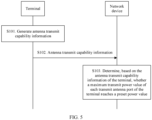
- FIG. 5 shows a power indication method according to an embodiment of this application. The method includes the following steps.
- a terminal generates antenna transmit capability information.
- the antenna transmit capability information is used to indicate a maximum transmit power value of each transmit antenna port of the terminal.
- the antenna transmit capability information is used to indicate whether a maximum transmit power value of each transmit antenna port of the terminal reaches a preset power value.
- the preset power value may be predefined, or may be determined based on a power class of the terminal.
- the preset power value is a maximum transmit power value corresponding to the power class reported by the terminal.
- the terminal may report the preset power value to a network device, where the preset power value is less than or equal to the maximum transmit power value corresponding to the power class reported by the terminal, so that the network device learns of the preset power value.
- a maximum transmit power value of a transmit antenna port is a maximum transmit power value of a PA corresponding to the transmit antenna port.
- Each PA is corresponding to one transmit chain (Tx chain)/transmit channel and a radio frequency (radio frequency, RF).
- Each transmit chain generates a respective transmit signal and amplifies power of the transmit signal by using the PA.
- the antenna transmit capability information includes at least one of the following information:
- the antenna configuration type is used to indicate a quantity of transmit antenna groups configured for the terminal, a quantity of transmit antenna ports included in each transmit antenna group, and a maximum transmit power value of each transmit antenna port in each transmit antenna group.
- two transmit antenna groups are configured for a terminal of antenna configuration type 6, where a quantity of transmit antenna ports included in a transmit antenna group 1 is 2, a maximum transmit power value of one transmit antenna port is 23 dBm, and a maximum transmit power value of the other transmit antenna port is 26 dBm; and a quantity of transmit antenna ports included in a transmit antenna group 2 is 2, a maximum transmit power value of one transmit antenna port is 20 dBm, and a maximum transmit power value of the other transmit antenna port is 23 dBm.
- Quantity of transmit antenna ports configured for the terminal and quantity of transmit antenna ports whose maximum transmit power values reach the preset power value For example, it is assumed that the preset power value is 23 dBm, and four transmit antenna ports are configured for the terminal, which are respectively a port 1, a port 2, a port 3, and a port 4.
- a maximum transmit power value of the port 1 is 20 dBm
- a maximum transmit power value of the port 2 is 23 dBm
- a maximum transmit power value of the port 3 is 20 dBm
- a maximum transmit power value of the port 4 is 26 dBm.
- the quantity that is of transmit antenna ports configured for the terminal and that is included in the antenna transmit capability information reported by the terminal is 4, and the quantity of transmit antenna ports whose maximum transmit power values reach the preset power value is 2.
- the antenna transmit capability information includes a quantity of transmit antenna ports in each transmit antenna group and a quantity of transmit antenna ports whose maximum transmit power values reach the preset power value, in each transmit antenna group.
- the transmit antenna port is represented by using SRS port information.
- the transmit antenna port is represented by using SRS port information in combination with group information of the transmit antenna group.
- the group information may be a group number, a group identifier, or a group index.
- the group information may further include another parameter related to the transmit antenna group.
- the following describes how the network device and the terminal determine information about a transmit antenna group to which a transmit antenna port belongs.
- the terminal may explicitly indicate, in the antenna transmit capability information, group information of a transmit antenna group to which each transmit antenna port belongs.
- the antenna transmit capability information includes group information of a transmit antenna group to which each transmit antenna port belongs and a maximum transmit power value of each transmit antenna port.
- the antenna transmit capability information includes group information of a transmit antenna group to which each transmit antenna port belongs and power indication information of each transmit antenna port.
- the terminal may alternatively implicitly indicate, in the antenna transmit capability information, SRS port information of each transmit antenna port and group information of a transmit antenna group to which each transmit antenna port belongs.
- the antenna transmit capability information includes a maximum transmit power value of each transmit antenna port, a position (or an arrangement order), of the maximum transmit power value of the transmit antenna port, in the antenna transmit capability information may be used to indicate group information of a transmit antenna group to which the transmit antenna port belongs.
- the antenna transmit capability information includes power indication information of each transmit antenna port, a position (or an arrangement order), of the power indication information of the transmit antenna port, in the antenna transmit capability information may be used to indicate group information of a transmit antenna group to which the transmit antenna port belongs.
- the following describes how the network device and the terminal determine the SRS port information of the transmit antenna port in combination with the antenna transmit capability information.
- the terminal pre-defines SRS port information of each transmit antenna port, and the terminal notifies the network device of the SRS port information by using the antenna transmit capability information.
- the terminal may explicitly indicate, in the antenna transmit capability information, the SRS port information of each transmit antenna port.
- the antenna transmit capability information includes the SRS port information and a maximum transmit power value of each transmit antenna port.
- the antenna transmit capability information includes the SRS port information and power indication information of each transmit antenna port.
- the terminal may alternatively implicitly indicate, in the antenna transmit capability information, the SRS port information of each transmit antenna port.
- the antenna transmit capability information includes the maximum transmit power value of each transmit antenna port, a position, of the maximum transmit power value of the transmit antenna port, in the antenna transmit capability information may be used to indicate the SRS port information of the transmit antenna port.
- the antenna transmit capability information includes the power indication information of each transmit antenna port, a position, of the power indication information of the transmit antenna port, in the antenna transmit capability information may be used to indicate the SRS port information of the transmit antenna port.
- the SRS port information of each transmit antenna port is determined between the terminal and the network device according to a preset rule.
- the preset rule is specified in a standard, or is delivered by the network device to the terminal.
- the preset rule is as follows: For each transmit antenna group, SRS port information corresponding to each transmit antenna port in the transmit antenna group is determined based on a ranking of a maximum transmit power value of each transmit antenna port in the transmit antenna group.
- the antenna transmit capability information includes four maximum transmit power values, which are respectively 20 dBm, 20 dBm, 23 dBm, and 26 dBm.
- an SRS port number (in this example, the SRS port information is the SRS port number) corresponding to a transmit antenna port whose maximum transmit power value is 26 dBm is 0, and an SRS port number corresponding to a transmit antenna port whose maximum transmit power value is 23 dBm is 1. It is set that an SRS port number corresponding to a transmit antenna port whose maximum transmit power value is 20 dBm is 2, and an SRS port number corresponding to the other transmit antenna port whose maximum transmit power value is 20 dBm is 3.
- the maximum transmit power value of the SRS port 0 is 23 dBm
- the maximum transmit power value of the SRS port 1 is 23 dBm
- the maximum transmit power values of both the SRS port 2 and the SRS port 3 are 20 dBm.
- the preset rule is as follows: For each antenna transmit group, a transmit antenna port whose maximum transmit power value reaches the preset power value corresponds to first SRS port information, and a transmit antenna port whose maximum transmit power value does not reach the preset power value corresponds to second SRS port information.
- a quantity of first SRS port information is a quantity of transmit antenna ports whose maximum transmit power values reach the preset power value and included in the transmit antenna group
- a quantity of second SRS port information is equal to a quantity of transmit antenna ports included in the transmit antenna group minus the quantity of transmit antenna ports whose maximum transmit power values reach the preset power value and included in the transmit antenna group.
- a value set of the first SRS port information and a value set of the second SRS port information may be preset, or may be determined by the network device and the terminal through negotiation. This is not limited in this embodiment of this application. It may be understood that the network device may obtain, from the antenna transmit capability information, the quantity of transmit antenna ports included in each transmit antenna group and the quantity of transmit antenna ports whose maximum transmit power values reach the preset power value.
- a quantity of transmit antenna ports included in the transmit antenna group is a quantity of transmit antenna ports configured for the terminal.
- the quantity of transmit antenna ports included in the transmit antenna group is 4, a quantity of transmit antenna ports whose maximum transmit power values reach the preset power value is 2, a value set of a first SRS port number (in this example, the SRS port information is the SRS port number) is ⁇ 0, 1 ⁇ , and a value set of a second SRS port number is ⁇ 2, 3 ⁇ .
- an SRS port number corresponding to one transmit antenna port whose maximum transmit power value reaches the preset power value is 0, an SRS port number corresponding to the other transmit antenna port whose maximum transmit power value reaches the preset power value is 1, an SRS port number corresponding to one transmit antenna port whose maximum transmit power value does not reach the preset power value is 2, and an SRS port number corresponding to the other transmit antenna port whose maximum transmit power value does not reach the preset power value is 3.
- the maximum transmit power value of the SRS port 0 reaches the preset power value
- the maximum transmit power value of the SRS port 1 reaches the preset power value
- the maximum transmit power value of the SRS port 2 does not reach the preset power value
- the maximum transmit power value of the SRS port 2 does not reach the preset power value.
- the quantity of transmit antenna ports included in the transmit antenna group is 4, a quantity of transmit antenna ports whose maximum transmit power values reach the preset power value is 2, a value set of a first SRS port number (in this example, the SRS port information is the SRS port number) is ⁇ 0, 3 ⁇ , and a value set of a second SRS port number is ⁇ 1, 2 ⁇ .
- an SRS port number corresponding to one transmit antenna port whose maximum transmit power value reaches the preset power value is 0, an SRS port number corresponding to the other transmit antenna port whose maximum transmit power value reaches the preset power value is 3, an SRS port number corresponding to one transmit antenna port whose maximum transmit power value does not reach the preset power value is 1, and an SRS port number corresponding to the other transmit antenna port whose maximum transmit power value does not reach the preset power value is 2.
- the maximum transmit power value of the SRS port 0 reaches the preset power value
- the maximum transmit power value of the SRS port 3 reaches the preset power value
- the maximum transmit power value of the SRS port 1 does not reach the preset power value
- the maximum transmit power value of the SRS port 2 does not reach the preset power value.
- the terminal sends the antenna transmit capability information to the network device, so that the network device receives the antenna transmit capability information.
- the terminal sends the antenna transmit capability information to the network device by using non-access stratum (non-access stratum, NAS) signaling.
- non-access stratum non-access stratum, NAS
- the terminal may actively send the antenna transmit capability information to the network device.
- the terminal sends the antenna transmit capability information to the network device.
- the network device determines, based on the antenna transmit capability information of the terminal, whether the maximum transmit power value of each transmit antenna port of the terminal reaches the preset power value.
- the antenna transmit capability information may indicate whether the maximum transmit power value of each transmit antenna port reaches the preset power value or indicate the maximum transmit power value of each transmit antenna port. Then, the network device may directly determine, based on the antenna transmit capability information, whether the maximum transmit power value reaches the preset power value; or first determine the maximum transmit power value of each transmit antenna port of the terminal based on the antenna transmit capability information, and then determine, based on the learned maximum transmit power value of each transmit antenna port, whether the maximum transmit power value reaches the preset power value.
- the network device measures each SRS port in the SRS resource; considers a factor, namely, a maximum transmit power value that can be used by each SRS port in uplink transmission, and performs compensation calculation on a reference signal sent by each SRS port to estimate a channel state of each SRS port, for example, a signal to interference plus noise ratio (signal to interference plus noise ratio, SINR), a signal-to-noise ratio (signal-noise ratio, SNR), reference signal received power (reference signal receiving power, RSRP), reference signal received quality (reference signal receiving quality, RSRQ); and then selects one or more SRS ports corresponding to an optimal channel state as an SRS port used for uplink transmission, and indicates the SRS port to the terminal by using a TPMI, so that the terminal sends uplink data by using the SRS port indicated by the TPMI.
- SINR signal to interference plus noise ratio
- SINR signal-to-noise ratio
- SNR reference signal received power
- RSRP reference signal received quality
- each SRS resource is corresponding to one transmit antenna group.
- the network device obtains a channel state of each transmit antenna group after measuring an SRS sent by the transmit antenna group on a corresponding SRS resource, so as to determine a transmit antenna group corresponding to an optimal channel state; and indicates, by using an SRI, the terminal to send uplink data by using the transmit antenna group. Further, based on a transmit antenna group corresponding to a selected SRS resource, the network device further selects an antenna port in the SRS resource.
- a selection manner is as follows: The network device measures each SRS port in the SRS resource; considers a factor, namely, a maximum transmit power value that can be used by each SRS port in uplink transmission, and performs compensation calculation on a reference signal sent by each SRS port to estimate a channel state of each SRS port; and then selects one or more SRS ports corresponding to an optimal channel state as an SRS port used for uplink transmission, and indicates the SRS port to the terminal by using an TPMI, so that the terminal sends uplink data by using the SRS port indicated by the TPMI.
- the network device learns whether the maximum transmit power value of each transmit antenna port of the terminal reaches the preset power value, when performing PUSCH scheduling, the network device comprehensively considers power of each transmit antenna port of the terminal, so that the network device indicates the terminal to perform uplink transmission by using a proper transmit antenna port, thereby ensuring system transmission performance.
- the network elements such as the network device and the terminal, include a corresponding hardware structure and/or software module that is used to perform each function.
- the network elements such as the network device and the terminal, include a corresponding hardware structure and/or software module that is used to perform each function.
- this application may be implemented by hardware or a combination of hardware and computer software. Whether a function is performed by hardware or hardware driven by computer software depends on particular applications and design constraints of the technical solutions. A person skilled in the art may use different methods to implement the described functions for each particular application, but it should not be considered that the implementation goes beyond the scope of this application.
- the network device and the terminal may be divided into function modules based on the foregoing method examples.
- each function module may be obtained through division based on each corresponding function, or two or more functions may be integrated into one processing module.
- the integrated module may be implemented in a form of hardware, or may be implemented in a form of a software functional module.
- division into modules is an example, and is merely a logical function division. In actual implementation, another division manner may be used. The following provides descriptions by using an example in which each function module is obtained through division based on a corresponding function.
- FIG. 6 is a schematic structural diagram of a terminal according to an embodiment of this application.
- the terminal includes a processing module 601 and a communications module 602.
- the processing module 601 is configured to support the terminal in performing step S101 in FIG. 5 and/or is used in another process used in the technical solution described in this specification.
- the communications module 602 is configured to support the terminal in performing step S102 in FIG. 5 and/or is used in another process used in the technical solution described in this specification. All related content of the steps in the foregoing method embodiments may be cited in function descriptions of corresponding function modules, and details are not described herein again.
- the communications module 602 in FIG. 6 may be implemented by the transceiver 303 in FIG. 4
- the processing module 601 in FIG. 6 may be implemented by the processor 301 in FIG. 4 . This is not limited in this embodiment of this application.
- An embodiment of this application further provides a computer-readable storage medium, where the computer-readable storage medium stores a computer instruction.
- the terminal When the computer-readable storage medium runs on the terminal shown in FIG. 4 , the terminal performs the power indication method shown in FIG. 5 .
- the computer instructions may be stored in a computer-readable storage medium or may be transmitted from a computer-readable storage medium to another computer-readable storage medium.
- the computer instructions may be transmitted from a website, computer, server, or data center to another website, computer, server, or data center in a wired (for example, a coaxial cable, an optical fiber, or a digital subscriber line (digital subscriber line, DSL)) or wireless (for example, infrared, radio, or microwave) manner.
- a wired for example, a coaxial cable, an optical fiber, or a digital subscriber line (digital subscriber line, DSL)
- wireless for example, infrared, radio, or microwave
- the computer-readable storage medium may be any usable medium accessible by a computer, or a data storage device, such as a server or a data center, integrating one or more usable media.
- the usable medium may be a magnetic medium (for example, a floppy disk, a hard disk, or a magnetic tape), an optical medium, a semiconductor medium (for example, a solid-state drive (solid state disk, SSD)), or the like.
- An embodiment of this application further provides a chip system, and the chip system includes a processor, configured to support a terminal in implementing the power indication method shown in FIG. 5 .
- the chip system further includes a memory.
- the memory is configured to store a program instruction and data that are necessary for the terminal. Certainly, the memory may not be in the chip system.
- the chip system may include a chip, or may include a chip and another discrete device. This is not specifically limited in this embodiment of this application.
- An embodiment of this application further provides a computer program product that includes a computer instruction.
- the computer program product runs on the terminal shown in FIG. 4
- the computer can perform the power indication method shown in FIG. 5 .
- the terminal, the computer storage medium, the chip system, and the computer program product provided in the foregoing embodiments of this application are all used to perform the foregoing power indication method. Therefore, for their beneficial effects, refer to beneficial effects corresponding to the foregoing method. Details are not described herein again.
- FIG. 7 is a schematic structural diagram of a network device according to an embodiment of this application.
- the network device includes a communications module 701 and a processing module 702.
- the communications module 701 is configured to support the network device in performing step S102 in FIG. 5 , and/or is used in another process of the technical solution described in this specification.
- the processing module 702 is configured to support the network device in performing step S103 in FIG. 5 , and/or is used in another process of the technical solution described in this specification. All related content of the steps in the foregoing method embodiments may be cited in function descriptions of corresponding function modules, and details are not described herein again.
- the communications module 701 in FIG. 7 may be implemented by the transceiver 203 in FIG. 4
- the processing module 702 in FIG. 7 may be implemented by the processor 201 in FIG. 4 . This is not limited in this embodiment of this application.
- An embodiment of this application further provides a computer-readable storage medium, where the computer-readable storage medium stores an instruction.
- the computer-readable storage medium runs on the network device shown in FIG. 4
- the network device performs the power indication method shown in FIG. 5 .
- An embodiment of this application further provides a chip system, and the chip system includes a processor, configured to support a network device in implementing the power indication method shown in FIG. 5 .
- the chip system further includes a memory.
- the memory is configured to store a program instruction and data that are necessary for the terminal. Certainly, the memory may not be in the chip system.
- the chip system may include a chip, or may include a chip and another discrete device. This is not specifically limited in this embodiment of this application.
- An embodiment of this application further provides a computer program product that includes a computer instruction.
- the computer program product runs on the network device shown in FIG. 4
- the computer can perform the power indication method shown in FIG. 5 .
- the network device, the computer storage medium, the chip system, and the computer program product provided in the foregoing embodiments of this application are all used to perform the foregoing power indication method. Therefore, for their beneficial effects, refer to beneficial effects corresponding to the foregoing method. Details are not described herein again.
Landscapes
- Engineering & Computer Science (AREA)
- Signal Processing (AREA)
- Computer Networks & Wireless Communication (AREA)
- Databases & Information Systems (AREA)
- Physics & Mathematics (AREA)
- Electromagnetism (AREA)
- Mathematical Physics (AREA)
- Mobile Radio Communication Systems (AREA)
Applications Claiming Priority (3)
| Application Number | Priority Date | Filing Date | Title |
|---|---|---|---|
| CN201811152760.9A CN110971317B (zh) | 2018-09-29 | 2018-09-29 | 功率指示方法及装置 |
| PCT/CN2019/109100 WO2020063974A1 (fr) | 2018-09-29 | 2019-09-29 | Procédé et dispositif d'indication de puissance |
| EP19868144.7A EP3852288B1 (fr) | 2018-09-29 | 2019-09-29 | Procédés et dispositifs d'indication de puissance |
Related Parent Applications (1)
| Application Number | Title | Priority Date | Filing Date |
|---|---|---|---|
| EP19868144.7A Division EP3852288B1 (fr) | 2018-09-29 | 2019-09-29 | Procédés et dispositifs d'indication de puissance |
Publications (2)
| Publication Number | Publication Date |
|---|---|
| EP4465546A2 true EP4465546A2 (fr) | 2024-11-20 |
| EP4465546A3 EP4465546A3 (fr) | 2025-01-22 |
Family
ID=69949539
Family Applications (2)
| Application Number | Title | Priority Date | Filing Date |
|---|---|---|---|
| EP24186877.7A Pending EP4465546A3 (fr) | 2018-09-29 | 2019-09-29 | Procédés et appareil d'indication de puissance |
| EP19868144.7A Active EP3852288B1 (fr) | 2018-09-29 | 2019-09-29 | Procédés et dispositifs d'indication de puissance |
Family Applications After (1)
| Application Number | Title | Priority Date | Filing Date |
|---|---|---|---|
| EP19868144.7A Active EP3852288B1 (fr) | 2018-09-29 | 2019-09-29 | Procédés et dispositifs d'indication de puissance |
Country Status (5)
| Country | Link |
|---|---|
| US (2) | US11997754B2 (fr) |
| EP (2) | EP4465546A3 (fr) |
| CN (2) | CN113965924A (fr) |
| ES (1) | ES2987250T3 (fr) |
| WO (1) | WO2020063974A1 (fr) |
Families Citing this family (23)
| Publication number | Priority date | Publication date | Assignee | Title |
|---|---|---|---|---|
| CN110535499B (zh) * | 2019-01-11 | 2024-03-01 | 中兴通讯股份有限公司 | 一种功率控制的实现方法、装置和通信节点 |
| CN113632393B (zh) * | 2019-03-29 | 2023-07-14 | 中兴通讯股份有限公司 | 使用群组标识进行配置的系统和方法以及计算机可读介质 |
| US11516755B2 (en) * | 2019-08-16 | 2022-11-29 | Qualcomm Incorporated | Signaling and configuration of maximum transmit power using virtual ports |
| US20230008524A1 (en) * | 2019-12-12 | 2023-01-12 | Ntt Docomo, Inc. | Terminal and radio communication method |
| CN114126023B (zh) * | 2020-08-31 | 2024-03-26 | 华为技术有限公司 | 一种功率配置方法及装置 |
| US12016042B2 (en) * | 2020-12-08 | 2024-06-18 | T-Mobile Usa, Inc. | Dynamic switching between uplink waveforms |
| CN114916052B (zh) * | 2021-02-08 | 2026-01-09 | 维沃移动通信有限公司 | 发射链路的处理方法、装置及终端 |
| CN115150817B (zh) * | 2021-03-31 | 2023-07-04 | 中国电信股份有限公司 | 多天线相干性能力上报方法、终端、基站以及存储介质 |
| CN115499906B (zh) * | 2021-06-19 | 2026-04-17 | 华为技术有限公司 | 一种最大输出功率的确定方法和装置 |
| WO2023065158A1 (fr) * | 2021-10-20 | 2023-04-27 | Oppo广东移动通信有限公司 | Procédé de communication sans fil, dispositif terminal et dispositif de réseau |
| CN116095802B (zh) * | 2021-11-05 | 2026-04-07 | 大唐移动通信设备有限公司 | Srs传输功率确定方法、装置及存储介质 |
| CN118435666A (zh) * | 2022-01-06 | 2024-08-02 | Oppo广东移动通信有限公司 | 通信方法、终端设备及网络设备 |
| KR20230112427A (ko) * | 2022-01-20 | 2023-07-27 | 삼성전자주식회사 | 무선 통신 시스템에서 상향링크 데이터 채널 전송을 위한 방법 및 장치 |
| CN116761241A (zh) * | 2022-03-03 | 2023-09-15 | 华为技术有限公司 | 一种通信方法及装置 |
| WO2023209599A1 (fr) * | 2022-04-26 | 2023-11-02 | Telefonaktiebolaget Lm Ericsson (Publ) | Procédés et nœuds pour rapporter des groupes d'antennes d'ue |
| US20260046783A1 (en) * | 2022-08-11 | 2026-02-12 | Beijing Xiaomi Mobile Software Co., Ltd. | Method and apparatus for sending uplink transmission power configuration, method and apparatus for receiving uplink transmission power configuration, and system |
| CN115361732A (zh) * | 2022-08-15 | 2022-11-18 | Oppo广东移动通信有限公司 | 功率调整方法、装置、终端、存储介质和计算机程序产品 |
| CN120548724A (zh) * | 2023-01-19 | 2025-08-26 | Oppo广东移动通信有限公司 | 无线通信的方法、终端设备及网络设备 |
| CN117136525A (zh) * | 2023-07-18 | 2023-11-28 | 北京小米移动软件有限公司 | 传输信息的方法、终端、网络设备、通信系统及存储介质 |
| WO2025022500A1 (fr) * | 2023-07-21 | 2025-01-30 | 株式会社Nttドコモ | Station de base et procédé de communication sans fil |
| KR20260009688A (ko) * | 2024-07-11 | 2026-01-20 | 삼성전자주식회사 | 무선 통신 시스템에서 상향링크 전송 전력 결정 방법 및 장치 |
| GB2642527A (en) * | 2024-07-12 | 2026-01-14 | Nokia Technologies Oy | A user equipment and network node |
| GB2642526A (en) * | 2024-07-12 | 2026-01-14 | Nokia Technologies Oy | A user equipment and network node |
Family Cites Families (29)
| Publication number | Priority date | Publication date | Assignee | Title |
|---|---|---|---|---|
| WO2009157169A1 (fr) * | 2008-06-23 | 2009-12-30 | パナソニック株式会社 | Procédé de compte rendu de marge de puissance et dispositif de station mobile |
| US8724488B2 (en) * | 2009-03-17 | 2014-05-13 | Interdigital Patent Holdings, Inc. | Method and apparatus for power control of sounding reference signal (SRS) transmission |
| MY161646A (en) * | 2009-10-02 | 2017-04-28 | Interdigital Patent Holdings Inc | Power control for devices having multiple antennas |
| CN105306187A (zh) * | 2009-11-19 | 2016-02-03 | 交互数字专利控股公司 | Wtru及在其中实施的用于处理载波聚合的方法 |
| ES2588978T3 (es) * | 2010-04-02 | 2016-11-08 | Interdigital Patent Holdings, Inc. | Configuración y transmisión de señales de sondeo de referencia de enlace ascendente |
| US9264954B2 (en) * | 2010-04-28 | 2016-02-16 | Qualcomm Incorporated | Neighbor relation information management |
| CN102300303A (zh) * | 2010-06-24 | 2011-12-28 | 夏普株式会社 | 上行多输入多输出信道的功率控制方法 |
| JP5270648B2 (ja) * | 2010-12-08 | 2013-08-21 | 株式会社日立製作所 | 分散アンテナシステム、基地局装置、アンテナ選択制御方法 |
| JP5859982B2 (ja) * | 2011-01-07 | 2016-02-16 | パナソニック インテレクチュアル プロパティ コーポレーション オブアメリカPanasonic Intellectual Property Corporation of America | 無線通信端末装置及び電力制御方法 |
| JP5372984B2 (ja) * | 2011-02-22 | 2013-12-18 | 株式会社日立製作所 | 分散アンテナシステム、通信制御方法、基地局装置 |
| CN102348269B (zh) * | 2011-09-27 | 2015-01-28 | 电信科学技术研究院 | 一种上行功率控制的方法和设备 |
| CN103384161B (zh) * | 2012-05-02 | 2018-02-06 | 华为技术有限公司 | Mimo无线通信系统、传输方法和装置 |
| US9497012B2 (en) * | 2012-09-26 | 2016-11-15 | Lg Electronics Inc. | Method and apparatus for receiving ACK/NACK in wireless communication system |
| JP2016500951A (ja) * | 2012-10-10 | 2016-01-14 | テレフオンアクチーボラゲット エル エム エリクソン(パブル) | 複合セルにおける位置決めの方法及びノード |
| CN103905104B (zh) * | 2012-12-28 | 2017-12-19 | 中兴通讯股份有限公司 | 一种根据探测参考信号的多天线发送方法及终端及基站 |
| WO2014201638A1 (fr) * | 2013-06-19 | 2014-12-24 | 华为技术有限公司 | Procédé et dispositif de mesure de qualité de communication |
| WO2016085092A1 (fr) * | 2014-11-28 | 2016-06-02 | Samsung Electronics Co., Ltd. | Procédé et système pour commander la transmission de mots de code au cours d'un transfert intercellulaire dans un réseau sans fil |
| CN107484251B (zh) * | 2016-06-08 | 2021-05-25 | 中国移动通信有限公司研究院 | 终端能力信息的上报方法、获取方法、终端及网络侧设备 |
| WO2018028393A1 (fr) * | 2016-08-12 | 2018-02-15 | 中兴通讯股份有限公司 | Procédé et appareil d'affectation de ressources sans fil |
| US10476650B2 (en) * | 2016-08-19 | 2019-11-12 | Qualcomm Incorporated | Control channel with flexible numerology |
| CN108023623B (zh) * | 2016-11-04 | 2022-05-27 | 维沃移动通信有限公司 | 一种终端信息上报、获取方法、终端及基站 |
| CN108271175B (zh) * | 2017-01-03 | 2023-06-02 | 华为技术有限公司 | 功率控制方法和通信设备 |
| EP3479647B1 (fr) * | 2017-05-05 | 2020-12-02 | Samsung Electronics Co., Ltd. | Procédé d'établissement d'une interface fronthaul et station de base |
| WO2018204816A1 (fr) * | 2017-05-05 | 2018-11-08 | Intel IP Corporation | Procédés et agencements pour signaler des véhicules aériens |
| CN115038154B (zh) * | 2017-06-16 | 2025-08-15 | 中兴通讯股份有限公司 | 发送功率的确定方法及装置、终端 |
| US10834625B2 (en) * | 2017-08-10 | 2020-11-10 | Qualcomm Incorporated | Carrier aggregation capability signaling |
| WO2019031190A1 (fr) * | 2017-08-10 | 2019-02-14 | ソニー株式会社 | Dispositif de communication, procédé de commande de communication, et programme informatique |
| CN109194453B (zh) * | 2017-11-17 | 2019-11-15 | 华为技术有限公司 | 相位跟踪参考信号的发送方法及装置 |
| CN108092755B (zh) * | 2017-12-26 | 2021-05-14 | Oppo广东移动通信有限公司 | 参数调整方法及装置 |
-
2018
- 2018-09-29 CN CN202111096172.XA patent/CN113965924A/zh active Pending
- 2018-09-29 CN CN201811152760.9A patent/CN110971317B/zh active Active
-
2019
- 2019-09-29 WO PCT/CN2019/109100 patent/WO2020063974A1/fr not_active Ceased
- 2019-09-29 ES ES19868144T patent/ES2987250T3/es active Active
- 2019-09-29 EP EP24186877.7A patent/EP4465546A3/fr active Pending
- 2019-09-29 EP EP19868144.7A patent/EP3852288B1/fr active Active
-
2021
- 2021-03-29 US US17/215,561 patent/US11997754B2/en active Active
-
2024
- 2024-04-24 US US18/644,756 patent/US12302454B2/en active Active
Also Published As
| Publication number | Publication date |
|---|---|
| CN110971317B (zh) | 2021-09-21 |
| US20240298168A1 (en) | 2024-09-05 |
| CN113965924A (zh) | 2022-01-21 |
| US20210219129A1 (en) | 2021-07-15 |
| EP4465546A3 (fr) | 2025-01-22 |
| EP3852288A1 (fr) | 2021-07-21 |
| US12302454B2 (en) | 2025-05-13 |
| CN110971317A (zh) | 2020-04-07 |
| EP3852288A4 (fr) | 2021-12-01 |
| EP3852288B1 (fr) | 2024-07-31 |
| ES2987250T3 (es) | 2024-11-14 |
| WO2020063974A1 (fr) | 2020-04-02 |
| US11997754B2 (en) | 2024-05-28 |
Similar Documents
| Publication | Publication Date | Title |
|---|---|---|
| US12302454B2 (en) | Power indication method and apparatus | |
| US20240313843A1 (en) | Precoding matrix configuration method and apparatus | |
| US11038576B2 (en) | Phase tracking reference signal sending method and apparatus | |
| US11937191B2 (en) | Communications method and apparatus | |
| US20220132441A1 (en) | Communication method and communications apparatus | |
| US11394521B2 (en) | Resource allocation indication and receiving methods and devices | |
| EP4068878B1 (fr) | Procédé et appareil d'indication d'un nombre de transmissions répétées | |
| US12256378B2 (en) | Method and systems for multiple precoder indication for physical uplink shared channel communications | |
| CN114424469A (zh) | 一种干扰测量上报的方法和通信装置 | |
| EP3902180A1 (fr) | Appareil et procédé d'indication de quasi-co-emplacement | |
| US12438759B2 (en) | Codebook and non-codebook support for SRS with 6 ports | |
| US10992435B2 (en) | Information indication method, device, and system | |
| US12047133B2 (en) | Transmit precoding matrix design for 8 Tx coherent PUSCH operation | |
| WO2022213248A1 (fr) | Amélioration de transmissions de pucch |
Legal Events
| Date | Code | Title | Description |
|---|---|---|---|
| PUAI | Public reference made under article 153(3) epc to a published international application that has entered the european phase |
Free format text: ORIGINAL CODE: 0009012 |
|
| STAA | Information on the status of an ep patent application or granted ep patent |
Free format text: STATUS: THE APPLICATION HAS BEEN PUBLISHED |
|
| AC | Divisional application: reference to earlier application |
Ref document number: 3852288 Country of ref document: EP Kind code of ref document: P |
|
| AK | Designated contracting states |
Kind code of ref document: A2 Designated state(s): AL AT BE BG CH CY CZ DE DK EE ES FI FR GB GR HR HU IE IS IT LI LT LU LV MC MK MT NL NO PL PT RO RS SE SI SK SM TR |
|
| REG | Reference to a national code |
Ref country code: DE Ref legal event code: R079 Free format text: PREVIOUS MAIN CLASS: H04B0007045600 Ipc: H04W0052360000 |
|
| PUAL | Search report despatched |
Free format text: ORIGINAL CODE: 0009013 |
|
| AK | Designated contracting states |
Kind code of ref document: A3 Designated state(s): AL AT BE BG CH CY CZ DE DK EE ES FI FR GB GR HR HU IE IS IT LI LT LU LV MC MK MT NL NO PL PT RO RS SE SI SK SM TR |
|
| RIC1 | Information provided on ipc code assigned before grant |
Ipc: H04W 8/24 20090101ALN20241216BHEP Ipc: H04B 7/0404 20170101ALN20241216BHEP Ipc: H04B 17/10 20150101ALN20241216BHEP Ipc: H04B 7/0456 20170101ALI20241216BHEP Ipc: H04B 7/06 20060101ALI20241216BHEP Ipc: H04L 5/00 20060101ALI20241216BHEP Ipc: H04W 52/14 20090101ALI20241216BHEP Ipc: H04W 52/36 20090101AFI20241216BHEP |
|
| STAA | Information on the status of an ep patent application or granted ep patent |
Free format text: STATUS: REQUEST FOR EXAMINATION WAS MADE |
|
| 17P | Request for examination filed |
Effective date: 20250722 |