EP4470867A1 - Accumulateur de stationnement pour véhicule de téléphérique - Google Patents
Accumulateur de stationnement pour véhicule de téléphérique Download PDFInfo
- Publication number
- EP4470867A1 EP4470867A1 EP24178588.0A EP24178588A EP4470867A1 EP 4470867 A1 EP4470867 A1 EP 4470867A1 EP 24178588 A EP24178588 A EP 24178588A EP 4470867 A1 EP4470867 A1 EP 4470867A1
- Authority
- EP
- European Patent Office
- Prior art keywords
- parking
- cable car
- conveyor
- parking track
- longitudinal section
- Prior art date
- Legal status (The legal status is an assumption and is not a legal conclusion. Google has not performed a legal analysis and makes no representation as to the accuracy of the status listed.)
- Pending
Links
Images


Classifications
-
- B—PERFORMING OPERATIONS; TRANSPORTING
- B61—RAILWAYS
- B61B—RAILWAY SYSTEMS; EQUIPMENT THEREFOR NOT OTHERWISE PROVIDED FOR
- B61B1/00—General arrangement of stations, platforms, or sidings; Railway networks; Rail vehicle marshalling systems
-
- B—PERFORMING OPERATIONS; TRANSPORTING
- B61—RAILWAYS
- B61B—RAILWAY SYSTEMS; EQUIPMENT THEREFOR NOT OTHERWISE PROVIDED FOR
- B61B12/00—Component parts, details or accessories not provided for in groups B61B7/00 - B61B11/00
- B61B12/02—Suspension of the load; Guiding means, e.g. wheels; Attaching traction cables
- B61B12/022—Vehicle receiving and dispatching devices
- B61B12/024—Docking devices
-
- B—PERFORMING OPERATIONS; TRANSPORTING
- B61—RAILWAYS
- B61B—RAILWAY SYSTEMS; EQUIPMENT THEREFOR NOT OTHERWISE PROVIDED FOR
- B61B12/00—Component parts, details or accessories not provided for in groups B61B7/00 - B61B11/00
- B61B12/10—Cable traction drives
-
- B—PERFORMING OPERATIONS; TRANSPORTING
- B65—CONVEYING; PACKING; STORING; HANDLING THIN OR FILAMENTARY MATERIAL
- B65G—TRANSPORT OR STORAGE DEVICES, e.g. CONVEYORS FOR LOADING OR TIPPING, SHOP CONVEYOR SYSTEMS OR PNEUMATIC TUBE CONVEYORS
- B65G35/00—Mechanical conveyors not otherwise provided for
-
- B—PERFORMING OPERATIONS; TRANSPORTING
- B61—RAILWAYS
- B61B—RAILWAY SYSTEMS; EQUIPMENT THEREFOR NOT OTHERWISE PROVIDED FOR
- B61B10/00—Power and free systems
- B61B10/02—Power and free systems with suspended vehicles
-
- B—PERFORMING OPERATIONS; TRANSPORTING
- B61—RAILWAYS
- B61B—RAILWAY SYSTEMS; EQUIPMENT THEREFOR NOT OTHERWISE PROVIDED FOR
- B61B10/00—Power and free systems
- B61B10/02—Power and free systems with suspended vehicles
- B61B10/022—Vehicles; trolleys
-
- B—PERFORMING OPERATIONS; TRANSPORTING
- B61—RAILWAYS
- B61B—RAILWAY SYSTEMS; EQUIPMENT THEREFOR NOT OTHERWISE PROVIDED FOR
- B61B12/00—Component parts, details or accessories not provided for in groups B61B7/00 - B61B11/00
-
- B—PERFORMING OPERATIONS; TRANSPORTING
- B61—RAILWAYS
- B61B—RAILWAY SYSTEMS; EQUIPMENT THEREFOR NOT OTHERWISE PROVIDED FOR
- B61B12/00—Component parts, details or accessories not provided for in groups B61B7/00 - B61B11/00
- B61B12/02—Suspension of the load; Guiding means, e.g. wheels; Attaching traction cables
- B61B12/022—Vehicle receiving and dispatching devices
-
- B—PERFORMING OPERATIONS; TRANSPORTING
- B61—RAILWAYS
- B61B—RAILWAY SYSTEMS; EQUIPMENT THEREFOR NOT OTHERWISE PROVIDED FOR
- B61B12/00—Component parts, details or accessories not provided for in groups B61B7/00 - B61B11/00
- B61B12/10—Cable traction drives
- B61B12/105—Acceleration devices or deceleration devices other than braking devices
-
- B—PERFORMING OPERATIONS; TRANSPORTING
- B65—CONVEYING; PACKING; STORING; HANDLING THIN OR FILAMENTARY MATERIAL
- B65G—TRANSPORT OR STORAGE DEVICES, e.g. CONVEYORS FOR LOADING OR TIPPING, SHOP CONVEYOR SYSTEMS OR PNEUMATIC TUBE CONVEYORS
- B65G35/00—Mechanical conveyors not otherwise provided for
- B65G35/06—Mechanical conveyors not otherwise provided for comprising a load-carrier moving along a path, e.g. a closed path, and adapted to be engaged by any one of a series of traction elements spaced along the path
-
- B—PERFORMING OPERATIONS; TRANSPORTING
- B65—CONVEYING; PACKING; STORING; HANDLING THIN OR FILAMENTARY MATERIAL
- B65G—TRANSPORT OR STORAGE DEVICES, e.g. CONVEYORS FOR LOADING OR TIPPING, SHOP CONVEYOR SYSTEMS OR PNEUMATIC TUBE CONVEYORS
- B65G47/00—Article or material-handling devices associated with conveyors; Methods employing such devices
- B65G47/74—Feeding, transfer, or discharging devices of particular kinds or types
Definitions
- the present invention relates to a parking storage facility for cable car vehicles with a meandering parking track for accommodating cable car vehicles, wherein the parking track has at least a first parking track longitudinal section and a second parking track longitudinal section, which are arranged at a distance from one another, and the first and second parking track longitudinal sections are connected to one another via a first parking track curve section, wherein the cable car vehicles can be moved along the parking track in a conveying direction using a parking conveyor.
- the invention further relates to a method for storing a cable car vehicle in a parking storage facility.
- Circulating cable cars generally have a number of cable car stations, a number of cable car vehicles and a haulage cable for moving the cable car vehicles between the cable car stations.
- the haulage cable runs between the cable car stations, for example on cable pulleys in the cable car stations, with at least one cable pulley being driven.
- Circulating cable cars are also known in which the cable car vehicles are uncoupled from the haulage cable in a cable car station in order to be moved through the cable car station in the uncoupled state and independently of the haulage cable. Before leaving the cable car station, the cable car vehicles are accelerated back to the speed of the haulage cable and coupled to the haulage cable.
- at least one guide rail is provided within the cable car station, along which the cable car vehicles are guided through the cable car station when they are uncoupled from the conveyor cable.
- the cable car vehicles for example on the suspension, are usually equipped with rollers with which the cable car vehicles roll along the guide rail.
- a station conveyor is provided to convey the uncoupled cable car vehicles in a cable car station.
- the station conveyor can be designed as a known tire conveyor, in which driven tires arranged along the guide rail in the cable car station interact with a friction lining on the cable car vehicles.
- the friction lining can be arranged on the suspension of the cable car vehicle, for example.
- the station conveyor can also be designed differently, for example as a mechanical continuous conveyor with a traction device (for example a belt or chain) on which carriers are provided which interact with part of a cable car vehicle in order to move it at the speed of the traction device. All cable car vehicles on the traction device are thus moved at the same speed of the traction device.
- Such circulating cable cars with cable car vehicles that can be decoupled from the haulage cable often also have a parking storage area in which the cable car vehicles that have been decoupled from the haulage cable can be parked outside of the operating hours of the circulating cable car.
- a number of cable car vehicles can also be parked in the parking storage area during operation of the circulating cable car, for example during times when there is little demand for transport.
- Such a parking storage area is usually located inside or in the area of one of the cable car stations, for example on the same level as the operating area in which the boarding and/or alighting area for passengers is located or in a garage below the operating area.
- a parking conveyor is usually provided, which can include one or more conveyor devices.
- the parking conveyor is usually connected to the station conveyor in order to transfer cable car vehicles from the station conveyor to the parking conveyor, or vice versa. Switches can also be provided for this purpose in order to move cable car vehicles from the station conveyor to the parking conveyor, or vice versa.
- Examples of parking conveyors are EP 711 696 A1 or AT 392 766 B known.
- the movement of the cable car vehicles in the parking storage often takes place on so-called gradient tracks as a parking conveyor, or part of a parking conveyor.
- a gradient track is essentially designed in the same way as the guide rail of the cable car station, but has a certain fixed gradient.
- the movement of the cable car vehicles along the gradient track into the parking position takes place only by gravity due to the defined gradient, without an external drive.
- the gradient track can, for example, be connected to the guide rail of the cable car station via a switch, so that the cable car vehicles can be diverted from the guide rail to the gradient track for parking via the switch.
- the return transport of the cable car vehicles from the parking storage to the operating area can, for example, be carried out with a tire conveyor in a similar way to the drive of the cable car vehicles along the guide rail in the operating area of the cable car station.
- a gradient track has a number of disadvantages.
- a sloping track is susceptible to failure, because too little gradient of the sloping track and/or unevenness, foreign objects, dirt, ice, etc. on the sloping track or on the cable car vehicles can lead to an unintended movement of the cable car vehicle, such as an unwanted stop, a movement that is too slow or too fast, etc., or to the cable car vehicles blocking.
- parking tracks are often arranged parallel to each other, which are supplied via a feeder track that connects the parking tracks.
- An example of this is in WO 2010/082125 A1 or AT 392 766 B
- the disadvantage of such parking storage systems is that a switch is required for each parking track in order to divert a cable car vehicle from the feeder track to the parking track, or vice versa, which increases the effort.
- AT 392 766 B A continuous conveyor is provided on the feeder track as a parking conveyor and the cable car vehicles are moved on the parking tracks by self-propelled cable car vehicle supports.
- this design is very complex because there must be a cable car vehicle support with its own drive for each cable car vehicle.
- WO 2010/082125 A1 A tire conveyor is provided on the feeder track and a continuous conveyor on the parking track, whereby the continuous conveyor is driven by the movement of the cable car vehicle on the tire conveyor. To achieve this, the tire conveyor and the continuous conveyor overlap a little. However, such a parking conveyor is susceptible to malfunctions. Due to slippage errors in the tire conveyor and due to spacing errors of the cable car vehicle on the tire conveyor, the drive of the parking track's ascending conveyor can easily be interrupted.
- the parking track is designed in a meandering shape and the cable car vehicles are lined up one behind the other on the meandering parking track.
- the cable car vehicles on the parking track should of course be as close to each other as possible.
- the individual branches of the meandering parking track are also arranged as close to each other as possible.
- the meandering arrangement of the parking track requires curved connections with small radii between adjacent parallel branches of the parking track.
- cable car vehicles with large widths are often used to increase the transport capacity.
- the inventive design of the parking storage facility makes it possible to move cable car vehicles on the parking track longitudinal sections with a very small distance behind one another, which can save space.
- the cable car vehicles are accelerated at the transition to the parking track curved section in order to increase the distance.
- the cable car vehicles are decelerated again in order to reduce the distance again, so that the cable car vehicles can be moved on the following parking track longitudinal section with a small distance.
- a particularly smooth transition from the parking track curve section to a parking track longitudinal section can be achieved if at least one tire of the tire conveyor in the second overlap region, preferably in the region of the end or at the end of the second overlap region, is driven via a slip clutch and/or at least one tire of the tire conveyor in the first overlap region, preferably in the region of the beginning or at the beginning of the first overlap region, is driven via a slip clutch.
- the driver is U-shaped with two protruding legs, whereby an engagement area is formed between the legs in a driving position, in which a part of the cable car vehicle comes to rest during operation of the parking storage in order to bring the driver into engagement with the cable car vehicle. This enables easy engagement between the driver and the cable car vehicle.
- Fig.1 shows very schematically a cable car station 2 of a circulating cable car 1.
- the circulating cable car usually has a second cable car station, which is Fig.1 is not shown.
- a haulage cable 3 runs between the cable car stations 2, for example on cable pulleys 4 in the cable car stations 2, with at least one cable pulley 4 being driven by a cable car drive 8.
- Cable car vehicles 5, such as gondolas or chairs, are transported between the cable car stations 2 on the haulage cable 3.
- the cable car vehicles 5 are uncoupled from the haulage cable 3 in a known manner after entering the cable car station 2.
- the cable car vehicles 5 are coupled again to the haulage cable 3.
- Cable clamps 23 on the cable car vehicles 5 are used for uncoupling and coupling.
- at least one guide rail 6 is provided, along which the cable car vehicles 5 are guided in the cable car station 2.
- a station conveyor 7, for example a tire conveyor or a continuous conveyor, is provided for moving a cable car vehicle 5 decoupled from the conveyor cable 3 in the cable car station 2 along the guide rail 6.
- At least one guide roller 21, 22 is also arranged on the hanger 20, which cooperates with at least one guide rail 6 in the cable car station 2 in order to guide the cable car vehicle 5 in the cable car station 2 along the at least one guide rail 6.
- the station conveyor 7 is designed in this embodiment as a tire conveyor, in which a plurality of driven tires 27 are arranged in the cable car station 2 so as to be rotatable one behind the other in the conveying direction.
- the tires 27 interact with a friction lining 26 on the hanger 20 to move the cable car vehicle 5, which is uncoupled from the conveyor cable 3, through the cable car station 2 by the rotation of the tires 27 along the guide rail 6.
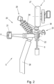
- a feeder track 32 can be provided, as in Fig.2 shown.
- the feeder track 32 is connected at one end to the station conveyor 7 via a station switch 33 and at the opposite end to the parking track 31 via a parking switch 34.
- a cable car vehicle 5 can be diverted from the station conveyor 7 to the feeder track 32 and further to the parking track 31.
- a cable car vehicle 5 can be diverted from the parking track 31 to the feeder track 32 and further to the station conveyor 7 via the parking switch 34.
- the parking track 31 could also be connected directly to the station conveyor 7 via the station switch 32, which would also eliminate the need for a parking switch 34.
- a parking conveyor 35 is provided, which is Fig.1 is only indicated for a short section in the direction of transport R, but of course extends along the entire part of the parking track 31 used by cable car vehicles 5.
- a second feeder track 32 is provided, which in turn is connected to the station conveyor 7 by a station switch 33 and to the parking track 31 by a parking switch 34.
- the second feeder track 32 could also be omitted if the parking track 31 is connected directly to the station conveyor 7 via the station switch 33.
- the use of two feeder tracks 32, or two station switches 33 connected to the parking track 31, has the advantage that loading and unloading can take place in different ways and the cable car vehicles 5 only have to be moved in one direction.
- the parking track 31 is connected to the station conveyor 7 in the cable car station 2, because the invention relates to the design of the parking storage 30, in particular to the design of the parking conveyor 35.
- the parking track 31 of the parking storage facility 30 has at least one first parking track longitudinal section 40 and at least one second parking track longitudinal section 41, which are arranged next to one another at a distance from one another transversely to the conveying direction R.
- the first parking track longitudinal section 40 and the second parking track longitudinal section 41 are connected to one another via a first parking track curved section 42.
- a parking track longitudinal section 40, 41 is an essentially straight section of the parking track 31.
- the first parking track longitudinal section 40 and the second parking track longitudinal section 41 are parallel to one another at least in sections.
- the first parking track curved section 42 can be designed in the shape of a circular arc, but can also have a different arc.
- more than two parking track longitudinal sections 40, 41, 43, 44 are provided next to one another and spaced apart from one another transversely to the conveying direction R, with two adjacent parking track longitudinal sections 40, 41, 43, 44 being alternately connected to one another at different ends of the parking track longitudinal sections 40, 41, 43, 44 via a parking track curve section 42 in order to create a continuous meandering parking track 31.
- the individual parking track curve sections 42 do not necessarily have to be designed the same, however.
- the two outer parking track longitudinal sections 40, 44 can be connected to one another via a further parking track curve section 45.
- the first parking track longitudinal section 40 is connected to a feeder track 32 or directly to the station conveyor 7 and that the last parking track longitudinal section 40 is connected to a further feeder track 32 or directly to the station conveyor 7.
- FIG.3 and 4 the parking conveyor 35 according to the invention of the parking storage 30 with a parking track 31 is described.
- a part of a first parking track longitudinal section 40 and a part of a second parking track longitudinal section 41 are shown, which are connected to one another by a first parking track curve section 42.
- a parking conveyor 35 is provided in the parking storage 30 to move a cable car vehicle 5 along the parking track 31.
- the parking conveyor 35 comprises a continuous conveyor 50 and a tire conveyor 51.
- the one continuous conveyor 50 comprises at least one traction means 52 ( Fig.3 ), which rotates in a conveying direction R at a predetermined continuous conveying speed vs during operation of the parking storage 30.
- a plurality of drivers 53 are arranged on the traction means 52, which are moved with the traction means 52 at the continuous conveying speed vs.
- a driver 53 acts with a part of the cable car vehicle 5, for example with the suspension rod 28 as in Fig.3 , together to move the cable car vehicle 5.
- the driver 53 can simply rest against a part of the cable car vehicle 5, or be otherwise connected to a part of the cable car vehicle 5.
- the continuous conveyor 50 is set up to move a cable car vehicle 5 in the conveying direction R with the drivers 53 at a continuous conveying speed vs along the longitudinal parking track sections 40, 41 during operation of the parking storage 30.
- the traction means 52 is arranged in a traction means housing 54 that is open on one side.
- the continuous conveyor 50 can also have a conveyor belt or a conveyor chain as traction means 52 that rotate on conveyor disks and on which drivers 53 are arranged.
- the continuous conveyor 50 in the version according to Fig.3 is arranged in the area of the first parking track longitudinal section 40 and in the area of the second parking track longitudinal section 40 in order to move a cable car vehicle 5 along these sections.
- the continuous conveyor 50 is also arranged in a meandering shape.
- a continuous conveyor 50 with separate traction means 52 could also be provided for the first parking track longitudinal section 40 and the second parking track longitudinal section 40, and also for further parking track longitudinal sections 43, 43.
- the continuous conveyor 50 would also be arranged in a meandering manner along the associated parking track longitudinal sections 40, 41, 43, 44.
- the continuous conveyor 50 could therefore run at the opposite end of the parking track longitudinal sections 40, 41 in the direction of another adjacent parking track longitudinal section 43 transverse to the conveying direction R, so that the traction means 52 of the Inclined conveyor 50 also moves a cable car vehicle 5 on this further parking track longitudinal section 43.
- the cable car vehicles 5 would be moved in the same direction, in the parking track longitudinal section 41 in between, in the opposite direction. This can be provided for any number of parking track longitudinal sections.
- the conveying directions R on two adjacent parking track longitudinal sections 40, 41 are opposite.
- This circumstance can be advantageously exploited by using a continuous conveyor 50 with a single traction means 52 for both, or even for more than two, parking track longitudinal sections 40, 41, as in the embodiment according to Fig.3
- the rotating traction means 52 of the continuous conveyor 50 then moves along the two, or more than two, parking track longitudinal sections 40, 41 alternately in opposite directions.
- the cable car vehicles 5 are thus moved on the two, or more than two, parking track longitudinal sections 40, 41 by the same traction means 52.
- a continuous conveyor 50 with separate traction means 52 with carriers 53 could also be used, with one traction means 52 being provided for each assigned parking track longitudinal section(s) 40, 41.
- the tire conveyor 51 of the parking conveyor 35 is provided in the area of the first parking track curve section 42 in order to move a cable car vehicle 5 along the parking track curve section 42.
- the tire conveyor 51 has a plurality of driven tires 57 arranged one behind the other in the conveying direction R.
- the tire conveyor 35 is set up to move a cable car vehicle 5 in the conveying direction R with a tire conveying speed v R along the first parking track curve section 42 when the parking storage facility 30 is in operation with the driven tires 57.
- the tires 57 interact to move the cable car vehicle 5, for example in a known manner with a friction lining 26 on the suspension 20 of the cable car vehicle 5, for example as in Fig.2 shown.
- the tires 57 may be driven individually, or driven in groups, or all driven together.
- a tire drive 58 for example an electric motor, possibly also with a gear, is provided, which drives a tire 57 of the tire conveyor 51.
- a double pulley 59 is arranged on each tire 57.
- Each double pulley 59 (except the last one) is connected to both adjacent tires 57 with a belt, such as a V-belt or toothed belt, with double pulley 59 (in Fig.3 not shown for reasons of clarity).
- the tire drive thus drives 58 all tires 57.
- By selecting the pulley diameters it is also easy to implement transmission or reduction ratios in the rotational speeds of the tires 57, and thus also different tire conveying speeds v R in the area of the tires 57 of the tire conveyor 51.
- each tire 57 is driven individually by a tire drive 58.
- the continuous conveyor 50 and the tire conveyor 51 overlap in a first overlap region 60 in the region of the transition from the first parking track longitudinal section 40 to the parking track curved section 42 and in a second overlap region 61 in the region of the transition from the parking track curved section 42 to the second parking track longitudinal section 41.
- Fig.5 The fundamental problem with a meandering parking track 31 is explained by Fig.5 explained.
- a longitudinal parking track section 40, 41 cable car vehicles 5 can be moved very closely spaced in the direction of transport R.
- the distance A in the direction of transport R between two adjacent cable car vehicles 5 can therefore be kept very small in order to be able to keep the construction area of the parking storage facility 30 small.
- the cable car vehicles 5 deflect in the curved parking track section 42, which would lead to a collision between two adjacent cable car vehicles 5 if the distance A was small, which must be prevented at all costs. Therefore, the distance A on the longitudinal parking track section 40 in front of the curved parking track section 42 had to be chosen to be large enough to prevent a collision despite the deflection.
- this inevitably leads to a larger construction area for the parking storage facility 30.
- the invention provides that during the transition from the first longitudinal parking track section 40 to the first curved parking track section 42, the tire conveying speed v R of the tire conveyor 51 increases in the first overlap region 60 in order to accelerate a cable car vehicle 5 with the tire conveyor 51 compared to the continuous conveying speed vs on the continuous conveyor 50 when the parking storage 30 is in operation.
- the tire conveying speed v R of the first tire 57 in the first overlap region 60 advantageously corresponds to the continuous conveying speed vs of the continuous conveyor 50 and increases with each subsequent tire 57 in the first overlap region 60.
- the engagement of the driver 63 on the cable car vehicle 5 is released, so that the cable car vehicle 5 is only driven by the tire conveyor 51, at least at the end of the first overlap region 60.
- the tire conveying speed v R of the tire conveyor 51 is reduced in the second overlap area 61 in order to decelerate a cable car vehicle 5 with the tire conveyor 51 during operation of the parking storage 30.
- the Tire conveying speed v R of the last tire 57 in the second overlap region 61 advantageously corresponds to the continuous conveying speed vs of the continuous conveyor 50.
- a driver 53 on the traction means 52 of the continuous conveyor 50 is brought into engagement with the cable car vehicle 5, so that the cable car vehicle 5 is only moved by the continuous conveyor 51, at least at the end of the second overlap region 61.
- the continuous conveyor 51 can be displaced at the beginning of the first overlap area 60 transversely to the conveying direction R and away from the cable car vehicle 5, as shown in Fig.3 shown, so that the driver 53 loses its engagement with the cable car vehicle 5 simply by the lateral displacement.
- the procedure can be exactly the opposite to that in Fig.3 shown.
- the continuous conveyor 51 is displaced at the end of the second overlap region 61 transversely to the conveying direction R and towards the cable car vehicle 5, so that a driver 53 on the traction means 52 comes into engagement with a part of the cable car vehicle 5.
- the distance A between two adjacent cable car vehicles 5 on the first parking track longitudinal section 40 is increased.
- the distance A can be increased such that a collision of the cable car vehicles 5 deflecting on the parking track curved section 42 is safely avoided.
- the acceleration in the first overlap area 60 can be realized, for example, by a suitable choice of the pulley diameters of the double pulleys 59 of the tires 57 in the area of the first overlap area 60, or by individually driven tires 57 in the first overlap area 60.
- the speed of the cable car vehicle 5 can be adjusted again to the continuous conveying speed vs, so that the cable car vehicle 5 can be moved as smoothly as possible.
- the distance A between two adjacent cable car vehicles 5 is reduced again, so that the cable car vehicles 5 on the second parking track longitudinal section 41 can again be moved with a close distance A.
- the deceleration in the second overlap area 61 can also be realized, for example, by a suitable choice of the pulley diameters of the double pulleys 59 of the tires 57 in the area of the second overlap area 61, or by individually driven tires 57 in the second overlap area 61.
- a constant tire conveying speed v R can be set along the parking track curve section 42 between the first overlap region 60 and the second overlap region 61.
- a number of tires 57 at the end of the second overlap area 61 can be provided with a slip clutch 49.
- the slip clutch 49 serves to ensure that from a moment at which the continuous conveyor 51 acts on the cable car vehicle 5, a tire 57, which also still interacts with the cable car vehicle 5, slips and no longer exerts any driving force on the cable car vehicle 5. This can reliably prevent two drives with different conveying speeds from acting on the cable car vehicle 5 at the same time.
- a number of tires 57 at the beginning of the first overlap area 60 can also be designed with such a slip clutch 49. This makes it possible in particular to realize a smooth operation of the parking conveyor 35 in both possible conveying directions.
- a number of tires 57 at the end of the second overlap area 61 could be regulated with regard to the realized tire conveying speed v R. For this, however, these tires 57 must be driven separately. This can also be used to achieve a smooth transition at the second overlap area 61 from the tire conveying speed v R on the parking track curve section 42 to the continuous conveying speed vs of the continuous conveyor 50 by regulating the rotational speed of these tires 57. This also applies analogously to tires 57 at the beginning of the first overlap area 60. A mixture would also be conceivable, i.e. slip clutches 49 on tires 57 in the second overlap area 61 and regulated tires in the first overlap area 60, or vice versa.
- a driver 53 is preferably U-shaped with two protruding legs 62, 63, whereby an engagement region 64 is formed between the legs 62, 63 in a driving position of the legs 62, 63, in which a part of the cable car vehicle 5, for example a part of the suspension or the means of transport, comes to rest during operation of the parking storage 30 in order to bring the driver 53 into engagement with the cable car vehicle 5.
- the driver 53 can, however, be designed in any other way to implement the engagement.
- a coupling could also be implemented which is coupled for engagement and disengaged for release.
- moving parts with their own drive can also be provided on the driver 53 and/or on the cable car vehicle 5.
- a roller 65 can also be rotatably mounted on a free axial end of at least one protruding leg 62, 63, as in Fig.4 shown.
- the roller 65 allows the engagement between the driver 53 and the cable car vehicle 5 and the release between the driver 53 and the cable car vehicle 5 to take place more smoothly because the roller 65 of a leg 62, 63 simply rolls off the corresponding part of the cable car vehicle.
- the engagement between the driver 53 and the cable car vehicle 5 can also be improved if at least one protruding leg 63 is arranged so as to be rotatably mounted on an axial end of the leg 63 opposite the axial free end, so that the leg 63 can be pivoted in particular in the direction of the engagement region 64 (in Fig.4 indicated by dashed lines).
- a spring element (not shown) can also be provided on the driver 53, which presses the pivotally mounted leg 63 into the driving position.
- the pivotally mounted leg 63 is preferably the rear leg of the driver 53 in the conveying direction R. Such a pivotally mounted leg 63 enables the engagement between the driver 53 and the cable car vehicle 5 to be established simply and safely.
- the spring element causes the leg 63 to move back into a driving position with the leg 63 protruding.
- the moving leg 63 can then rest against a part of the cable car vehicle 5 and thereby take the cable car vehicle 5 along in the conveying direction R.
- a parking storage facility 30 with more than two parking track longitudinal sections 40, 41, 43, 44, as in Fig.3 preferably two adjacent parking track longitudinal sections 40, 41, 43, 44 are each served by a continuous conveyor 51 with a traction means 52.
- a tire conveyor 51 is provided in each parking track curved section 42 between these parking track longitudinal sections 40.
- a tire conveyor 51 is also preferably provided on the further parking track curved section 45, if present.
- only a first parking track longitudinal section 40 and a second parking track longitudinal section 41 connected to it with a parking track curved section 42 are equipped with an inventive design of a parking conveyor 35 and other parking track longitudinal sections and parking track curved sections are equipped with a different design of a parking conveyor 35.
- the parking track 31 is preferably formed by at least one parking guide rail 36, which is similar to Fig.2 shown, interacts with at least one guide roller 21, 22 on the cable car vehicle 5 in order to guide the cable car vehicle 5 along the parking track 36.
- the components already provided for the operation of the circulating cable car 1 on the cable car vehicle 5 are thus also advantageously used for the parking storage 30.
Landscapes
- Engineering & Computer Science (AREA)
- Mechanical Engineering (AREA)
- Transportation (AREA)
- Automobile Manufacture Line, Endless Track Vehicle, Trailer (AREA)
- Intermediate Stations On Conveyors (AREA)
Applications Claiming Priority (1)
| Application Number | Priority Date | Filing Date | Title |
|---|---|---|---|
| ATA50427/2023A AT527273A1 (de) | 2023-05-31 | 2023-05-31 | Parkspeicher für Seilbahnfahrzeug |
Publications (1)
| Publication Number | Publication Date |
|---|---|
| EP4470867A1 true EP4470867A1 (fr) | 2024-12-04 |
Family
ID=91302588
Family Applications (1)
| Application Number | Title | Priority Date | Filing Date |
|---|---|---|---|
| EP24178588.0A Pending EP4470867A1 (fr) | 2023-05-31 | 2024-05-28 | Accumulateur de stationnement pour véhicule de téléphérique |
Country Status (4)
| Country | Link |
|---|---|
| US (1) | US20240400115A1 (fr) |
| EP (1) | EP4470867A1 (fr) |
| CN (1) | CN119059186A (fr) |
| AT (1) | AT527273A1 (fr) |
Citations (7)
| Publication number | Priority date | Publication date | Assignee | Title |
|---|---|---|---|---|
| US4785738A (en) * | 1986-05-06 | 1988-11-22 | Pomagalski S.A. | Detachable gondola lift or chair-lift |
| AT392766B (de) | 1989-02-16 | 1991-06-10 | Swoboda Seilbahnbau Gmbh | Anlage zum abstellen der fahrbetriebsmittel einer kuppelbaren umlaufseilbahn |
| EP0711696A1 (fr) | 1994-11-08 | 1996-05-15 | Garaventa Holding Ag | Garage pour les véhicules d'un téléphérique |
| JPH09150733A (ja) * | 1995-11-30 | 1997-06-10 | Kawaden Co Ltd | 索道における搬器入出庫システム |
| WO2010082125A1 (fr) | 2009-01-16 | 2010-07-22 | Rolic Invest Sarl | Entrepôt d'unités de transport pour systèmes de transport par câble et procédé d'actionnement dudit entrepôt |
| EP2551164A2 (fr) * | 2011-07-27 | 2013-01-30 | Bartholet Maschinenbau AG | Système de garage pour stationnement |
| EP2370300B1 (fr) * | 2008-11-28 | 2014-08-20 | Rolic International S.A R.L. | Entrepôt équipé de modules de transport d' un système aérien |
-
2023
- 2023-05-31 AT ATA50427/2023A patent/AT527273A1/de unknown
-
2024
- 2024-05-28 EP EP24178588.0A patent/EP4470867A1/fr active Pending
- 2024-05-29 US US18/676,951 patent/US20240400115A1/en active Pending
- 2024-05-30 CN CN202410688422.6A patent/CN119059186A/zh active Pending
Patent Citations (7)
| Publication number | Priority date | Publication date | Assignee | Title |
|---|---|---|---|---|
| US4785738A (en) * | 1986-05-06 | 1988-11-22 | Pomagalski S.A. | Detachable gondola lift or chair-lift |
| AT392766B (de) | 1989-02-16 | 1991-06-10 | Swoboda Seilbahnbau Gmbh | Anlage zum abstellen der fahrbetriebsmittel einer kuppelbaren umlaufseilbahn |
| EP0711696A1 (fr) | 1994-11-08 | 1996-05-15 | Garaventa Holding Ag | Garage pour les véhicules d'un téléphérique |
| JPH09150733A (ja) * | 1995-11-30 | 1997-06-10 | Kawaden Co Ltd | 索道における搬器入出庫システム |
| EP2370300B1 (fr) * | 2008-11-28 | 2014-08-20 | Rolic International S.A R.L. | Entrepôt équipé de modules de transport d' un système aérien |
| WO2010082125A1 (fr) | 2009-01-16 | 2010-07-22 | Rolic Invest Sarl | Entrepôt d'unités de transport pour systèmes de transport par câble et procédé d'actionnement dudit entrepôt |
| EP2551164A2 (fr) * | 2011-07-27 | 2013-01-30 | Bartholet Maschinenbau AG | Système de garage pour stationnement |
Also Published As
| Publication number | Publication date |
|---|---|
| CN119059186A (zh) | 2024-12-03 |
| US20240400115A1 (en) | 2024-12-05 |
| AT527273A1 (de) | 2024-12-15 |
Similar Documents
| Publication | Publication Date | Title |
|---|---|---|
| DE69514422T2 (de) | Seilbahnsystem von Typ Schiene und Zugkabel, insbesondere für öffentlichen Nahverkehr, bei dem die Fahrzeuge eine mobile Klemme zum Ankuppeln an das Zugkabel und zum Abkuppeln davon haben | |
| EP2455267B1 (fr) | Installation de transport de personnes et procédé de fonctionnement de cette installation | |
| WO2001083336A1 (fr) | Dispositif de transport et/ou de stockage pour marchandises en colis | |
| EP1925522B1 (fr) | Installation de transport à câble aérien dotée d'une station de stockage de véhicules | |
| DE2646828A1 (de) | Durchgehendes befoerderungssystem | |
| EP0773074A1 (fr) | Accumulateur de bandes horizontal | |
| EP4204271B1 (fr) | Dispositif de stationnement pour téléphérique | |
| EP0306771B1 (fr) | Dispositif de rails de garage pour les véhicules d'une installation de téléphérage en circuit fermé | |
| EP4470867A1 (fr) | Accumulateur de stationnement pour véhicule de téléphérique | |
| WO2019201797A1 (fr) | Installation de convoyage avec un chariot de convoyage | |
| AT527051B1 (de) | Stichparkgleisgarage für Seilbahnfahrzeuge | |
| EP3142914B1 (fr) | Dispositif de transport pour transporter des marchandises | |
| EP4375158B1 (fr) | Système de stationnement pour un téléphérique | |
| DE102024124039B3 (de) | Rollenbahn zum Fördern von Fördergut sowie Verfahren zum Betrieb der Rollenbahn | |
| AT526508B1 (de) | Umlaufseilbahn | |
| DE102024124038B3 (de) | Rollenbahn zum Fördern von Fördergut sowie Verfahren zum Betrieb der Rollenbahn | |
| DE102008000385B4 (de) | Verfahren zur Verwendung einer Rücklaufsperre für eine Bahneinziehvorrichtung | |
| AT402815B (de) | Vorrichtung zur speicherung der fahrbetriebsmittel einer seilbahnanlage | |
| DE3937666A1 (de) | Vorrichtung zum querfoerdern langgestreckter werkstuecke | |
| DE2617789C3 (de) | Schleppkettenförderanlage mit Hilfsmitnehmern an den Laufwagen | |
| DE19902398C2 (de) | Elektrohängebahn | |
| DE10027227A1 (de) | Rollenförderstrecke mit Staustrecke | |
| EP4696581A1 (fr) | Système de stationnement pour véhicules téléphériques | |
| WO2025233047A1 (fr) | Dispositif d'entraînement et procédé pour le transport d'au moins un chariot le long d'une voie de transport | |
| EP4008443A1 (fr) | Installation de tri et procédé de tri des objets |
Legal Events
| Date | Code | Title | Description |
|---|---|---|---|
| PUAI | Public reference made under article 153(3) epc to a published international application that has entered the european phase |
Free format text: ORIGINAL CODE: 0009012 |
|
| STAA | Information on the status of an ep patent application or granted ep patent |
Free format text: STATUS: THE APPLICATION HAS BEEN PUBLISHED |
|
| AK | Designated contracting states |
Kind code of ref document: A1 Designated state(s): AL AT BE BG CH CY CZ DE DK EE ES FI FR GB GR HR HU IE IS IT LI LT LU LV MC ME MK MT NL NO PL PT RO RS SE SI SK SM TR |
|
| STAA | Information on the status of an ep patent application or granted ep patent |
Free format text: STATUS: REQUEST FOR EXAMINATION WAS MADE |
|
| 17P | Request for examination filed |
Effective date: 20241220 |
|
| GRAP | Despatch of communication of intention to grant a patent |
Free format text: ORIGINAL CODE: EPIDOSNIGR1 |
|
| STAA | Information on the status of an ep patent application or granted ep patent |
Free format text: STATUS: GRANT OF PATENT IS INTENDED |
|
| INTG | Intention to grant announced |
Effective date: 20260227 |