EP4475150A1 - Système de connecteur pour systèmes d'inspection et/ou de maintenance de canal - Google Patents
Système de connecteur pour systèmes d'inspection et/ou de maintenance de canal Download PDFInfo
- Publication number
- EP4475150A1 EP4475150A1 EP23177628.7A EP23177628A EP4475150A1 EP 4475150 A1 EP4475150 A1 EP 4475150A1 EP 23177628 A EP23177628 A EP 23177628A EP 4475150 A1 EP4475150 A1 EP 4475150A1
- Authority
- EP
- European Patent Office
- Prior art keywords
- plug unit
- plug
- signal
- unit
- transmitter
- Prior art date
- Legal status (The legal status is an assumption and is not a legal conclusion. Google has not performed a legal analysis and makes no representation as to the accuracy of the status listed.)
- Pending
Links
Images

Classifications
-
- H—ELECTRICITY
- H01—ELECTRIC ELEMENTS
- H01F—MAGNETS; INDUCTANCES; TRANSFORMERS; SELECTION OF MATERIALS FOR THEIR MAGNETIC PROPERTIES
- H01F38/00—Adaptations of transformers or inductances for specific applications or functions
- H01F38/14—Inductive couplings
-
- H—ELECTRICITY
- H01—ELECTRIC ELEMENTS
- H01R—ELECTRICALLY-CONDUCTIVE CONNECTIONS; STRUCTURAL ASSOCIATIONS OF A PLURALITY OF MUTUALLY-INSULATED ELECTRICAL CONNECTING ELEMENTS; COUPLING DEVICES; CURRENT COLLECTORS
- H01R13/00—Details of coupling devices of the kinds covered by groups H01R12/70 or H01R24/00 - H01R33/00
- H01R13/62—Means for facilitating engagement or disengagement of coupling parts or for holding them in engagement
- H01R13/639—Additional means for holding or locking coupling parts together, after engagement, e.g. separate keylock, retainer strap
-
- E—FIXED CONSTRUCTIONS
- E03—WATER SUPPLY; SEWERAGE
- E03F—SEWERS; CESSPOOLS
- E03F7/00—Other installations or implements for operating sewer systems, e.g. for preventing or indicating stoppage; Emptying cesspools
- E03F7/12—Installations enabling inspection personnel to drive along sewer canals
-
- H—ELECTRICITY
- H01—ELECTRIC ELEMENTS
- H01R—ELECTRICALLY-CONDUCTIVE CONNECTIONS; STRUCTURAL ASSOCIATIONS OF A PLURALITY OF MUTUALLY-INSULATED ELECTRICAL CONNECTING ELEMENTS; COUPLING DEVICES; CURRENT COLLECTORS
- H01R13/00—Details of coupling devices of the kinds covered by groups H01R12/70 or H01R24/00 - H01R33/00
- H01R13/46—Bases; Cases
- H01R13/52—Dustproof, splashproof, drip-proof, waterproof, or flameproof cases
- H01R13/5219—Sealing means between coupling parts, e.g. interfacial seal
-
- H—ELECTRICITY
- H02—GENERATION; CONVERSION OR DISTRIBUTION OF ELECTRIC POWER
- H02J—ELECTRIC POWER NETWORKS; CIRCUIT ARRANGEMENTS OR SYSTEMS FOR SUPPLYING OR DISTRIBUTING ELECTRIC POWER; SYSTEMS FOR STORING ELECTRIC ENERGY
- H02J50/00—Circuit arrangements or systems for wireless supply or distribution of electric power
- H02J50/10—Circuit arrangements or systems for wireless supply or distribution of electric power using inductive coupling
-
- G—PHYSICS
- G01—MEASURING; TESTING
- G01N—INVESTIGATING OR ANALYSING MATERIALS BY DETERMINING THEIR CHEMICAL OR PHYSICAL PROPERTIES
- G01N21/00—Investigating or analysing materials by the use of optical means, i.e. using sub-millimetre waves, infrared, visible or ultraviolet light
- G01N21/84—Systems specially adapted for particular applications
- G01N21/88—Investigating the presence of flaws or contamination
- G01N21/95—Investigating the presence of flaws or contamination characterised by the material or shape of the object to be examined
- G01N21/954—Inspecting the inner surface of hollow bodies, e.g. bores
-
- G—PHYSICS
- G02—OPTICS
- G02B—OPTICAL ELEMENTS, SYSTEMS OR APPARATUS
- G02B6/00—Light guides; Structural details of arrangements comprising light guides and other optical elements, e.g. couplings
- G02B6/24—Coupling light guides
- G02B6/36—Mechanical coupling means
- G02B6/38—Mechanical coupling means having fibre to fibre mating means
- G02B6/3807—Dismountable connectors, i.e. comprising plugs
- G02B6/381—Dismountable connectors, i.e. comprising plugs of the ferrule type, e.g. fibre ends embedded in ferrules, connecting a pair of fibres
- G02B6/3817—Dismountable connectors, i.e. comprising plugs of the ferrule type, e.g. fibre ends embedded in ferrules, connecting a pair of fibres containing optical and electrical conductors
-
- H—ELECTRICITY
- H01—ELECTRIC ELEMENTS
- H01R—ELECTRICALLY-CONDUCTIVE CONNECTIONS; STRUCTURAL ASSOCIATIONS OF A PLURALITY OF MUTUALLY-INSULATED ELECTRICAL CONNECTING ELEMENTS; COUPLING DEVICES; CURRENT COLLECTORS
- H01R2201/00—Connectors or connections adapted for particular applications
- H01R2201/20—Connectors or connections adapted for particular applications for testing or measuring purposes
-
- H—ELECTRICITY
- H01—ELECTRIC ELEMENTS
- H01R—ELECTRICALLY-CONDUCTIVE CONNECTIONS; STRUCTURAL ASSOCIATIONS OF A PLURALITY OF MUTUALLY-INSULATED ELECTRICAL CONNECTING ELEMENTS; COUPLING DEVICES; CURRENT COLLECTORS
- H01R24/00—Two-part coupling devices, or either of their cooperating parts, characterised by their overall structure
- H01R24/38—Two-part coupling devices, or either of their cooperating parts, characterised by their overall structure having concentrically or coaxially arranged contacts
-
- H—ELECTRICITY
- H04—ELECTRIC COMMUNICATION TECHNIQUE
- H04B—TRANSMISSION
- H04B10/00—Transmission systems employing electromagnetic waves other than radio-waves, e.g. infrared, visible or ultraviolet light, or employing corpuscular radiation, e.g. quantum communication
- H04B10/11—Arrangements specific to free-space transmission, i.e. transmission through air or vacuum
- H04B10/114—Indoor or close-range type systems
- H04B10/1143—Bidirectional transmission
-
- H—ELECTRICITY
- H04—ELECTRIC COMMUNICATION TECHNIQUE
- H04B—TRANSMISSION
- H04B5/00—Near-field transmission systems, e.g. inductive or capacitive transmission systems
- H04B5/20—Near-field transmission systems, e.g. inductive or capacitive transmission systems characterised by the transmission technique; characterised by the transmission medium
- H04B5/22—Capacitive coupling
-
- H—ELECTRICITY
- H04—ELECTRIC COMMUNICATION TECHNIQUE
- H04B—TRANSMISSION
- H04B5/00—Near-field transmission systems, e.g. inductive or capacitive transmission systems
- H04B5/20—Near-field transmission systems, e.g. inductive or capacitive transmission systems characterised by the transmission technique; characterised by the transmission medium
- H04B5/24—Inductive coupling
Definitions
- the invention relates to a plug unit for a component of a sewer inspection and/or maintenance system and a device for coupling two plug units.
- sewer inspection or maintenance systems To carry out pipe or channel inspections and maintenance work in sewer systems.
- Such sewer inspection or maintenance systems generally have a control unit that can be used outside the channel or in the channel to control the respective sewer inspection or maintenance system and/or to receive data, such as video data, from the respective sewer inspection or maintenance system.
- the connection between the control unit and the sewer inspection or maintenance system can be wired or wireless.
- Connectors or connector systems in sewer inspection and/or maintenance systems are subject to extremely difficult environmental influences in the sewer system, particularly with regard to moisture and dirt. Accordingly, there are high safety requirements for such connectors or connector systems.
- the connectors must also meet the requirements in terms of safety and explosion protection.
- the connectors adapted for components of a sewer inspection and/or maintenance system according to the conventional concept require very complex, time-consuming and costly production despite their supposedly simple structure.
- the object of the present invention is therefore to provide a connector or a plug unit and a device for coupling two plug units for use in duct systems, which are easier to manufacture, require less maintenance, are less sensitive to contamination and are easier to handle.
- the design of the signal transmission between the plug unit and another plug unit as wireless signal transmission has the advantage that fewer contacts have to be provided on the plug unit.
- the only contacts required are the energy transmission or power supply, although these contacts can also be dispensed with in the case of wireless energy transmission.
- the plug unit according to the invention is mechanically less complex to manufacture, since fewer or no contact pins have to be provided.
- the maintenance of the plug unit is simplified.
- the plug unit according to the invention is also subject to less wear and tear and has a longer life expectancy than previously known plug connectors due to the smaller number of poles required.
- the high safety requirements and standards with regard to fire protection, electromagnetic compatibility and explosion protection can be more easily met and implemented using the plug unit according to the invention.
- the bandwidth of the wireless data transmission between the plug unit and the other plug unit can be dimensioned so that video data, especially high-resolution video data, can also be transmitted.
- different transmission paths can be provided for video data and control or sensor data.
- a significant advantage of the invention is that explosion protection measures, which are absolutely necessary in the field of channel inspection and/or maintenance, can be partially or completely dispensed with. In any case, the cost of explosion protection measures can be significantly reduced, which considerably simplifies production and maintenance.
- the energy transmission device comprises at least two contact-carrying sockets. It can also be provided that the energy transmission device comprises at least two contact-carrying pins.
- the plug unit has (optionally) either two contact-carrying sockets or two contact-carrying pins, each of which corresponds to an (optional) socket of another plug unit.
- the energy transfer device may comprise a module adapted to transfer the electrical energy between the plug unit and the further plug unit on an inductive basis.
- the plug unit can be designed without contact-carrying pins or contact-carrying sockets, so that the interface of the plug unit can be designed as a flat surface, for example.
- This design simplifies the design, manufacture and production of the plug units considerably, particularly since fewer mechanical tolerances have to be observed.
- the life expectancy of the plug unit is further increased by this design, since the energy transmission device and the signal transmission and/or signal reception device are exposed to virtually no mechanical stress.
- the plug unit can also be designed to be pressure-tight and waterproof.
- the plug unit is designed to be rotationally symmetrical about its longitudinal axis.
- the rotationally symmetrical design of the plug unit has the advantage that the plug unit can be coupled to the other plug unit in any position.
- the energy transmission device and the signal transmission and/or signal reception device must also be designed rotationally symmetrically.
- This type of design of the plug unit simplifies its handling during operation and promotes the longevity of the plug unit.
- complex and vulnerable sliding contacts can also be dispensed with. It also enables quick and easy plugging without prior alignment of an anti-twist device.
- the plug unit can be designed such that it has a preferred direction for coupling to another plug unit. This can simplify the arrangement and construction of the energy transmission device and the signal transmission and/or signal reception device.
- the signal transmitting and/or receiving device comprises a first signal receiver and/or transmitter, wherein the first signal receiver and/or transmitter is adapted to wirelessly transmit high-resolution image data, sensor data and/or control data between the plug unit and the further plug unit.
- the signal transmitting and/or receiving device comprises a second signal receiver and/or transmitter, wherein the second signal receiver and/or transmitter is adapted to wirelessly transmit image data, sensor data and/or control data between the plug unit and the further plug unit.
- the first signal receiver and/or transmitter is therefore adapted to transmit high-resolution image data and/or control data via a wireless communication connection between the plug unit and the further plug unit. This includes receiving high-resolution image data and/or control data and sending the same. Known near-field radio standards can be used for this.
- the wireless transmission of energy between two plug units can take place by means of inductive coupling. In one embodiment of the invention, the wireless transmission of data between two plug units can take place by means of capacitive coupling.
- a first wireless communication connection can be established between the first signal receiver and/or transmitter of the plug unit and the respective signal receiver and/or transmitter of the further plug unit.
- a second wireless communication connection can be established between the second signal receiver and/or transmitter and the respective signal receiver and/or transmitter of the further plug unit.
- the two wireless communication connections can differ in particular in their bandwidth, since a higher bandwidth is required for the transmission of high-resolution image data than for the transmission of control data.
- the plug unit can comprise a housing.
- a locking means can be arranged on the housing of the plug unit.
- the housing protects the interface of the plug unit from dust and moisture.
- the locking device can be used to prevent the plug unit coupled to the other plug unit from accidentally coming loose during operation. This design is particularly advantageous for connecting additional movable components, such as a jack to a trolley or a cable drum.
- the device or plug system inherits the advantages of the individual plug unit described above, so that the device enables a low-maintenance, easy-to-design and easy-to-manufacture connection of additional components in sewer inspection and/or maintenance systems. In addition, the device complies with standardized safety requirements.
- the at least one wireless communication connection can be designed as a bidirectional communication connection.
- the interface of a plug unit can be designed to be mirror-symmetrical to the interface of another plug unit. This means that each plug unit can be designed with the same signal transmitting and/or receiving device, regardless of whether it is used to send or receive data. In this embodiment, the signal transmitting and/or receiving device should be able to both send and receive.
- This embodiment can further simplify the design and manufacture of the plug units for the device according to the invention.
- the respective energy transmission devices and signal transmission and/or signal reception devices are essentially sealed gas- and fluid-tight against the environment.
- the seal can be designed, for example, by means of a radial, circumferential seal on the first (or second) plug unit, with the second (or first) plug unit being pressed against the seal by a corresponding locking means.
- the above-mentioned wireless communication links can be designed as optical communication links.
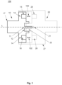
- Fig. 1 shows a side view of a plug unit coupled with another plug unit according to a first aspect of the invention.
- a plug unit 10 that can be detachably coupled to another plug unit 20.
- the plug unit 10 comprises an interface that, in the coupled arrangement, is opposite the interface of the other plug unit 20.
- the interface of the plug unit 10 comprises a power transmission device 11.
- the power transmission device 11 of the embodiment of the Fig. 1 is formed by two contact-carrying sockets 12.
- the sockets 12 are designed such that the corresponding contact-carrying pins 22 of the energy transmission device 21 of the further plug unit 20 can engage in the sockets in a form-fitting manner. By coupling, the pins 22 of the further plug unit are brought into engagement with the sockets 12 of the plug unit.
- the energy transmission devices 11; 21 are designed to transmit electrical energy between the plug unit 10 and the further plug unit. In this respect, the energy transmission device 11 of the plug unit 10 can supply the further plug unit with power and vice versa.
- the interface of the plug unit 10 in Fig. 1 a signal transmitting and/or receiving device 14, which is designed to wirelessly transmit data between the plug unit 10 and a corresponding signal transmitting and/or receiving device 24 of the further plug unit 20.
- the wireless data transmission 102 is indicated by the two double arrows in Fig. 1 marked.
- the signal transmitting and/or receiving device 14 of the Fig. 1 comprises two signal receivers and/or transmitters 15; 16, wherein the first signal receiver and/or transmitter 15 can be suitable for transmitting high-resolution image data and the second signal receiver and/or transmitter 16 can be suitable for transmitting control data. Likewise, a signal receiver and/or transmitter 15; 16 can be provided which can transmit both high-resolution image data and control data simultaneously.
- the signal transmitting and/or receiving device 24 of the further plug unit 20 can accordingly have two signal receivers and/or transmitters 25; 26 which receive control data or image data from or send control data to the first and/or second signal receiver and/or transmitter 15; 16 of the plug unit 10.
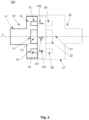
- Fig. 2 shows a side view of a plug unit coupled with another plug unit according to a second aspect of the invention.
- a second embodiment of the plug unit 10 can be seen, which can also be detachably coupled to another plug unit 20.
- the second design differs from the design of the Fig. 1 in particular in the design of the energy transmission device 11.
- the energy transmission device 11;21 in Fig. 2 has no poles or contact-carrying sockets or pins, but is based on the principle of inductive coupling 101.
- the energy transmission device 11 comprises a module 14 with an electrical coil in which an electrical current can be induced by the change in the magnetic flux through the energy transmission device 21 of the further plug unit 20 in its near field.
- Electrical energy can be transmitted from the energy transmission device 21 of the further plug unit to the energy transmission device 11 of the plug unit 10.
- Electrical energy can also be transmitted in the other direction, i.e. from the energy transmission device 11 of the plug unit 10 to the energy transmission device 21 of the further plug unit 20, wherein the energy transmission device 21 comprises a corresponding module 24 with an electrical coil.
- the energy transmission device 11 can be arranged centered in the profile of the interface of the plug unit 10.
- this arrangement has the advantage that the contact-carrying pins 22 according to Fig. 1 can be plugged into the respective sockets 12 of the plug unit 10 close to the longitudinal axis of the further plug unit 20.
- the central area of the interface should be best protected against dust or splash water when two plug units 10; 20 are coupled.
- this arrangement has the advantage that the electromagnetic field for the inductive coupling 101 can be largely shielded.
- Fig. 3 shows a side view of a plug unit coupled with another plug unit according to a third aspect of the invention, as well as a sectional plane AA through the plug unit.
- the design of the plug unit of the Fig. 3 differs from the design of the plug unit of the Fig. 2 in the arrangement of the signal transmitting and/or receiving device.
- the signal transmitting and/or receiving device in Fig. 3 comprises a first signal receiver and/or transmitter 15 and a second signal receiver and/or transmitter 16, wherein both signal receivers and/or transmitters 15; 16 are arranged substantially in concentric circles on the interface the plug unit 10.
- both plug units can be coupled to each other at any angle of rotation.
- one plug can be rotated about its longitudinal axis L relative to the other plug during operation. This makes it possible, for example, to equip a camera with such a plug so that the camera and plug can be rotated in both directions.
- the center of the concentric circles is given by the longitudinal axis of the plug unit 10.
- This design has the advantage that the plug unit 10 is rotationally symmetrical, i.e. can be coupled in any position with another plug unit 20.
- the energy transmission device 11 is also arranged essentially round and centered in the interface of the plug unit 10, as in the section plane AA of the Fig. 3 visible.
- the plug unit 10 can be detachably coupled with another plug unit 20, as shown in the view of the Figures 1 to 3 shown.
- a locking device can be provided on the housing 17 of the plug unit 10 or on the housing 27 of the further plug unit 20 (not shown).
- This locking device can be a spring-loaded clamping device, for example, or a magnetic device.
- a camera in particular a camera that can be rotated through 360°, can be connected to a carriage of a sewer inspection and/or maintenance system.
- the camera can be supplied with power via the energy transmission device 11 by means of inductive coupling 101.
- the camera can be controlled and its image data can be transmitted to a control unit of the carriage via the at least one, preferably bidirectional, wireless communication connection 102.
- an additional light can be connected to a carriage by means of the device 100.
- a lift in particular a telescopic lift, can be connected to a carriage by means of the device 100.
- the lift can be controlled by means of the wireless communication connection 102 and supplied with power by the inductive coupling 101.
- a camera and/or an additional light can in turn be connected to the lifter by means of the device 100.
- the plug unit according to the invention enables an easy-to-manufacture, low-maintenance and safe modular extension of components of the sewer inspection and/or maintenance system.
- a trolley can be connected to a cable drum by means of the device 100, wherein the cable drum can supply the trolley with power by means of the inductive coupling 101 and can transmit control data to the trolley or receive useful data from the trolley, such as image data, by means of the at least one wireless communication connection.
- the cable drum can have a control unit.
Landscapes
- Engineering & Computer Science (AREA)
- Power Engineering (AREA)
- Health & Medical Sciences (AREA)
- Life Sciences & Earth Sciences (AREA)
- Hydrology & Water Resources (AREA)
- Public Health (AREA)
- Water Supply & Treatment (AREA)
- Computer Networks & Wireless Communication (AREA)
- Connector Housings Or Holding Contact Members (AREA)
- Arrangements For Transmission Of Measured Signals (AREA)
Priority Applications (2)
| Application Number | Priority Date | Filing Date | Title |
|---|---|---|---|
| EP23177628.7A EP4475150A1 (fr) | 2023-06-06 | 2023-06-06 | Système de connecteur pour systèmes d'inspection et/ou de maintenance de canal |
| US18/735,707 US20250055225A1 (en) | 2023-06-06 | 2024-06-06 | Plug system for sewer inspection systems and/or sewer maintenance systems |
Applications Claiming Priority (1)
| Application Number | Priority Date | Filing Date | Title |
|---|---|---|---|
| EP23177628.7A EP4475150A1 (fr) | 2023-06-06 | 2023-06-06 | Système de connecteur pour systèmes d'inspection et/ou de maintenance de canal |
Publications (1)
| Publication Number | Publication Date |
|---|---|
| EP4475150A1 true EP4475150A1 (fr) | 2024-12-11 |
Family
ID=86693076
Family Applications (1)
| Application Number | Title | Priority Date | Filing Date |
|---|---|---|---|
| EP23177628.7A Pending EP4475150A1 (fr) | 2023-06-06 | 2023-06-06 | Système de connecteur pour systèmes d'inspection et/ou de maintenance de canal |
Country Status (2)
| Country | Link |
|---|---|
| US (1) | US20250055225A1 (fr) |
| EP (1) | EP4475150A1 (fr) |
Citations (7)
| Publication number | Priority date | Publication date | Assignee | Title |
|---|---|---|---|---|
| EP0440336A2 (fr) * | 1990-01-08 | 1991-08-07 | Amphenol Corporation | Connecteur électrique |
| DE4229566A1 (de) * | 1992-09-04 | 1994-03-10 | Rosenberger Hochfrequenztech | Verfahren und Vorrichtung zur automatischen Erkennung eines über eine Stecker-Buchsenverbindung an ein Versorgungsgerät angeschlossenen Anschlußgerätes |
| EP1206012A2 (fr) * | 2000-11-07 | 2002-05-15 | Endress + Hauser Conducta Gesellschaft für Mess- und Regeltechnik mbH + Co. | Connecteur pour connecter une ligne de transmision à au mois un senseur |
| WO2007045914A2 (fr) * | 2005-10-21 | 2007-04-26 | ALLAN, Elsie Anne | Interface d'outil et procede |
| EP2890020A2 (fr) * | 2013-12-26 | 2015-07-01 | Hosiden Corporation | Connecteur mâle, connecteur femelle et structure de connexion d'un connecteur mâle et connecteur femelle |
| WO2018048396A1 (fr) * | 2016-09-07 | 2018-03-15 | Fmc Technologies, Inc. | Connecteur étanche de traversée électrique sans fil |
| EP3561826A1 (fr) * | 2018-04-27 | 2019-10-30 | Yazaki Corporation | Connecteur et système d'alimentation électrique |
-
2023
- 2023-06-06 EP EP23177628.7A patent/EP4475150A1/fr active Pending
-
2024
- 2024-06-06 US US18/735,707 patent/US20250055225A1/en active Pending
Patent Citations (7)
| Publication number | Priority date | Publication date | Assignee | Title |
|---|---|---|---|---|
| EP0440336A2 (fr) * | 1990-01-08 | 1991-08-07 | Amphenol Corporation | Connecteur électrique |
| DE4229566A1 (de) * | 1992-09-04 | 1994-03-10 | Rosenberger Hochfrequenztech | Verfahren und Vorrichtung zur automatischen Erkennung eines über eine Stecker-Buchsenverbindung an ein Versorgungsgerät angeschlossenen Anschlußgerätes |
| EP1206012A2 (fr) * | 2000-11-07 | 2002-05-15 | Endress + Hauser Conducta Gesellschaft für Mess- und Regeltechnik mbH + Co. | Connecteur pour connecter une ligne de transmision à au mois un senseur |
| WO2007045914A2 (fr) * | 2005-10-21 | 2007-04-26 | ALLAN, Elsie Anne | Interface d'outil et procede |
| EP2890020A2 (fr) * | 2013-12-26 | 2015-07-01 | Hosiden Corporation | Connecteur mâle, connecteur femelle et structure de connexion d'un connecteur mâle et connecteur femelle |
| WO2018048396A1 (fr) * | 2016-09-07 | 2018-03-15 | Fmc Technologies, Inc. | Connecteur étanche de traversée électrique sans fil |
| EP3561826A1 (fr) * | 2018-04-27 | 2019-10-30 | Yazaki Corporation | Connecteur et système d'alimentation électrique |
Also Published As
| Publication number | Publication date |
|---|---|
| US20250055225A1 (en) | 2025-02-13 |
Similar Documents
| Publication | Publication Date | Title |
|---|---|---|
| EP3030470B1 (fr) | Accouplement à contacts électriques pour véhicule guidé sur rails | |
| EP3133213B1 (fr) | Dispositif de changement rapide pour utilisation entre un engin de chantier et un accessoire | |
| DE102012212254B3 (de) | Verbinder zur leitungsungebundenen Signalübertragung | |
| EP0982215B1 (fr) | Ensemble pour véhicule ferroviaire, composé d'un accouplement central et d'un accouplement de câbles électriques | |
| EP2760089B1 (fr) | Système de connexion par fiche pour le raccordement électrique d'une remorque à un véhicule tracteur | |
| WO2021140091A1 (fr) | Agencement de connecteur enfichable et connecteur électrique enfichable | |
| EP3203591A1 (fr) | Connecteur a fiches | |
| EP1936752B1 (fr) | Connecteur coaxial modulaire | |
| EP3280629A1 (fr) | Dispositif de transfert de données et/ou de signaux | |
| EP4013659A1 (fr) | Couplage de traction électrique et couplage de traction équipé dudit couplage de traction électrique | |
| EP4475150A1 (fr) | Système de connecteur pour systèmes d'inspection et/ou de maintenance de canal | |
| DE102021208655B4 (de) | Rohrleitungsinspektions- und/oder bearbeitungsgerät | |
| DE202023103106U1 (de) | Steckersystem für Kanalinspektions- und/oder Wartungssysteme | |
| EP3174773B1 (fr) | Couplage de contact électrique équipé d'un connecteur transversal | |
| DE102016209472A1 (de) | Steckersystem sowie Steckerelement | |
| DE69333748T2 (de) | Anordnung zur automatischen kontrolle von verbindungen in elektrischen hochspannungsleitungen | |
| EP2466604B1 (fr) | Unité d'entraînement pour le fonctionnement d'un interrupteur d'une installation de commutation à moyenne ou haute tension | |
| WO2016015963A1 (fr) | Dispositif d'accouplement de contact électrique comportant une interface | |
| DE102020121222A1 (de) | Hermaphroditischer Stecker | |
| EP1684385A2 (fr) | Système électrique pour un véhicule ferroviaire | |
| EP4474875A1 (fr) | Connecteur et système de connecteur pour un système d'inspection et/ou de maintenance de canal | |
| DE102023121602A1 (de) | Ladestecker zur Übertragung von elektrischer Energie und elektrischen Signalen | |
| DE202023103107U1 (de) | Stecker und Steckersystem für ein Kanalinspektions- und/oder Wartungssystem | |
| DE102005037057B4 (de) | Optische Steckverbindung | |
| EP4475456A1 (fr) | Système de transmission de données entre des composants d'un système d'inspection de canal et/ou de maintenance |
Legal Events
| Date | Code | Title | Description |
|---|---|---|---|
| PUAI | Public reference made under article 153(3) epc to a published international application that has entered the european phase |
Free format text: ORIGINAL CODE: 0009012 |
|
| STAA | Information on the status of an ep patent application or granted ep patent |
Free format text: STATUS: THE APPLICATION HAS BEEN PUBLISHED |
|
| AK | Designated contracting states |
Kind code of ref document: A1 Designated state(s): AL AT BE BG CH CY CZ DE DK EE ES FI FR GB GR HR HU IE IS IT LI LT LU LV MC ME MK MT NL NO PL PT RO RS SE SI SK SM TR |
|
| STAA | Information on the status of an ep patent application or granted ep patent |
Free format text: STATUS: REQUEST FOR EXAMINATION WAS MADE |
|
| 17P | Request for examination filed |
Effective date: 20250611 |