EP4477108A1 - Produit de soin personnel, en particulier un produit d'hygiène buccale - Google Patents
Produit de soin personnel, en particulier un produit d'hygiène buccale Download PDFInfo
- Publication number
- EP4477108A1 EP4477108A1 EP23179143.5A EP23179143A EP4477108A1 EP 4477108 A1 EP4477108 A1 EP 4477108A1 EP 23179143 A EP23179143 A EP 23179143A EP 4477108 A1 EP4477108 A1 EP 4477108A1
- Authority
- EP
- European Patent Office
- Prior art keywords
- switching element
- switching
- cap
- oral hygiene
- unit
- Prior art date
- Legal status (The legal status is an assumption and is not a legal conclusion. Google has not performed a legal analysis and makes no representation as to the accuracy of the status listed.)
- Pending
Links
Images


Classifications
-
- A—HUMAN NECESSITIES
- A46—BRUSHWARE
- A46B—BRUSHES
- A46B15/00—Other brushes; Brushes with additional arrangements
- A46B15/0087—Brushes with decoration on or in the handle
-
- A—HUMAN NECESSITIES
- A46—BRUSHWARE
- A46B—BRUSHES
- A46B15/00—Other brushes; Brushes with additional arrangements
- A46B15/0085—Brushes provided with an identification, marking device or design
-
- A—HUMAN NECESSITIES
- A46—BRUSHWARE
- A46B—BRUSHES
- A46B15/00—Other brushes; Brushes with additional arrangements
- A46B15/0089—Brushes with figurines such as animals on the handle
-
- A—HUMAN NECESSITIES
- A46—BRUSHWARE
- A46B—BRUSHES
- A46B2200/00—Brushes characterized by their functions, uses or applications
- A46B2200/10—For human or animal care
- A46B2200/1066—Toothbrush for cleaning the teeth or dentures
Definitions
- the invention relates to a personal care product, in particular an oral hygiene product, preferably a toothbrush.
- An oral hygiene product in particular a toothbrush, with at least one application unit, with at least one handle unit and with at least one functional unit which is arranged on the application unit and/or the handle unit has already been proposed.
- the object of the invention is in particular to provide a generic device with improved properties in terms of functionality and/or comfort and/or cleaning results.
- the object is achieved according to the invention by the features of patent claims 1 and 21, while advantageous embodiments and further developments of the invention can be found in the subclaims.
- the invention is based on a personal care product, in particular an oral hygiene product, preferably a toothbrush, with at least one application unit, with at least one handle unit and with at least one functional unit which is arranged on the application unit and/or the handle unit.
- a personal care product in particular an oral hygiene product, preferably a toothbrush
- at least one application unit with at least one handle unit and with at least one functional unit which is arranged on the application unit and/or the handle unit.
- the at least one functional unit has at least one, in particular one-piece, mechanical switching element which consists of an elastic material and which has at least two defined static, mutually different states.
- the functional unit can in particular have various functions, such as, among others, a cleaning function, a Information function, a protective function, a counting function, a reminder function, a design function, an animation function, a reservoir function, a comfort function, such as in particular a gripping function, a handling function and/or an employment function.
- the functional unit is preferably arranged on the application unit or on the gripping unit. However, it would also be conceivable for several functional units to be provided, with one functional unit being arranged on the application unit and one functional unit on the handle unit.
- the functional unit When arranged on the handle unit, the functional unit preferably functionally forms a part of the handle unit. When arranged on the application unit, the functional unit preferably functionally forms a part of the application unit.
- the functional unit is preferably arranged firmly, in particular captively, on the handle unit and/or the application unit, in particular on a carrier body of the handle unit and/or the application unit.
- the switching element preferably consists of a soft component; alternatively, materials for injected bristles or, at most, individual thin-walled hard components are also possible.
- the switching element can be moved from one static state to the other static state by an operator manually or with a simple tool, whereby the switching element preferably jumps into the respective static state automatically when approaching the respective static state.
- the switching element has a function for the actual application and/or an additional function.
- the switching element can create a play element, for example for a child's toothbrush.
- the function of the switching element can be used for a non-playful application, e.g. as a clamping element.
- the switching element can also perform several of the functions listed.
- the handle unit and/or the application unit has a carrier body which is provided for a direct connection of the at least one switching element.
- the carrier body is formed in particular by a base body of the handle unit and/or by a base body of the application unit.
- the carrier body is rigid so that it can form the basis for the switching element.
- the carrier body consists in particular of a hard component.
- the carrier body is arranged at least partially around the switching element.
- the switching element can be used to switch back and forth between different functions, or at least one function can be switched on.
- a function can be assigned to each static state.
- a high level of comfort can be provided.
- a cleaning result can be positively influenced.
- an adjustable switching element can be provided which has at least two fixed positions or end positions, each of which forms a state of equilibrium. Between the states of equilibrium there are in particular transition states, each of which forms intermediate positions. The transition states are not stable and the switching element switches to one or the other state of equilibrium without any significant load.
- the states of equilibrium are each along a movement vector in one direction or the other.
- oral hygiene product is to be understood in particular as a toothbrush and/or an interdental cleaner and/or a flosser and/or a tongue cleaner and/or a toothpick.
- the oral hygiene product is advantageously designed as a toothbrush, in particular a manual toothbrush, preferably a child's or adult's toothbrush, advantageously a purely manual toothbrush.
- the oral hygiene product is different from an electric toothbrush.
- the oral hygiene product can be a disposable toothbrush, a reusable toothbrush or a replaceable head toothbrush.
- the personal care product could also generally be formed by a brush product.
- a "brush product” is to be understood in particular as an oral hygiene brush and/or a cosmetic brush and/or a hairbrush and/or a household brush.
- oral hygiene brushes include manual toothbrushes such as reusable toothbrushes, replaceable head toothbrushes, disposable toothbrushes or single-tuft brushes, electric toothbrushes, as well as hybrid toothbrushes, interdental cleaners, in particular with twisted bristles (also called interdental brushes), in injected form or as flossers and/or tongue cleaners.
- Examples of personal care or cosmetic brushes include mascara brushes, nail polish brushes, face brushes, applicators, in particular hair dye applicators, massage devices, make-up brushes, Shaving brushes and/or wet razors or other personal care products are conceivable.
- Household brushes could include, for example, dishwashing brushes, floor mops and/or brooms. As a result, the statements for oral hygiene products also apply to the personal care products mentioned.
- the oral hygiene product has in particular a longitudinal axis which is advantageously arranged at least substantially parallel to a main direction of extension of the oral hygiene product.
- the longitudinal axis preferably runs at least in sections within the oral hygiene product and in particular through its center of gravity.
- the longitudinal axis of the oral hygiene product is a central axis of the oral hygiene product and/or a central axis of the handle unit.
- a "central axis" of an object is to be understood in particular as an imaginary axis which runs within the object parallel to a main direction of extension of the object and intersects the object at a maximum of two points.
- At least substantially parallel is to be understood here in particular as an alignment of a direction relative to a reference direction, in particular in a plane, wherein the direction has a deviation from the reference direction in particular of less than 8°, advantageously less than 5° and particularly advantageously less than 2°.
- a "main extension direction” of an object is to be understood in particular as a direction that runs parallel to a longest edge of a smallest imaginary cuboid that just completely encloses the object.
- a “main extension” of an object in this context is to be understood in particular as an extension of a longest edge of a smallest imaginary cuboid that just completely encloses the object.
- the oral hygiene product has a length, in particular parallel to the longitudinal axis of the oral hygiene product, of at least 110 mm, advantageously of at least 130 mm and particularly advantageously of at least 150 mm and/or of at most 200 mm, advantageously of at most 190 mm and particularly advantageously of at most 180 mm, although of course other, in particular smaller or larger, lengths are also conceivable.
- the oral hygiene product has a maximum width, in particular parallel to a width axis of the oral hygiene product, advantageously perpendicular to the longitudinal axis and/or parallel to a main extension plane of the oral hygiene product and/or the handle unit, of at least 15 mm, advantageously of at least 20 mm and particularly advantageously of at least 23 mm and/or of at most 40 mm, advantageously of at most 35 mm and particularly advantageously of at most 31 mm.
- the oral hygiene product has a maximum height, in particular measured parallel to a height axis of the oral hygiene product, advantageously measured perpendicular to the longitudinal axis of the oral hygiene product and/or perpendicular to the main extension plane of the oral hygiene product, of at least 10 mm, advantageously of at least 12 mm and particularly advantageously of at least 15 mm and/or of at most 30 mm, advantageously of at most 26 mm and particularly advantageously of at most 23 mm.
- the term “height” here refers in particular to a state of the oral hygiene product in which it is placed, for example, on a surface such as a table top, a wash basin, the top of a piece of furniture or the like, in particular such that the longitudinal axis is arranged parallel to the surface.
- a "main extension plane" of an object is to be understood in particular as a plane which is parallel to a largest side surface of a smallest imaginary cuboid which just completely encloses the object and in particular runs through the center of the cuboid.
- the application unit advantageously has at least one cleaning area, which is intended for a tooth and/or tongue cleaning application, in particular in the user's mouth.
- the cleaning area preferably comprises at least one cleaning unit, in particular at least one brush head, advantageously a toothbrush head, preferably with several bristles and/or bundles of bristles and/or injected cleaning elements or injected bristles and/or soft-elastic cleaning elements.
- the cleaning unit can also be designed, for example, as an interdental brush and/or as a single tuft (e.g. single large bundle of bristles) and/or as a bow covered with dental floss, in particular as a flosser, or the like.
- the application unit advantageously has at least the neck element, which is preferably connected to the cleaning area, in particular directly and/or in one piece.
- the term "one-piece” is to be understood in particular as being connected at least in a material-locking manner, for example by a welding process, an adhesive process, an injection-moulding process and/or another process that appears to be reasonable to the person skilled in the art, and/or advantageously formed in one piece, such as by being manufactured from a single casting and/or by being manufactured using a single or multi-component injection moulding process and advantageously from a single blank.
- "Intended” is to be understood in particular as specially designed and/or equipped.
- the fact that an object is intended for a specific function is to be understood in particular as meaning that the object fulfills and/or carries out this specific function in at least one application and/or operating state.
- the oral hygiene product has in particular a front side and a back side, which are arranged in particular facing away from one another.
- the cleaning area is arranged on the front side of the oral hygiene product.
- the front side is in particular a side of the oral hygiene product that is visible in a viewing direction perpendicular to the longitudinal axis of the oral hygiene product and perpendicular to the width axis of the oral hygiene product.
- the front side of the oral hygiene product is in particular the side of the brush on which the thumb is placed.
- the front side is normally also the side towards which the bristle field is directed.
- the back side advantageously corresponds to a side of the oral hygiene product that is visible in a viewing direction opposite to this.
- the back side of the oral hygiene product is the side of the toothbrush opposite the bristle field.
- the left side of the oral hygiene product is in particular a side that is on the left when looking perpendicularly at the front side of the oral hygiene product.
- the right side of the oral hygiene product is particularly referred to as a side that is on the right when looking perpendicularly at the front of the oral hygiene product.
- the top side is particularly referred to as an end of the oral hygiene product on which the cleaning area is arranged.
- the bottom side is particularly referred to as an end of the oral hygiene product opposite the top side, which is closest to the handle area.
- the handle unit preferably has at least one handle element, which is advantageously designed to be held with one hand.
- the handle element is preferably tapered at least in some areas. This advantageously allows a secure hold and optimizes ergonomics.
- the handle element is particularly preferably elongated, with a longitudinal axis of the handle element advantageously corresponding to the longitudinal axis of the oral hygiene product.
- the handle element is at least partially, in particular completely, formed from at least one hard component. It would also be conceivable for the handle element to additionally consist of one or more soft components. is formed.
- the material volume body is formed at least to a large extent, in particular completely, from at least one hard component.
- the grip element advantageously comprises at least one thumb grip area and/or at least one hand grip area.
- the thumb grip area is advantageously arranged on the front side of the oral hygiene product and in particular on a front side of the grip element. It is conceivable that the thumb grip area and/or the hand grip area have at least one element and/or a surface structure made of at least one soft component and/or at least one hard component.
- the grip region advantageously has at least one handle element.
- a main extension direction of the handle element is arranged at least substantially parallel to the longitudinal axis of the oral hygiene product.
- the handle element has at least one surface structure element, particularly advantageously a plurality of surface structure elements, which are at least substantially identical or at least geometrically similar to the surface structure elements of the thumb grip region described above.
- the surface structure elements of the handle element are arranged, in particular at least in pairs, one behind the other in groups along the longitudinal axis of the oral hygiene product.
- the materials used can be recyclable materials.
- recyclable materials it is advantageous to be able to recycle them after use.
- Materials that can be included in an existing recycling stream such as polyester (PET), polyethylene (PE), polypropylene (PP), are particularly preferred.
- the materials used can be recycled materials. Materials that come from a recycling stream such as polyester (rPET), polyethylene (rPE), polypropylene (rPP) are particularly preferred.
- hard component and soft component
- hard components that can be used are styrene polymers such as styrene acrylonitrile (SAN), polystyrene (PS), acrylonitrile butadiene styrene (ABS), styrene methyl methacrylate (SMMA), styrene butadiene (SB) or the like.
- a hard component can also comprise polyolefins such as polypropylene (PP), polyethylene (PE) or the like, in particular also in the form of high-density polyethylene (HDPE) or low-density polyethylene (LDPE).
- Polyesters such as polyethylene terephthalate (PET), in particular in the form of acid-modified polyethylene terephthalate (PETA), glycol-modified polyethylene terephthalate (PETG), polybutylene terephthalate (PBT), acid-modified polycyclohexylenedimethylene terephthalate (PCT-A), glycol-modified polycyclohexylenedimethylene terephthalate (PCT-G) or the like are also possible.
- Cellulose derivatives such as cellulose acetate (CA), Cellulose acetobutyrate (CAB), cellulose propionate (CP), cellulose acetate phthalate (CAP), cellulose butyrate (CB) or the like are conceivable.
- a hard component can comprise, for example, polyamides (PA) such as PA 6.6, PA 6.10, PA 6.12 or the like, polymethyl methacrylate (PMMA), polycarbonate (PC), polyoxymethylene (POM), polyvinyl chloride (PVC), polyurethane (PUR), polyamide (PA) or the like.
- PA polyamide
- PE polyethylene
- PU polyurethane
- a hard component has an elastic modulus of at least 1000 N/mm 2 and advantageously of at least 1300 N/mm 2 and/or of at most 2400 N/mm 2 and advantageously of at most 1800 N/mm 2.
- Polypropylene (PP) is preferably used as the hard component. At least certain materials mentioned under the hard component can be sustainable materials. In particular, materials with a cellulose content are at least partially bio-based.
- Hard components are advantageously used for stable and/or structural elements, in particular in the handle element and/or in a carrier element of the application unit and/or the fastening unit or the like.
- the oral hygiene product or at least one base body of the oral hygiene product has a single hard component, which can be made from one of the materials mentioned or from a mixture thereof.
- combinations of different hard components are also conceivable, whereby these can be processed in a two- and/or multi-component injection molding process and/or glued and/or welded together, in particular ultrasonically welded.
- several hard components can be used which do not form a material bond in a two- and/or multi-component injection molding process.
- a form fit for example in the form of at least one undercut and/or at least one opening and/or at least an at least partial overmolding or the like, is created between hard components.
- a second hard component which is in particular injected onto a first hard component, shrinks and/or shrinks after injection molding and advantageously forms a shrinkage connection.
- Suitable combinations can be, for example, polypropylene-polyester, polypropylene-sustainable material, polypropylene-styrene-acrylonitrile or other combinations. In this combination, polypropylene is used to create a material-tight connection with the soft component.
- Soft components can be, for example, thermoplastic styrene elastomers (TPE-S) such as a styrene-ethylene-butylene-styrene copolymer (SEBS), a styrene-butadiene-styrene copolymer (SBS) or the like. It is also conceivable to use thermoplastic polyurethane elastomers (TPE-U), thermoplastic polyamide elastomers (TPE-A), thermoplastic polyolefin elastomers (TPE-O), thermoplastic polyester elastomers (TPE-E) or the like.
- a soft component can also comprise at least one silicone, for example.
- a soft component advantageously has a Shore A hardness of at most 90, advantageously of at most 50 and particularly advantageously of at most 30.
- at least one soft component forms at least one material bond with at least one hard component, in particular in at least one two- and/or multi-component injection molding, advantageously by means of at least one overmolding and/or overmolding.
- the materials mentioned under the soft component can be at least partially sustainable materials.
- the soft component can be a material mixture of sustainable material and non-sustainable soft component.
- the soft component can be a mixture of recycled polypropylene (rPP) and a soft component.
- Recycled polypropylene (rPP) can be a raw material for producing a soft component.
- the weight proportion of recycled polypropylene in the soft component is more than 10%, preferably more than 20%, particularly preferably more than 30%.
- a hard component used and a soft component used have different colors, so that surface structures, labels, motifs and the like can be realized by means of a suitable design of the base body and the soft element.
- the at least one application unit has a brush head, in particular a toothbrush head.
- the application unit advantageously has at least one cleaning unit, in particular a toothbrush head, with bristles.
- the cleaning unit also advantageously has at least one bristle carrier, for example a brush head base body.
- At least some or all of the bristles are advantageously conventional extruded bristles.
- Bristles can in particular comprise at least one hard component and/or at least one soft component.
- the bristles are made at least partially or completely from polyamide (PA) and/or polyester (PBT, PET), although any other materials (hard component or soft component) are conceivable and sustainable materials such as chitosan are also possible.
- the bristles can be made from a degradable material.
- the bristles have a tapered section and/or a variable cross-section.
- the bristles are made from a single, in particular mixed, material.
- bristles consisting of several components or materials are also conceivable, which can be produced and/or manufactured in particular by means of at least one coextrusion.
- the bristles can be produced and/or manufactured, for example, by means of extrusion, cutting to length and/or post-processing.
- conventional bristles are extruded, cut, processed and inserted or anchored to the toothbrush handle using an adapted process, such as the anchor punching process, the AFT process, the PTt process and/or the IMT process.
- cylindrical or pointed bristles are suitable, with any cross-sections such as polygonal, triangular, rectangular, square, elliptical, star-shaped, trapezoidal, parallelogram-shaped, rhombus-shaped or any other cross-sections being conceivable.
- different bristles can be used in a bristle bundle, but also different bristle bundles, in particular each with a specific type of bristles. Bristles and/or bristle bundles can be arranged regularly, but also irregularly.
- bristles and/or bristle bundles arranged in groups and/or adjacently can differ in terms of at least one feature such as a length, a diameter, a material, a color, a material hardness, a geometry, a point and the like, in particular alternately.
- the bristles preferably have a diameter, in particular perpendicular to their longitudinal axis, of at least 0.075 mm and/or of at most 0.25 mm.
- the bristles have a cross-sectional area, in particular perpendicular to their longitudinal axis, of at least 0.002 mm 2 and/or of at most 0.2 mm 2.
- bristles used in the cosmetics sector for example bristles of an additional application element, thinner bristles and/or bristles with a smaller cross-section can also be used, in particular bristles with a diameter, in particular perpendicular to their longitudinal axis, of at least 0.025 mm and/or of at most 0.2 mm and/or with a cross-sectional area, in particular perpendicular to their longitudinal axis, of at least 0.001 mm 2 and/or of at most 0.15 mm 2 .
- polyester PBT, PET or PTT
- tapering can be produced mechanically and/or chemically.
- the bristles are preferably straight in the longitudinal direction, but wavy and/or twisted and/or helical and/or twisted bristles are also conceivable, as are combinations of different bristles. Bristles with a smooth surface are also conceivable, as are bristles with a textured surface.
- the bristles are preferably processed, in particular fastened to the bristle carrier, by means of at least one anchor punching process, an anchor-free tufting process (AFT), an in-mold tufting process (IMT), a PTt process or the like.
- the bristle carrier preferably has a plurality of bristle receptacles, in particular holes for bristle bundles, in particular drilled and/or formed during injection molding.
- anchor punching it is conceivable, for example, that a base body, in particular from a hard component, preferably the brush head, is first manufactured by means of injection molding, with blind holes for bristle bundles advantageously being formed during injection molding. Of course, subsequent drilling of blind holes is also conceivable. Bristles or bristle bundles are preferably then folded and fastened in a blind hole by means of at least one anchor, in particular by means of punching. Loop punching is also conceivable.
- anchor-free processes are also conceivable, whereby bristles or bristle bundles are advantageously not folded.
- bristles or bristle bundles are approximately half the length compared to anchor punching.
- the bristle bundles are initially separated, fused and/or the bristle ends are then overmolded, in particular for their attachment.
- bristle bundles can advantageously be brought together.
- Production using the in-mold tufting process is possible, whereby a base body, for example the brush head and/or the handle unit and/or the attachment unit, is advantageously formed during the overmolding of the bristle ends.
- bristles are first overmolded with plates or the like and these plates are then overmolded in turn, for example to form the brush head and/or the handle unit.
- the application unit is composed of a base body and a bristle plate, which is equipped with bristles and/or alternative cleaning elements.
- bristle plates with through holes are first manufactured by injection molding, through which bristles are then guided.
- the bristles are then preferably connected on a rear side, in particular fused, preferably with each other and/or with the corresponding bristle plate.
- bristle plates with bristles can then be welded and/or glued to a base body, in particular a brush head, preferably by means of ultrasonic welding.
- the base body, in particular the brush head has in particular a recess into which the bristle plate can be inserted.
- a known manufacturing process in this context is the anchor-free tufting process, which in particular enables bundles of bristles to be brought together.
- the underside of the bristle plate is in particular a side which is placed in a recess in the base body and faces towards the rear of the oral hygiene product. Accordingly, the top of the bristle plate points towards the top of the oral hygiene product.
- Another method for anchorless bristles is the manufacture, in particular injection molding, of a brush head with through holes for bristles. Bristles can then be guided through the through holes and fused on a back side, in particular with each other and/or with the brush head. Preferably, the fused areas and/or the brush head are then overmolded, in particular with at least one soft component.
- a brush head with blind holes for example by means of injection molding and/or by drilling the blind holes.
- bristles are in particular put together in bundles and fused and/or otherwise connected at one end.
- the brush head is then heated, in particular to a glass temperature of its material.
- Bristle bundles can then advantageously be inserted into the blind holes and anchored to the brush head by pressing them on.
- the heated blind holes or their surroundings are deformed so that the bristle bundles are anchored in them.
- injection-molded bristles are also conceivable. These can be manufactured together with the application unit, the handle unit and/or the fastening unit, in particular during multi-component injection molding, or can be subsequently injection-molded onto a base body of the application unit.
- filament is fed from a roll, with several filament strands wound onto a roll.
- Several rolls are pre-tensioned for machine feeding, because each filament in the brush corresponds to a filament strand.
- the filaments are spread out correctly in width so that they are the width at which they are inserted into the brush.
- the filaments are pulled forward so that they are then free for the next step, i.e. so that a wire can be guided over them.
- a wire is then fed from a roll onto the machine, i.e. unwound and introduced into the process.
- the wire is cut to a length that is greater than the unwound length of the twisted brush, and the final cutting to length takes place after twisting.
- the wire is bent into a U so that the open side can then be pushed over the filaments to thread the bristles.
- the wire is held at the bottom of the U.
- the open end of the wire is then clamped so that the filaments are held between the pieces of wire.
- the filaments are cut to a length that is longer than the final length in the brush so that the brush can be cut correctly once the filaments are twisted in.
- the wire is twisted so that the filaments are clamped between the wire and thus After the filaments are fixed in the wire, they are cut to the correct length and profiled. After the brush part is finished, the excess wire is cut off.
- materials of injected bristles do not form a material bond with other soft components and/or hard components and/or sustainable materials of the oral hygiene product during an injection molding process, in particular a two- and/or multi-component injection molding.
- injected bristles are preferably connected to soft components and/or hard components by means of a positive connection, for example by means of at least one undercut and/or at least one opening and/or by means of at least partial overmolding, with a shrinkage connection and/or a shrinkage connection being conceivable in particular.
- a connection by means of at least one material connection is also conceivable.
- one-, two- and/or multi-component injection molding is basically conceivable.
- Materials used in particular different soft components and/or hard components, can be and/or be connected in a material-locking and/or form-fitting manner, as mentioned. It is also conceivable to form articulated, movable or flexible connections using suitable injection molding steps. Hot runner processes, cold runner processes and/or co-injection processes are basically possible, for example.
- the application unit can also have at least one tongue cleaner and/or at least one alternative cleaning and/or massage element.
- These can each be formed from a soft component, a hard component or a combination of soft and hard components and/or can advantageously be manufactured and/or produced by means of injection molding.
- injection-molded bristles are formed at least partially and advantageously completely from a thermoplastic polyurethane elastomer (TPE-U).
- TPE-U thermoplastic polyurethane elastomer
- TPE-E thermoplastic polyester elastomers
- TPE-A thermoplastic polyamide elastomers
- PE polyethylene
- LLDPE linear low density polyethylene
- Materials for injected bristles advantageously have a Shore D hardness of at least 0 and particularly advantageously of at least 30 and/or of at most 100 and advantageously of at most 80.
- a Shore hardness of a material for injected bristles is advantageously higher than a Shore hardness of other soft components used, for example for handle elements, massage elements, other cleaning elements or the like.
- the materials used to produce injected bristles can be sustainable materials.
- water-soluble polymers are also conceivable, for example for hard components, soft components, injected bristles or other elements of the oral hygiene product.
- sustainable materials in particular bioplastics
- Raw materials in particular include corn, hemp, sugar, castor oil, palm oil, potatoes, wheat, sugar cane, sugar beet, rice husks, rubber, wood, the castor plant / castor oil plant and the like.
- Possible basic materials could be, for example, cellulose, starch, lactic acid (PLA), glucose, chitin, chitosan, lignin, casein, gelatin or the like, from which corresponding bioplastics in particular can be synthesized.
- bioplastics preferred here include starch-based bioplastics, cellulose-based bioplastics, polyhydroxyalkanoates (e.g. polyhydroxybutyric acid (PHB)), polylactic acid (PLA) or aliphatic/aromatic copolyesters.
- PHB polyhydroxybutyric acid
- PLA polylactic acid
- Other preferred bioplastics include lignin-based bioplastics.
- a "functional unit” is to be understood in particular as a unit which is intended to provide an additional and/or extended function of the oral hygiene product.
- the unit is intended to provide a function, in particular a function that goes beyond a basic function, on the oral hygiene product permanently or optionally.
- Various functions that appear useful to a person skilled in the art are conceivable, such as a cleaning function, an information function, a protection function, a counting function, a reminder function, a design function, an animation function, a reservoir function, a comfort function, such as in particular a gripping function, a handling function, a marking function and/or an activity function.
- a cleaning function a cleaning function that goes beyond the basic cleaning function can be provided in particular by means of the functional unit.
- a "mechanical switching element” is to be understood in particular as an element which can be switched mechanically, in particular manually or with a simple tool, between different states and/or positions.
- the mechanical switching element has several, in particular at least two defined static states that are different from one another. It is also conceivable that the switching element can assume several stable states, such as 3, 4 or 5 states.
- the mechanical switching element is elastically deflected in at least one of the defined static states.
- at least one static state forms a relaxed state of the mechanical switching element.
- the mechanical switching element can be brought from a first static state, in particular a rest state, by elastic deformation into a further static state, which is significantly different from the first state in terms of shape and/or orientation.
- the switching element can be brought manually by an operator from a static state to the further static state, wherein the switching element preferably jumps into the respective static state, in particular automatically, when approaching the respective static state.
- the mechanical switching element consists of a soft component or an elastic material, such as an elastomer or a silicone.
- the switching element has at least one Switching cap which is dome-shaped, in particular hemispherical, in the first state, in particular the rest state.
- the switching cap can preferably be turned inside out so that a dome is formed on an opposite side.
- the switching element is in particular designed as a "pop it” or “push pop”.
- the switching cap is preferably designed in particular as a single "pop it” or “push pop” curvature.
- the mechanical switching element is preferably designed in one piece. "One piece” is to be understood in particular as being formed in one piece. This one piece is preferably made from a single blank, a mass and/or a cast, particularly preferably in an injection molding process, in particular a single and/or multi-component injection molding process.
- the switching element is in particular formed by an elastic element.
- An “elastic element” is to be understood in particular as an element which can be repeatedly deformed without the element being mechanically damaged or destroyed as a result, and which, in particular after deformation, independently strives towards at least one of the static states.
- the aid can be a pencil, a ballpoint pen or a thin cylindrical rod.
- Smaller switching elements that are not so easy to switch can be designed intentionally, for example if switching is only rarely necessary or should not be easily possible. For example, such an element should be used for the function of displaying the end of use, since the function is set once and should not be easily changed afterwards.
- the at least one switching element preferably has exactly two defined static states that are different from one another, namely a first equilibrium state, in particular an initial state, and a second equilibrium state, in particular a deflection state.
- the first equilibrium state forms in particular a rest state of the switching element.
- the first equilibrium state forms in particular an unloaded state.
- the switching element is at least partially prestressed in the second equilibrium state, in particular the deflection state. This makes it possible in particular to specifically switch between exactly two static states.
- an operator can select and set a state that is suitable for a current application.
- the switching element can be brought manually by an operator, in particular by applying a pressure force to the switching element, from one static state to another static state. From an intermediate position between the equilibrium states, the switching element always switches to one or the other equilibrium state, depending on the intermediate position.
- the equilibrium states form in particular a rest position or a balanced position.
- the at least one switching element can in particular have an individualized feel and/or function.
- different switching elements can produce an adjustable or individual feel or shape on the oral hygiene product due to their different equilibrium states.
- functions for example for tongue cleaners, bristle fields, cleaning elements and/or other functions mentioned.
- switching elements next to each other can have different colors.
- the at least one switching element has a significant functional surface.
- the functional surface is the side that is equipped with functional elements and is directed outwards.
- the functional surface is preferably oriented towards the front of the oral hygiene product.
- the functional surface is convexly curved in the first equilibrium state and concavely curved in the second equilibrium state.
- the functional surface is dome-shaped, in particular hemispherical, in the first equilibrium state and bowl-shaped in the second equilibrium state.
- the switching element is curved in the second equilibrium state on a side opposite to the first equilibrium state.
- the switching element is convexly curved towards a front side in the first equilibrium state and convexly curved towards a back side in the second equilibrium state.
- the functional surface is formed in particular by an upper side of the switching cap of the switching element.
- the functional surface is arranged on a front side of the oral hygiene device.
- the functional surface is formed by a surface of the switching cap of the switching element facing the front side.
- a "functional surface” is to be understood as a surface of the functional unit, in particular of the switching element, which in at least one state of the switching element has a direct function, such as a display function, a cleaning function, a gripping function, an information function, a protection function, a counting function, a reminder function, a design function, an animation function, a reservoir function, and/or the like.
- Cleaning elements, display elements, a handle structure or the like can preferably be arranged on the functional surface. This makes it possible to switch back and forth between different functions, in particular via the switching element, or at least one function can be switched on.
- a function can be assigned to each static state.
- an advantageously high level of comfort can be provided.
- a cleaning result can be positively influenced.
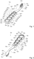
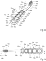
- the functional unit has at least three mechanical switching elements, each of which consists of an elastic material and each of which has at least two defined static states that are different from one another.
- the functional unit can preferably have 1, 2, 3, 4, 5, 6, 7, 8, 9, 10, 11 or 12 switching elements, preferably 1 to 6 switching elements.
- the realization of several switching elements is possible, whereby a carrier body of the application unit and/or the handle unit does not have to have the same thickness everywhere.
- the switching elements can have different shapes and/or sizes such as length, width and height.
- the first equilibrium state in particular the Rest state, with several switching elements on the oral hygiene product, can be different, for example alternating.
- the rest state can be provided differently for different functions, in particular depending on the application.
- the at least 2 or 3 mechanical switching elements are arranged next to one another.
- the switching elements are arranged in a row.
- the switching elements are arranged one behind the other along the main direction of extension of the oral hygiene product.
- the switching elements can form a regular and/or at least partially repeating structure. This can in particular provide a particularly advantageous functional unit.
- a functional surface and/or a large number of functions can be provided over a large area.
- Several switching elements with a corresponding label or illustration can, for example, be provided to be pressed in after a defined cleaning process has been completed.
- the switching elements In the case of (children's) toothbrushes, for example, it would be conceivable for the switching elements to be provided as control elements. For example, three switch elements are conceivable, each with morning, midday and evening labels or images, whereby the switch element can be pressed in after cleaning at the corresponding time of day. Alternatively, four switch elements are conceivable, each of which, like a quadrant timer, represents a quadrant of the teeth to be cleaned. The switch elements could have corresponding labels and images for quadrant 1, quadrant 2, quadrant 3 and quadrant 4. Furthermore, individual switch elements or a combination of switch elements can represent an intended period of use for the oral hygiene product. For example, 3 switch elements can represent a period of use of 3 months, with a switch element being switched after each month. Alternatively, 12 switch elements can be used to set the expected or recommended end of use, e.g. 3 months after first use, as a reminder. The month in which the end of use is reached is marked with the switched switch element.
- switching elements can be arranged in a row, for example one behind the other, on a straight or curved line (e.g. on a circle or an ellipse), or freely. It would also be conceivable for the switching elements to be arranged as a field, for example with several switching elements next to each other in two dimensions.
- the switching elements can each be arranged at different distances from each other. Preferably, the distances in one or more dimensions are constant, in particular regular. If there are several switching elements, the distances between the switching elements are measured in particular between the centers of the switching caps of the switching elements. Alternatively, the distances between the switching elements can vary. For example, it would be conceivable for the edge webs of the switching elements to lie against each other.
- the distance is the sum of 0.5*diameter of the first switching cap of the first switching element, the width of the support edge of the first switching element, the width of the edge web, the width of the support edge of the second switching element and 0.5*diameter of the second switching cap of the second switching element.
- the switching elements are arranged at different distances, they can be designed to be the same in terms of the distance resulting from the width of the respective support edges and edge webs. The distance varies between the respective centers of the switching caps.
- one switching element it is also possible for one switching element to be integrated into another switching element. For example, it would be conceivable for a small switching element to be integrated into the switching cap of a larger switching element. Furthermore, different hardnesses can be combined in one switching element, for example in the form of a softer switching cap and a harder switching cap (harder or softer is defined by the force [pressure force] required to switch a switching element). Furthermore, one switching element can be directed upwards and one switching element downwards. It would also be conceivable for both switching elements to be directed upwards or for both switching elements to be directed downwards.
- At least one switching element does not have a closed outer contour.
- a support edge of the switching element cannot be arranged around the entire switching cap.
- a collar-like arrangement can be provided, for example for an arrangement in the application unit.
- the switching element can be arranged on the edge, for example on the edge of the brush head, so that complete framing is not possible.
- switching elements with two functions can be designed, such as a toothbrush with a tongue cleaner and/or soft element in one.
- the switching elements can be arranged in a three-dimensional geometry, i.e. not flat.
- the switching elements can preferably be integrated in the form of a ball or a dome.
- the carrier body it would be conceivable in particular for the carrier body to also consist of a soft component and for the carrier body and the switching elements to be formed in one piece. It would preferably be conceivable for the switching elements to protrude from a layer of soft component of the carrier body.
- a corresponding design would be conceivable in particular if the switching elements were designed as play elements for a child's toothbrush.
- the carrier body with the switching elements could, for example, be arranged at a lower end of the oral hygiene device. Alternatively, it would also be conceivable for the entire handle unit to be designed with corresponding switching elements. This could in particular enable a reduction in the volume of the carrier body.
- the functional unit has at least two mechanical switching elements, which have a common peripheral edge web. If there are several switching elements next to each other, the edge web in particular can be continued geometrically. Furthermore, the edge web between two switching elements can be designed as a raised area in the same material as the switching element or elements. The carrier edge therefore does not lie on the carrier body everywhere.
- the handle unit has at least one handle base body, wherein the functional unit is arranged on the handle base body.
- the handle base body in particular forms a carrier body of the handle unit for receiving the functional unit.
- the functional unit can in particular be arranged only in a defined partial area, such as a thumb grip area, of the handle base body, or can be arranged distributed over the entire handle base body.
- the functional unit can be arranged, for example, between a lower end of the oral hygiene product and the thumb grip area.
- the switching element of the functional unit can, for example, represent a pop-it belly (e.g. as the belly of an animal) with a corresponding arrangement.
- the functional unit can preferably be arranged in the area of the support surface for the ball of a hand.
- the functional unit could be arranged as a thumb grip in the thumb grip area.
- the functional unit could accordingly form a pop-it thumb grip.
- the thumb grip can be protruding or inward, thus with a dome at the back or front.
- An operator can adapt the thumb grip area to his requirements in particular.
- the grip unit advantageously comprises at least one thumb grip area and/or at least one hand grip area.
- the thumb grip area is advantageously arranged on the front of the oral hygiene device and in particular on a front of the grip element. It is conceivable that the thumb grip area and/or the hand grip area have at least one element and/or a surface structure made of a soft component.
- the switching elements of the functional unit can be set or arranged (e.g. in the thumb grip area or in the application area) so that if too much pressure is exerted on the application unit during use, the switching element of the functional unit switches from the initial state to the deflection state. The user thus notices that he has applied too much force or pressure to the application unit and thus learns to use the correct pressure. The switching element can then be very easily reset to the initial state.
- the at least one switching element prefferably be in the form of a suction cup.
- two switching elements prefferably be provided, which are designed as suction cups directed towards one another and emit sounds when the load is released, in particular when separated.
- the handle base body preferably has at least one recess in which the functional unit, in particular at least one switching element of the functional unit, is arranged.
- the recess is preferably completely enclosed by the material handle base body in the main extension plane of the handle unit.
- the handle base body preferably forms at least partially a ring, in particular a loop, which extends around the functional unit.
- the recess is preferably formed by an oval recess and/or a single or multiple cambered recess.
- the base body forms in particular two lateral longitudinal webs, which are each connected at at least one end, in particular a front end and a rear end, and which enclose the recess and thus the functional unit.
- the recess can also have individual transverse webs between the switching elements.
- the ring formed by the base body, in particular the loop, which encloses the recess, is in particular designed to be closed. In particular, there are preferably no open ends, such as fork-shaped designs.
- the ring, in particular the loop can have a wide variety of cross-sections.
- Possible cross-sectional shapes are circular, oval, elliptical, rectangular, diamond-shaped, triangular, n-sided, rhombus-shaped, parallelogram-shaped, whereby the edges/corners formed in the longitudinal direction can be rounded or "sharp".
- the ring is in particular rounded or rounded on the outside, i.e. outside the recess.
- the cross-section can change along the longitudinal course and change from one shape to another shape, even several times. It would also be conceivable that several recesses are provided in the handle base body, in each of which at least one switching element of the functional unit is arranged. It would also be conceivable that only part of the Switching elements are arranged in recesses.
- Some of the recesses can also, for example, only have a frame and form a hole.
- the number of recesses can in particular be 1, 2, 3, 4, 5 or more, preferably one to three.
- the recesses can be arranged next to one another at least partially perpendicular to the longitudinal direction.
- the recess can have a wide variety of cross sections in a plan view from the front.
- the shape of the recess corresponds in particular essentially to a shape of the functional unit.
- the carrier body preferably has at least one recess.
- the carrier body can be part of the handle unit or part of the application unit.
- the carrier body has recesses or openings for the implementation of the switching element.
- the recesses form an edge for a connection of the at least one switching element.
- a connection of an edge web of the switching element is implemented in the recess.
- the recess preferably has in particular a closed contour.
- the recess does not have an angular contour.
- an angular contour with rounded corners would be conceivable.
- the recess has a round or rounded shape, such as in the form of a circle, oval or oblong.
- the recess has in particular a diameter of 8 mm to 30 mm, preferably 12 mm to 25 mm.
- a length and/or width of the recess preferably corresponds essentially to the diameter. If the recess is intended to accommodate several switching elements, the length of the recess can be different. If several switching elements are lined up, the width is based on the width of the individual switching element.
- the carrier body can in particular have a different thickness than the height of the switching element.
- the switching element is completely recessed in the recess of the carrier body, for example when arranged in a depression for the thumb grip. Alternatively, however, the switching element can also protrude from the carrier body, in particular protrude beyond an upper edge of the carrier body.
- the switching element can protrude far enough beyond the carrier body that comfortable switching with the finger is possible, ie that the finger only has to dip slightly into the recess in the carrier body in order to actuate the switching element.
- the at least one recess of the Carrier body has a closure with a straight edge.
- the height of the recess is given in particular by the fact that the switching element has to hold on to the carrier body and therefore there has to be sufficient fastening surface.
- a body thickness of the carrier body can, however, in particular be greater than the straight edge of the recess.
- the height of the edge of the recess is in particular from 3 mm to 15 mm, preferably from 5 mm to 10 mm.
- the edge forms a surface, in particular an annular surface, which extends perpendicular to the longitudinal direction of the oral hygiene product.
- the surface of the edge of the recess it would also be conceivable for the surface of the edge of the recess to be conically shaped.
- steps to be provided in the surface of the edge of the recess, whereby limits in terms of demoldability in the injection molding tool should be taken into account. Not all recesses in the carrier body have to be equipped with or filled with a switching element.
- At least some of the recesses have no filling, that at least some of the recesses are provided with a soft component only at the edge, in particular corresponding to the component of the switching element, that at least some of the recesses are completely filled or that at least some of the recesses are filled with a material film.
- the switch element can take on a movable part of an information element, a customizable surface structure, a figure, an ornament, a pictogram or a logo. This can encourage the user to use the oral hygiene product in a playful way. Furthermore, comfort during use can be increased. In addition, the intended use of the oral hygiene product can be optimized or reinforced.
- the recesses can in particular enable material savings to be made on the carrier body. Furthermore, by not completely filling the recesses, further material can be saved. This makes the oral hygiene product more sustainable and more resource-efficient.
- the at least one switching element is in particular form-fitting and/or material-fitting or material-fitting in the recess. Preferably, the switching element is connected to the carrier body in a form-fitting and/or material-fitting or material-fitting manner.
- the functional unit consists entirely of a soft component.
- the at least one switching element consists entirely of a soft component.
- the at least one switching element is arranged in a recess, in particular an opening, in the application unit and/or the handle unit, wherein the switching element is at least partially enclosed laterally by the application unit and/or the handle unit.
- the switching noise or the switching force (pressure force) of the switching element of the functional unit depends on the hardness of the soft component. The harder the soft component, the louder the popping noise or the higher the force required (pressure force) when changing between the states.
- the pressure force is further influenced by the material thicknesses, the material itself and the shape of the individual elements of the functional element, for example the width of the carrier edge and the transition from the carrier edge to the switching cap.
- the pressure force to bring the switching element from the initial state to the deflected state is between 80 grams and 160 grams, preferably between 110 grams and 150 grams.
- a pressure force of 90 grams to 130 grams, preferably 60 grams to 140 grams is required.
- Components which can be processed thermoplastically are preferably provided. TPEs or similarly soft materials are preferably used. Alternatively, the use of silicone is also conceivable.
- the at least one switching element has at least one dome-shaped, in particular hemispherical, switching cap, which is elastically deflectable.
- the switching cap is at least in the first Equilibrium state dome-shaped, in particular hemispherical.
- the switch cap is dome-shaped, in particular hemispherical, in the first equilibrium state and in the second equilibrium state.
- the switch cap forms a dome in height.
- the switch cap has in particular a closed contour.
- the shape of the switch cap is in particular (hemi-)spherical or (hemi-)ellipsoidal.
- the shape of the switch cap can be hood-, dome-, cone-, thimble- or pyramid-like.
- the shape is generally rounded.
- the switch cap has a symmetrical basic shape, which is preferably not square, but round or oval.
- the switch cap has a rounded basic shape (e.g. ellipse, circle, n-gon with rounded corners), in particular on one base side.
- the base side of the switch cap can also follow a free (e.g. figure-shaped) contour.
- a rounded basic shape ensures the function best.
- an oval or regular n-sided shape with strongly rounded corners would also be conceivable. Symmetrical shapes are particularly preferred.
- the switching cap in particular only forms part of the geometry of the switching element.
- the switching element is formed by a large rectangular element that has a round switching cap somewhere.
- the switching cap is preferably connected via an edge web.
- the edge web can be of different widths.
- a transition from the switching cap to the edge web does not have to match the geometry of the recess in the handle unit and/or the application unit. This makes it possible to provide a particularly advantageous switching element. In particular, an advantageous shape of the switching element can be achieved.
- the switch cap in one variant, it would be conceivable for the switch cap to have a non-closed layer or membrane, i.e. to be provided with recesses. It would be particularly conceivable for the switch cap to have incisions, in particular cuts towards the center, preferably spiral cuts, in which the switch cap retains a dome or spherical shape overall, or sunbeam-shaped, straight cuts. The cuts are in particular regularly and/or symmetrically distributed. However, an irregular distribution would also be conceivable.
- the number of cuts or recesses is in particular from 4 to 15, preferably from 5 to 10.
- the width of the cuts or recesses is in particular from 0.5 mm to 3 mm, preferably from 1 mm to 2 mm.
- the Center can be either closed or open. With a closed design of the center, the switching function can be better ensured. With an open center, the diameter of the opening is in particular from 0.5 mm to 5 mm, preferably from 1 mm to 2 mm.
- a (surface) structure is preferably provided on the switch cap of the at least one switch element.
- the switch cap can preferably be provided with, in particular haptic, decorative or informative elements which protrude or are recessed on the surface.
- the height or depth of the elements is in particular from 0.1 mm to 1.5 mm, preferably from 0.3 mm to 1 mm.
- the structures can be fully or partially distributed over the switch cap.
- the element can be completely filled or only represented by an outer contour.
- Possible examples of the, in particular decorative or informative, elements are ornaments, figures and/or pictograms, such as Yes/No or On/Off, motifs, such as flowers or animals, and/or geometric elements, such as grids, diamonds or knobs.
- switch caps for example morning / noon / evening or quadrant 1 / quadrant 2 / quadrant 3 / quadrant 4.
- An eroded structure is conceivable as a surface structure, for example.
- the switch cap may have a different surface structure than other zones made of soft material on the oral hygiene product.
- the switch cap may have a different surface structure than the edge bar and/or the carrier edge.
- the at least one switching element has at least one at least partially circumferential edge web for fixing the switching element, wherein the switching cap is connected to the edge web via a carrier edge.
- the edge web is provided for a direct connection to the handle unit and/or the application unit.
- the edge web serves in particular for fastening the switching element.
- the edge web extends around the switching element, wherein the edge web is designed to be spaced apart from the switching cap.
- the carrier edge is arranged between the switching cap and the edge web, which connects the switching cap to the edge web.
- the edge web forms in particular a part of the construction of the switching element or the functional unit.
- the edge web represents in particular the Connection or the connection of the switching element to the handle unit and/or the application unit is secure.
- Various implementations of the edge bar that appear sensible to a specialist are conceivable.
- various shapes are conceivable.
- the edge bar can form a haptic element of the handle unit or merge into one.
- the edge web can extend over the entire height of the recess in which the switching element is arranged.
- the edge web can also extend only over the height/thickness of the carrier edge.
- options between the first and second variants would also be conceivable.
- the edge web is in particular ring-shaped.
- the edge web directly adjoins the carrier edge on the inside.
- the carrier edge is formed between the edge web and the switching cap.
- the carrier edge preferably adjoins the edge web directly on the outside, in particular on an outer circumference.
- the carrier edge preferably adjoins the switching cap directly on the inside, in particular on an inner circumference.
- the carrier edge is in particular ring-shaped.
- the carrier edge and the edge web are round, in particular ring-shaped, around the switching cap.
- the carrier edge and/or the edge web can only form part of the circumference of the switching cap.
- the switch cap does not necessarily have to be 100% enclosed by the handle unit and/or the application unit, in particular by a carrier body of the handle unit and/or the application unit.
- the carrier edge must be designed in such a way that there is sufficient fixation of the switch cap to enable switching.
- the carrier edge to provide several connection points to the switch cap, which are separated from one another by interruptions.
- the number of connection points or interruptions is in particular from 2 to 8, preferably from 3 to 6.
- the carrier edge in particular forms partial webs.
- the arrangement of the partial webs can be regular or irregular.
- the partial webs are preferably arranged symmetrically with respect to the center of the switch cap. This makes it possible in particular to provide an advantageously stable and securely connected switch element. In particular, it can enable the switch element to be securely fixed without negatively affecting switching.
- the recess it is also possible for the recess to extend all the way around the switch element, the connection is implemented via the carrier edge but not all the way around the switch cap.
- the carrier edge is interrupted in certain parts.
- the functional unit has at least two mechanical switching elements which are connected to one another in one piece. If there are several switching elements, these can be arranged in particular in a row, for example one behind the other, on a straight or curved line, or freely. Preferably, the switching elements are arranged in particular in a row. Preferably, the switching elements are arranged one behind the other along the main extension direction of the oral hygiene product.
- the switching elements are designed to be directly adjacent to one another. This means that the number of components can be kept low. Furthermore, the functionality of the switching element can be reliably enabled. This means that a particularly advantageous functional unit can be provided. In particular, a functional surface and/or a large number of functions can be provided over a large area.
- Several Switching elements with appropriate labeling and/or images and/or arrangement can, for example, be designed to be pressed after completion of a defined time or usage or cleaning process.
- the handle base body forms a frame which directly and at least partially encloses the edge web.
- the frame in particular forms the carrier body.
- the frame directly delimits the recess which is provided for receiving the switching element.
- the frame can have connecting webs or a grid of connecting webs which delimit individual or multiple switching elements.
- the frame has an at least approximately constant cross-section.
- the handle base body has at least one thumb grip area, wherein the at least one mechanical switching element is integrated into the thumb grip area or forms at least a part of it.
- the switching element in the thumb grip area is completely enclosed by the handle base body in particular in at least one plane.
- the functional unit is arranged as a thumb grip in the thumb grip area.
- the functional unit could accordingly form a pop-it thumb grip.
- the thumb grip can be designed to protrude or indent, thus with a dome at the back or front. This means that the first equilibrium state or the functional surface can be aligned towards the front or the back. An operator can adapt the thumb grip area in particular to his requirements.
- the switching element in the thumb grip area can serve to prevent excessive pressure on the application unit.
- the switching element can be set so that if too much pressure is applied to the application unit, it changes its shape significantly or even switches to another position.
- the thumb grip area is arranged on the front of the oral hygiene device and in particular on a front of the handle element. This allows additional functions to be advantageously provided on the Handle unit, such as control functions and/or handle functions.
- At least one switching element is arranged in the neck of the oral hygiene product, in particular in the neck element of the application unit.
- switching does not work with the usual proportions of a toothbrush, as the switching element cannot be made large enough.
- a generally or partially wider design of the neck than is commonly known must therefore be aimed for.
- the switching element can serve as an indicator if too much pressure is exerted on the application unit.
- the application unit has at least one brush head, wherein the functional unit is integrated into the brush head.
- the functional unit has at least one switching element which is arranged on the brush head.
- the switching element is formed in particular by a convertible cleaning element and/or a reservoir and/or a protective cover.
- the application unit has structural or cleaning elements which are attached to the switching element.
- the cleaning elements are injection-molded and in particular made from one cast or in one operation with the switching element.
- the switching element can have the functions of contact pressure control, wherein the switching element with the cleaning elements is pushed away if too much pressure is applied and goes into a second equilibrium state.
- the switching element is integrated or embedded directly into the brush head.
- the switching element must in particular be designed to be relatively large so that switching between the states is possible.
- the cleaning elements on the switching element can be designed as bristles and/or as slats and/or knobs and/or surface structures.
- the lamellae can be formed in particular by cleaning elements which are designed as protruding webs, in particular with an extension in a further dimension compared to a bristle.
- the lamellae can be provided, for example, to provide a polishing or whitening effect.
- the switching element only serves to control the contact pressure as described above and has no real further function.
- additional functions can advantageously be provided on the application unit, such as control functions and/or cleaning functions.
- the switching element is preferably designed in particular as a functional element in the brush head.
- the switching element can preferably be formed by a switchable, in particular foldable, collar.
- the switching element can in particular form a combination of a switchable head holder or protective element and a switchable tongue cleaner or tongue cleaner edge.
- the switching element When folded up, the switching element can serve as a head holder or protective element for the bristles, which at least partially surrounds a bristle field of the brush head.
- the switching element or its edge can serve as a tongue cleaner, while the bristle field is free.
- the switching element is in particular formed by a U-shaped wall which extends around an upper edge of the brush head.
- An upper free edge of the wall can point towards the front in a first state of equilibrium or towards the back of the oral hygiene product in a second state of equilibrium.
- a combination of a switchable cleaning element and a switchable tongue cleaner would also be conceivable.
- the switching element When folded up, can form a cleaning element and when folded down, a tongue cleaner.
- a combination of a switching massage element and a switching tongue cleaner would also be conceivable.
- the switching element When folded up, the switching element can form a massage element and when folded down, a tongue cleaner.
- Further structures can be attached to the edge or surface of the switching element. The structures serve in particular to assist cleaning, such as in one case tongue cleaning and/or in the other case teeth cleaning.
- a free edge of the switching element can have various designs that appear sensible to a specialist, such as not straight but wavy, continuous or discontinuous, with knobs on the edge and/or with small bristles on the edge.
- the side surfaces of the switching element could be provided with recesses, such as in particular blind holes or through holes and/or with knobs.
- the switching element can have a structure, such as a grid, knob or eroded structure.
- the at least one switching element has a substantial functional surface, with cleaning elements being arranged on the functional surface are.
- the cleaning elements are injection-molded and in particular made from a single cast with the switching element.
- the at least one switching element has cleaning elements such as (injected) bristles and/or slats and/or knobs and/or surface structures, wherein the cleaning elements are formed in one piece with a switching cap of the switching element.
- the term "in one piece” can also be understood as one-piece.
- the cleaning elements are in particular formed in one piece with the at least one switching element.
- the functional surface is dome-shaped, in particular hemispherical, in the first equilibrium state, and bowl-shaped in the second equilibrium state.
- the functional surface is formed in particular by an upper side of the switching cap of the switching element.
- the functional surface is arranged on a front side of the oral hygiene product, in particular on a front side of the application unit.
- the functional surface is formed by a surface of the switching cap of the switching element facing the front.
- the cleaning elements are arranged in particular protruding from the functional surface. This makes it particularly advantageous to provide additional functions on the application unit, such as control functions and/or cleaning functions. It is further proposed that the cleaning elements form different cleaning patterns depending on a state of the switching element.
- the switching element preferably has the function that the cleaning field of the application unit can be partially customized. For example, in the first equilibrium state the switching element can form a differently shaped cleaning field than in the second equilibrium state. Depending on the state of the switching element, not every function is active in every state. Preferably, a partial cleaning field can be switched on using the switching element. This makes it particularly advantageous to enable a high degree of customization. Advantageous adaptability can be provided.
- the oral hygiene product is formed by a convertible tongue cleaner, with the application unit being formed by a tongue cleaner head.
- the at least one switching element is arranged at least on the application unit in a corresponding design.
- cleaning elements are arranged on the at least one switching element, in particular tongue cleaning elements, of the application unit. It is particularly provided that the cleaning elements are pushed away if too much pressure is applied.
- the at least one switching element is equipped with the cleaning elements and/or at least partially forms a cleaning element itself.
- a corresponding oral hygiene product can have switchable tongue cleaner designs.
- the cleaning surface of the tongue cleaner head has further cleaning elements.
- cleaning is carried out accordingly with the further cleaning elements or certain cleaning elements are left free in the second design.
- the tongue cleaner head it would also be conceivable for the tongue cleaner head to have two sides with two different tongue cleaners per side. In this case, it would be particularly conceivable for the switching elements to be able to be switched on at the front or the back.
- the front and back of the tongue cleaner head can each have two different designs or functions.
- Corresponding designs of the application unit can be implemented in particular as a tongue cleaner only or as a tongue cleaner integrated into the toothbrush, ie bristles for tooth cleaning are available on the front of the application unit and the described tongue cleaner head is available on the back.
- the switching element is preferably free, particularly at the back, so that it can be pushed back again.
- a design as a tongue cleaner only is particularly advantageous here.
- the switching element may have no function or a different function on the front of the application unit than on the back of the application unit and vice versa.
- the at least one switching element is not accessible from both sides.
- the at least one switching element delimits a cavity on the back in particular.
- the functional unit preferably has in particular a Reset element for the at least one switching element.
- the reset element can be formed, for example, by a pulling element which is arranged on the switching element in order to pull the switching element back into the first equilibrium state.
- the reset element can also be formed, for example, by a cleaning element at the same time.
- the reset element can be formed by a push element.
- the reset element can be formed, for example, by a rocker which presses on the switching element in the second equilibrium state and thus triggers the reset.
- the cavity delimited by the switching element may have an injection opening into which an operator can blow, for example, in order to transfer the switching element from the second equilibrium state to the first equilibrium state.
- the cavity delimited by the switching element it would also be conceivable for several switching elements to delimit a common, closed cavity, with a volume of the cavity being dimensioned such that only a defined number of switching elements can be in the first or second equilibrium state. If a switching element is transferred from one equilibrium state to the other equilibrium state, another switching element automatically goes from the other equilibrium state to the other equilibrium state due to pressure equalization in the cavity.
- two switching elements can be connected to one another via a closed cavity, whereby the volume of the cavity is designed so that the switching elements can never be in the same equilibrium state.
- switching elements that are not accessible from both sides are, for example, application units with a brush head with a tongue cleaner, especially on the back.
- An application unit designed as a toothbrush head with an AFT bristle field would also be conceivable.
- the bristle field on the front means that the switching element is only accessible from one side.
- an application would also be conceivable in which the switching element is arranged in the handle base body and covers a hollow space.
- a reset could be achieved here with a reset element, especially a pull or push element.
- the switching cap of the at least one switching element has a diameter of 8 mm to 30 mm.
- the switching cap preferably has a diameter of 8 mm to 30 mm, preferably 12 mm to 25 mm, particularly measured on the side of the rest position, at the transition to the edge web.
- the length and width of the switching cap are preferably also 8 mm to 30 mm, preferably 12 mm to 25 mm. This makes it possible to provide a switching cap that is advantageously compact and yet easy to operate.
- the switching cap of the at least one switching element has a material thickness of 0.5 mm to 2.5 mm.
- the material thickness of the switching cap is 0.8 mm to 2 mm.
- a layered pattern would also be possible.
- the switching cap has a substantially constant layer thickness.
- the greatest material thickness is preferably at a high point of the switching cap, with the material thickness in the area of the edge web being less so that switching is possible.
- "at least substantially” is to be understood in particular as meaning that a deviation from a predetermined value is in particular less than 25%, preferably less than 10% and particularly preferably less than 5% of the predetermined value. This makes it possible to provide a particularly advantageous switching cap. In particular, it is advantageous to enable the switching element to switch between the states in a simple manner.
- the carrier edge of the at least one switching element has a width of 0.5 mm to 5 mm.
- a minimum distance between the switching cap and the edge web is 0.5 mm to 5 mm, preferably 0.7 mm to 3 mm.
- the carrier edge has a thickness of 0.5 mm to 3 mm, preferably 0.7 mm to 1.5 mm. This makes it possible to provide a particularly advantageous carrier edge. In particular, it is advantageous to enable the switching element to be switched between the states in a simple manner.
- the oral hygiene product is formed by a hairbrush or a massage brush, with the switching element being arranged in the application unit or the handle unit.
- the function of the switching element should be particularly analogous to the use of a tongue cleaner.
- the functional unit can be used in its basic function beyond the service life of the oral hygiene product.
- the functional unit can continue to be used or reused in the first oral hygiene product, in particular after the first use.
- the handle unit with the functional unit can be used multiple times.
- the functional unit it would also be conceivable for the functional unit to be detached.
- detaching the functional unit it can continue to be used, for example as a key chain.
- a hole in the carrier element without a switching element can be used as an eyelet for a key ring. Separation can generally be carried out, for example, by sawing, cutting or bending.
- the functional unit has a material reservoir.
- the switch cap of the switch element in its original form has a filling in the recess formed by the switch cap.
- the filling can be pressed out by switching the switch element.
- the filling can be formed, for example, by toothpaste.
- the switch element can serve in particular as a temporary reservoir or as a measuring or dosing unit. In this case, the switch element is pressed out and then filled with treatment, or it is filled with treatment and then pressed out, such as bleaching or tooth gel. When the oral hygiene product is used, the filling is dispensed. When the application is finished, the switch element can be folded in.
- the switch cap can take on a reservoir function.
- both the front and the back of the application unit can form a concave surface on both sides using the switch cap, depending on the position.
- This can be used to hold a liquid, paste, a tablet, a gel ball (bead) or the like.
- This allows the user to carry out a (special) treatment regularly (eg daily, weekly) or from time to time. Examples of such treatments are a whitening treatment, an antibacterial treatment, a fluoride treatment, etc. If no (special) treatment is desired, the switch cap can be switched to the other side and the application unit can be used without the reservoir function.
- the reservoir function for one or the other treatment depending on the condition.
- an oral hygiene product such as a toothbrush
- the concave side is directed towards the front for a treatment of the teeth and if the concave side is directed towards the back for a treatment of the tongue.
- the invention is based on a protective cap for an oral hygiene product, in particular for a toothbrush, with at least one, advantageously one-piece, cap body that defines at least one interior space that is intended to accommodate at least one part, preferably at least one part of an application unit, of the oral hygiene product.
- the protective cap is in particular formed by a head holder. It is proposed that the protective cap has at least one, in particular one-piece, mechanical switching element that is fixedly arranged on the cap body, which consists of an elastic material and which has at least two defined static, different states.
- the cap body can have a hanger.
- the cap body in particular comprises two shell elements that are pivotally connected to one another. A switching element is preferably arranged on each of the shell elements.
- the protective cap is in particular in the form of a case.
- the switching element switches in particular by closing the protective cap, for example from the inside to the outside. It would be particularly conceivable that the protective cap can be opened again by pressing in the at least one switching element.
- the switching element is particularly intended to clamp an application unit of the oral hygiene product. In this case, it would be particularly conceivable that the switching element does not switch when the head case is closed, but rather clamps with the application unit before the switching point. This allows the inserted oral hygiene product and the protective cap to be advantageously fixed to one another.
- the design of the protective cap according to the invention allows advantageous properties to be achieved with regard to safe and/or hygienic fastening and/or storage. Furthermore, the switching element can be used in particular for a reliable opening of the protective cap. In addition, a dual functionality can be achieved, which includes secure enclosing and another function.
- the protective cap is intended in particular to protect and/or at least partially surround the application unit, in particular the cleaning area.
- the protective cap is preferably designed as a toothbrush protective cap.
- the protective cap is intended for use with at least one manual toothbrush and/or with at least one electric toothbrush.
- the protective cap advantageously has at least one passage through which a neck region of the application unit penetrates into the interior when placed on the oral hygiene product.
- the passage is dimensioned such that the cleaning area arranged in the interior cannot be removed from the interior through it.
- the cap body is designed to be openable for placement on the cleaning area.
- the entire cleaning area and in particular its bristles and/or bristle bundles are arranged within the interior when placed on.
- the protective cap is preferably designed in one piece.
- the cap body forms the protective cap.
- the cap body has a length of at least 20 mm, advantageously of at least 30 mm and particularly advantageously of at least 40 mm and/or of at most 60 mm. This is measured without the hanger.
- the cap body has a width of at least 10 mm, advantageously of at least 15 mm and particularly advantageously of at least 20 mm and/or of at most 50 mm, advantageously of at most 40 mm and particularly advantageously of at most 30 mm.
- the cap body has a height of at least 10 mm, advantageously of at least 15 mm and particularly advantageously of at least 20 mm and/or of at most 50 mm, advantageously of at most 40 mm and particularly advantageously of at most 30 mm.
- the cap body has in particular a wall thickness, which is advantageously at least substantially constant, of at least 0.3 mm, advantageously of at least 0.5 mm and particularly advantageously of at least 0.7 mm and/or of at most 2.5 mm, advantageously of at most 2 mm and particularly advantageously of at most 1.3 mm.
- the cap body advantageously has at least one ventilation hole. It is particularly advantageous for the cap body to have several ventilation holes, in particular at least in pairs that are mirror-symmetrical to one another and/or regularly arranged. At least some of the ventilation holes are advantageously designed in such a way that they together form a cap motif, such as a stylized face or at least parts of it, or some other pattern.
- the ventilation holes are preferably arranged on the side of the cap body.
- the cap body advantageously has a smooth surface, in particular for reasons of improved hygiene and/or low susceptibility to soiling, whereby surface structures are also conceivable at least in sections, which can in particular form partial areas of the cap motif.
- the cap body is advantageously made from any hard component, but preferably from polypropylene or polyethylene. It is also conceivable that the cap body is at least partially made from a soft component, which is preferably TPE. In particular, the cap body is designed as an injection-molded part. It is also conceivable that a material of the cap body comprises at least one admixture with functional properties, for example antibacterial agents. In addition, admixtures for optical reasons such as glitter and/or colored microparticles or the like are conceivable.
- the hanger is advantageously designed in a hook shape.
- the hanger is curved towards the passage of the cap body.
- the hanger is advantageously designed in a U shape.
- the hanger advantageously has a cross-section that tapers towards its end.
- the hanger is advantageously designed in a waisted manner.
- the hanger is designed as a hollow body, the interior of which can be connected in particular to the interior of the cap body.
- the hanger has at least one support section made of a soft component at least on an inner side, which is intended in particular to rest on a hanging position such as a hook and/or a rod or the like. In principle, however, hangers of a different design are also conceivable.
- the hanger can be a magnetic hanger, a Velcro hanger, a suction cup hanger or the like.
- the hanger is intended to be attached to a counter element which is attached to a hanging position and, in particular, forms a hanging system together with the hanger.
- the shell elements are advantageously connected to one another by means of at least one, in particular by means of exactly one, film hinge.
- the film hinge is arranged in particular on the rear side of the cap body.
- the film hinge has a material thickness of at least 0.05 mm, advantageously of at least 0.1 mm and particularly advantageously of at least 0.15 mm and/or of at most 0.7 mm, advantageously of at most 0.5 mm and particularly advantageously of at most 0.3 mm.
- the material thickness of the film hinge preferably varies and is advantageously approximately 0.28 mm in an edge region and/or approximately 0.2 mm in a central, not necessarily centrally arranged region.
- the cap body can be produced and/or is produced using a simple tool without core pulls etc., in particular by means of at least one injection molding process.
- the cap body is produced in an open state in which the shell elements preferably enclose an opening angle of 180°.
- the cap body in the open state, can be demolded in at least one direction, advantageously in two opposite directions, and/or is designed to be free of an undercut, at least apart from the closure elements of the closure unit.
- the soft component for producing the functional unit or the switching element is preferably introduced from an injection point.
- the injection point is preferably located in an end area of the functional element in which the switching element has a larger accumulation of material mass and therefore in the edge area of the switching element. For example, in the case of several switching elements, in the edge area of the largest switching element at the end. It may be necessary to create a material buffer made of soft component in the area of the injection point so that the material supply can pass through optimally.
- vents may be necessary so that the switching cap is optimally filled with soft component
- the venting can take place via structures/logos/geometries incorporated on the switch cap or via elements specifically designed for venting.
- the venting elements are preferably installed at the culmination point of the individual switch cap.
- a system which comprises at least one oral hygiene product according to the invention and at least one protective cap according to the invention.
- the system comprises exactly one oral hygiene product and exactly one protective cap, in particular placed on top of it.
- the oral hygiene product can advantageously be hung up using the hanger in the attached state of the protective cap, in particular without its cleaning area falling out of the interior.
- the invention also includes a method with and/or for producing an oral hygiene product according to the invention and/or a protective cap according to the invention and/or a system according to the invention.
- the method can comprise at least one method step in which the protective cap is placed on the oral hygiene product and advantageously closed, and preferably at least one method step in which the oral hygiene product is hung by means of the hanger of the attached protective cap, for example on a hook, a screw, a nail, a bracket or the like.
- the method comprises at least one method step in which at least part of the oral hygiene product and/or the protective cap is produced by means of at least one injection molding and/or by means of at least one bristle, in which connection reference is made in particular to the above description.
- the oral hygiene product according to the invention and the protective cap according to the invention should not be limited to the applications and embodiments described above.
- the oral hygiene product according to the invention and the protective cap according to the invention can have a number of individual elements, components and units that differs from the number stated here and/or any reasonable combination thereof in order to fulfill a function described here.
- values within the stated limits should also be considered disclosed and can be used as desired.
- the Figure 1 shows a front side 46a of an oral hygiene device 10a in a schematic perspective view.
- the oral hygiene device 10a is designed as a toothbrush, in particular a children's toothbrush.
- the oral hygiene device 10a can also be designed as a disposable toothbrush or as a replaceable head toothbrush.
- the oral hygiene device 10a could be designed as a flosser, a single-tuft brush, an interdental cleaner, a tongue cleaner or the like.
- combined oral hygiene devices are conceivable that combine at least two different functions, for example a toothbrush with a tongue cleaner, a toothbrush with massage elements, an interdental cleaner with a flosser or the like.
- the oral hygiene product 10a has at least one application unit 12a.
- the oral hygiene product 10a also has at least one handle unit 14a.
- the handle unit 14a consists of a hard component and optionally of a soft component. In general, a design with one or more hard components and/or one or more soft components is also possible.
- the soft component is necessary in any case for the implementation of a functional unit.
- the oral hygiene device 10a has a longitudinal axis 48a, a height axis 50a and a width axis 52a.
- the longitudinal axis 48a is arranged parallel to a main extension direction 54a of the oral hygiene device 10a. If the oral hygiene device 10a is placed with a rear side 56a on a flat surface so that the longitudinal axis 48a is arranged parallel to the surface, the height axis 50a is arranged perpendicular to the longitudinal axis 48a and perpendicular to the surface and the width axis 52a.
- the width axis 52a is arranged perpendicular to the longitudinal axis 48a and perpendicular to the height axis 50a.
- the at least one application unit 12a has a head region 58a.
- the head region 58a forms a brush head 34a of the application unit 12a.
- the head region 58a in particular the brush head 34a, is designed as a toothbrush head.
- the brush head 34a has in particular a base body 60a designed as a bristle carrier.
- the base body 60a of the brush head 34a is made entirely of a hard component. However, it would also be conceivable for the base body 60a of the brush head 34a to be made of a hard component and a soft component.
- the base body 60a of the brush head 34a forms a bristle carrier.
- the oral hygiene device 10a also has a cleaning region 62a received by the brush head 34a, which comprises a plurality of bristle bundles. At least one recess is formed on the front of the brush head 34a. The at least one recess is provided for receiving a bundle of bristles of the cleaning area 62a.
- the brush head 34a has a plurality of recesses. The recesses are formed by bristle holes. The recesses are shaped as blind holes. The recesses have a diameter of 1.2 mm to 2 mm in the main area and preferably 1.4 mm to 1.8 mm. Preferably, the recesses have a bevel at the entrance. The bevel is designed in particular as a cone or rounded shape.
- the recesses are in particular tapered at the lower end.
- the recesses can also be designed in a different shape.
- Any suitable bristles can be used, which, as described above, can be punched using the anchor punching process, for example.
- the structure of the head region 58a is different in other bristle methods.
- the use of other bristle methods would also be conceivable, for example the anchorless AFT process. This could provide an anchorless oral hygiene product 10a.
- a recess is provided in the brush head 34a, which is intended to receive a plate parallel to the handle unit 14a.
- the plate is manufactured in particular by means of an injection molding process, wherein the plate is already bristled before attachment.
- the plate is intended to be anchored in the recess of the brush head 34a, in particular by welding.
- Bristle bundles can differ in terms of their length, their composition, their number of bristles, a bristle material, a color, a surface structure and the like.
- angles at which the bristles and/or the bristle bundles are arranged relative to one another or to a surface of the base body 60a of the brush head 34a can vary between bristles and/or between bristle bundles.
- the application unit 12a in the present case comprises at least one neck region 64a, which in particular connects the head region 58a to the handle unit 14a.
- the neck region 64a forms a neck.
- the application unit 12a is arranged on the top of the oral hygiene device 10a.
- the application unit 12a forms an uppermost point of the oral hygiene device 10a.
- the application unit 12a is made entirely from a hard component.
- the application unit 12a can have at least one tongue cleaning element.
- the tongue cleaning element can in particular have knobs and/or lamellae.
- the tongue cleaning element is preferably arranged on the back of the head region 58a, in particular it can be arranged on a ring made of a soft component and/or on an island made of a hard component.
- the neck region 64a forms a transition between the application unit 12a and the handle unit 14a.
- the neck region 64a is formed from the hard component.
- the neck region 64a is at least partially resilient.
- the handle unit 14a has a handle base body 22a.
- the handle unit 14a has at least one gripping surface 66a, which forms a surface of the handle base body 22a.
- the gripping surface 66a runs on the front side 46a from the neck region 64a to the lower end of the oral hygiene device 10a on the underside.
- the handle base body 22a of the handle unit 14a delimits at least one recess 68a.
- the recess 68a extends completely through the handle base body 22a and is completely enclosed by the handle base body 22a in at least one plane 24a.
- the recess 68a is completely enclosed by the handle base body 22a in a plane 24a parallel to a main extension plane of the handle unit 14a.
- the recess 68a is completely enclosed by the handle base body 22a in the main extension plane of the handle unit 14a.
- the handle base body 22a forms a frame which extends around the recess 68a.
- the recess 68a has a multi-domed cross-sectional shape in the main extension plane of the handle unit 14a.
- the recess 68a is aligned in particular along the longitudinal axis 48a of the oral hygiene device 10a.
- the handle base body 22a forms two lateral longitudinal webs 70a, 70a', which are each connected at a front end and rear end of the recess 68a along the longitudinal axis 48a and enclose the recess 68a.
- the frame formed by the handle base body 22a is closed.
- the longitudinal webs 70a, 70a' of the handle base body 22a are connected to one another at a lower end of the oral hygiene device 10a and in a transition from the handle unit 14a to the neck region 64a.
- the longitudinal webs 70a, 70a' of the handle base body 22a have, for example, a D-shaped cross-section.
- the longitudinal webs 70a, 70a' of the handle base body 22a are rounded or rounded on the outside, i.e. outside the recess 68a.
- the longitudinal webs 70a, 70a' of the handle base body 22a are approximately straight on the inside, i.e.
- the cross-sections of the longitudinal webs 70a, 70a' can change at least partially over a longitudinal course, in particular with regard to the dimensioning of the cross-section.
- the longitudinal webs 70a, 70a' of the handle body 22a have a wave-shaped, in particular a half-wave-shaped, course along the longitudinal axis 48a.
- the oral hygiene product 10a has a functional unit 16a, which is arranged on the handle unit 14a.
- the functional unit 16a can have various functions, such as a cleaning function, a comfort function, such as in particular a gripping function, a handling function and/or an employment function.
- the functional unit 16a functionally forms part of the handle unit 14a.
- the functional unit 16a is arranged firmly, in particular captively, on the handle unit 14a.
- the functional unit 16a is arranged on the handle base body 22a.
- the functional unit 16a is completely enclosed by the handle base body 22a in at least one plane 24a.
- the functional unit 16a is arranged in the recess 68a.
- the functional unit 16a at least partially fills the recess 68a.
- the functional unit 16a is completely enclosed by the material handle base body 22a in the main extension plane of the handle unit 14a.
- the functional unit 16a at least partially forms a gripping surface 66a of the gripping unit 14a.
- the functional unit 16a consists entirely of a soft component.
- the functional unit 16a has at least one one-piece, mechanical switching element 18a, 18a', 18a", 18a′′′, 18a”", which consists of an elastic material and which has at least two defined static states that are different from one another.
- the functional unit 16a has at least three mechanical switching elements 18a, 18a', 18a", 18a′′′, 18a"", which each consist of an elastic material and which each have at least two defined static states that are different from one another.
- the functional unit 16a has, for example, exactly five mechanical switching elements 18a, 18a', 18a", 18a′′′, 18a”", each of which consists of an elastic material and each of which has at least two defined static states that are different from one another.
- the functional unit 16a has a first switching element 18a, a second switching element 18a', a third switching element 18a', a fourth switching element 18a′′′ and a fifth switching element 18a"".
- first the first switching element 18a, then the second switching element 18a', then the third switching element 18a", then the fourth switching element 18a′′′ and then the fifth Switching element 18a"" is arranged.
- the switching elements 18a, 18a', 18a", 18a′′′, 18a”" each have exactly two defined static, mutually different states, namely a first equilibrium state, in particular an initial state, and a second equilibrium state, in particular a deflection state.
- switching elements 18a, 18a', 18a”, 18a′′′, 18a”" are in the first equilibrium state.
- the first switching element 18a is in the second equilibrium state, while the second to fifth switching elements 18a', 18a", 18a′′′, 18a”" are in the first equilibrium state.
- the first equilibrium state forms a rest state of the respective switching element 18a, 18a', 18a", 18a′′′, 18a"".
- the first equilibrium state forms an unloaded state.
- the switching elements 18a, 18a', 18a", 18a′′′, 18a”" are designed to be at least partially prestressed in the second equilibrium state, in particular the deflection state.
- the switching elements 18a, 18a', 18a”, 18a′′′, 18a”” can be brought manually by an operator, in particular by applying a pressure force to the respective switching element 18a, 18a', 18a", 18a′′′, 18a”” from one equilibrium state to another equilibrium state. From an intermediate position between the equilibrium states, the switching elements 18a, 18a', 18a", 18a′′′, 18a”" always switch to one or the other equilibrium state, depending on the intermediate position. In particular, the switching element 18a, 18a', 18a", 18a′′′, 18a”" automatically jumps to the static state when approaching the static state.
- the equilibrium states form in particular a rest position or a balanced position.
- the switching elements 18a, 18a', 18a", 18a′′′, 18a”” each have a function for the actual application of the oral hygiene product 10a and/or an additional function.
- the switching elements 18a, 18a', 18a", 18a′′′, 18a”" can create a play element, for example for a child's toothbrush.
- the function of the switching elements 18a, 18a', 18a", 18a′′′, 18a”” can be intended for a non-playful application, e.g. used as a clamping element, control element or the like.
- the switching elements 18a, 18a', 18a", 18a′′′, 18a”" serve in particular as game elements and/or as control elements.
- the switching elements 18a, 18a', 18a", 18a′′′, 18a”” each have a significant functional surface 20a, which is convexly curved in the first equilibrium state and concavely curved in the second equilibrium state.
- the functional surfaces 20a of the switching elements 18a, 18a', 18a", 18a′′′, 18a”" are in the first In the first equilibrium state, they are dome-shaped, in particular hemispherical, and in the second equilibrium state, they are bowl-shaped. In the second equilibrium state, the switching elements 18a, 18a', 18a", 18a′′′, 18a”" are each curved on a side opposite to the first equilibrium state.
- the switching elements 18a, 18a', 18a", 18a′′′, 18a”" are each convexly curved towards a front side and in the second equilibrium state, they are each convexly curved towards a back side.
- the functional surfaces 20a of the switching elements 18a, 18a', 18a", 18a′′′, 18a”" are each formed by an upper side of a switching cap 26a, 26a', 26a", 26a′′′, 26a”" of the respective switching element 18a, 18a', 18a", 18a′′′, 18a”".
- the functional surfaces 20a are each arranged on the front side 46a of the oral hygiene device 10a.
- the functional surfaces 20a can have a label (not shown further by way of example).
- switching elements 18a, 18a', 18a”, 18a′′′, 18a”” with a corresponding label or illustration can, for example, be provided to be pressed in after a defined cleaning process has been completed.
- the switching elements 18a, 18a', 18a", 18a′′′, 18a”" are provided as control elements.
- switching elements 18a, 18a', 18a", 18a′′′, 18a"" are conceivable which are provided with morning, midday and evening labels or images, whereby the switching element 18a, 18a', 18a", 18a′′′, 18a”” can be pressed in after cleaning at the corresponding time of day.
- switching elements 18a, 18a', 18a", 18a′′′, 18a"" are conceivable, for example, which each represent a quadrant to be cleaned, analogous to a quadrant timer.
- the switching elements 18a, 18a', 18a", 18a′′′, 18a"" could have corresponding labels and images for a quadrant 1, quadrant 2, quadrant 3 and quadrant 4.
- the switching elements 18a, 18a', 18a”, 18a′′′, 18a”” each have a dome-shaped, in particular hemispherical, switching cap 26a, 26a', 26a", 26a′′′, 26a”", which is elastically deflectable.
- the switching caps 26a, 26a', 26a", 26a′′′, 26a”" are each dome-shaped, in particular hemispherical, in the first equilibrium state.
- the switching caps 26a, 26a', 26a", 26a′′′, 26a”" are each dome-shaped, in particular hemispherical, in the first equilibrium state and in the second equilibrium state.
- the switch caps 26a, 26a', 26a", 26a′′′, 26a”” each form a dome in the vertical axis 50a.
- the switch caps 26a, 26a', 26a", 26a′′′, 26a”” each have a closed contour.
- the shape of the switch caps 26a, 26a', 26a", 26a′′′, 26a”" is spherical.
- the switch caps 26a, 26a', 26a", 26a′′′, 26a”" each form at least substantially a hemisphere.
- the switch caps 26a, 26a', 26a", 26a′′′, 26a”" also have a symmetrical, round basic shape.
- the switch caps 26a, 26a', 26a", 26a′′′, 26a”" are each convexly curved towards a front side in the first equilibrium state and each convexly curved towards a back side in the second equilibrium state.
- the switching caps 26a, 26a', 26a", 26a′′′, 26a"" of the switching elements 18a, 18a', 18a", 18a′′′, 18a”” have a diameter of 8 mm to 30 mm.
- the switching caps 26a, 26a', 26a", 26a′′′, 26a"" in particular measured on the side of the rest position, at the transition to an edge web 28a, each have a diameter of 8 mm to 30 mm, preferably 12 mm to 25 mm.
- a length and width of the switching caps 26a, 26a', 26a", 26a′′′, 26a”" is also correspondingly from 8 mm to 30 mm, preferably from 12 mm to 25 mm.
- the switching caps 26a, 26a', 26a", 26a′′′, 26a"" of the switching elements 18a, 18a', 18a", 18a′′′, 18a”” each have a material thickness of 0.5 mm to 2 mm.
- a material thickness of the switching caps 26a, 26a', 26a", 26a′′′, 26a”" is preferably from 0.8 mm to 2.5 mm.
- the switching caps 26a, 26a', 26a", 26a′′′, 26a”" each have a substantially constant layer thickness.
- a greatest material thickness is preferably at a high point of the respective switching cap 26a, 26a', 26a", 26a′′′, 26a"", whereby a material thickness in the area of the edge web 28a is lower so that switching is possible.
- the switching elements 18a, 18a', 18a", 18a′′′, 18a"" are designed as "pop it” or "push pop”.
- the switching caps 26a, 26a', 26a", 26a′′′, 26a”” are designed as a single "pop it” or "push pop” curvature.
- the switching elements 18a, 18a', 18a", 18a′′′, 18a”" each have at least one at least partially circumferential edge web 28a for fixing the switching element 18a, 18a', 18a", 18a′′′, 18a"", wherein the switching cap 26a, 26a', 26a", 26a′′′, 26a"" is connected to the edge web 28a via a support edge 30a, 30a', 30a", 30a′′′, 30a”".
- the edge webs 28a are provided for a direct connection to the handle unit 14a.
- the edge webs 28a serve to fasten the switching elements 18a, 18a', 18a", 18a′′′, 18a"".
- edge webs 28a extend around the respective switching cap 26a, 26a', 26a”, 26a′′′, 26a"" of the respective switching element 18a, 18a', 18a", 18a′′′, 18a"", whereby the edge web 28a of a Switching element 18a, 18a', 18a", 18a′′′, 18a”" is spaced apart from the switching cap 26a, 26a', 26a", 26a′′′, 26a"" of the corresponding switching element 18a, 18a', 18a", 18a′′′, 18a”".
- the carrier edge 30a, 30a', 30a", 30a′′′, 30a" which connects the switching cap 26a, 26a', 26a", 26a′′′, 26a"" to the edge web 28a.
- the edge webs 28a each ensure the connection of the respective switching element 18a, 18a', 18a", 18a′′′, 18a"" to the handle unit 14a.
- the edge webs 28a each directly adjoin an inner boundary wall of the recess 68a.
- the edge webs 28a are preferably connected in a materially bonded manner to the inner boundary wall of the recess 68a and thus to the handle base body 22a.
- the edge webs 28a are introduced into the recess 68a by means of injection molding, for example.
- a positive connection is formed between the handle unit 14a and the switching element 18a, 18a', 18a", 18a′′′, 18a"" or its edge web 28a.
- the inner boundary wall of the recess 68a inside and/or the edge webs 28a outside each have at least one form-fitting extension, in particular at least one form-fitting web, which engages in a corresponding recess, in particular a groove, in order to provide a form-fitting connection between the handle base body 22a and the edge webs 28a.
- a connection can also be made by means of gluing.
- edge web 28a each extend over the entire height of the recess 68a.
- the edge webs 28a are essentially ring-shaped.
- the edge webs 28a connect directly to the carrier edge 30a, 30a', 30a", 30a′′′, 30a"" of the respective switching element 18a, 18a', 18a", 18a′′′, 18a"".
- the carrier edge 30a, 30a', 30a", 30a′′′, 30a”" is formed between the edge web 28a and the switching cap 26a, 26a', 26a", 26a′′′, 26a"" of the same switching element 18a, 18a', 18a", 18a′′′, 18a"".
- the carrier edges 30a, 30a', 30a", 30a′′′, 30a"" adjoin the respective edge web 28a on the outside, in particular on an outer circumference.
- the carrier edges 30a, 30a', 30a", 30a′′′, 30a”" connect directly to the respective switching cap 26a, 26a', 26a", 26a′′′, 26a”" on the inside, in particular on an inner circumference.
- the carrier edges 30a, 30a', 30a", 30a′′′, 30a”” are each ring-shaped.
- the carrier edges 30a, 30a', 30a", 30a′′′, 30a"" of the edge webs 28a are round, in particular ring-shaped, arranged around the respective switch cap 26a, 26a', 26a", 26a′′′, 26a"".
- the carrier edges 30a, 30a', 30a", 30a′′′, 30a”" each have a width of 0.5 mm to 5 mm.
- a minimum distance is between the switching cap 26a, 26a', 26a", 26a′′′, 26a"" and the edge web 28a of the same switching element 18a, 18a', 18a", 18a′′′, 18a”” from 0.5 mm to 5 mm, preferably from 0.7 mm to 3 mm.
- the carrier edges 30a, 30a', 30a", 30a′′′, 30a"" each have a thickness of 0.5 mm to 3 mm, preferably from 0.7 mm to 1.5 mm.
- the five mechanical switching elements 18a, 18a', 18a”, 18a′′′, 18a”” are connected to one another in one piece.
- the five mechanical switching elements 18a, 18a', 18a", 18a′′′, 18a”” are arranged next to one another.
- the switching elements 18a, 18a', 18a", 18a′′′, 18a”" are arranged in a row.
- the switching elements 18a, 18a', 18a", 18a′′′, 18a”” are arranged one behind the other along the main extension direction 54a of the oral hygiene device 10a.
- the switching elements 18a, 18a', 18a", 18a′′′, 18a”" can have different shapes and/or sizes such as length, width and height.
- the switching elements 18a, 18a', 18a”, 18a′′′, 18a”” have different sizes.
- the switching elements 18a, 18a', 18a", 18a′′′, 18a”” each have a circular basic shape in a plan view from the front.
- the switching elements 18a, 18a', 18a", 18a′′′, 18a”" each have different diameters.
- a diameter of the switching elements 18a, 18a', 18a", 18a′′′, 18a”" decreases, for example, from a lower end of the oral hygiene device 10a towards the neck region 64a.
- the first switching element 18a has the largest diameter.
- a diameter of the second switching element 18a' is smaller than a diameter of the first switching element 18a.
- a diameter of the third switching element 18a" is smaller than a diameter of the second switching element 18a'.
- a diameter of the fourth switching element 18a′′′ is smaller than a diameter of the third switching element 18a".
- a diameter of the fifth switching element 18a”" is smaller than a diameter of the fourth switching element 18a′′′.
- the switching elements 18a, 18a', 18a", 18a′′′, 18a"" are each directly connected to one another and lie against one another. Edge webs 28a of the switching elements 18a, 18a', 18a", 18a′′′, 18a”" each abut against one another.
- the distance between the switching elements 18a, 18a', 18a", 18a′′′, 18a”" is in each case the sum of 0.5*diameter of a first switching cap 26a of the first switching element 18a, the width of the carrier edge 30a of the first switching element 18a, the width of the edge web 28a, the width of the carrier edge 30a' of the second switching element 18a and 0.5*diameter of the second switching cap 26a' of the second switching element 18a'.
- the switching elements 18a, 18a', 18a", 18a′′′, 18a”” are arranged in the recess 68a.
- the switching elements 18a, 18a', 18a", 18a′′′, 18a”" fill the recess 68a.
- the switching elements 18a, 18a', 18a", 18a′′′, 18a”" completely close the recess 68a in a direction perpendicular to the main extension plane of the oral hygiene device 10a.
- the height of the recess 68a is determined in particular by the fact that the switching elements 18a, 18a', 18a", 18a′′′, 18a”" must hold on to the handle base body 22a and therefore sufficient fastening surface must be available.
- the height of the edge of the recess 68a is from 3 mm to 15 mm, preferably from 5 mm to 10 mm.
- the switching elements 18a, 18a', 18a", 18a′′′, 18a"" have a common circumferential edge web 28a.
- the edge webs 28a of the switching elements 18a, 18a', 18a", 18a′′′, 18a"" are connected to form an edge web 28a.
- the common edge web 28a is continued geometrically in particular between the switching elements 18a, 18a', 18a", 18a′′′, 18a"".
- edge web 28a between two switching elements 18a, 18a', 18a", 18a′′′, 18a”” is designed as a raised portion 72a in the same material as the switching elements 18a, 18a', 18a", 18a′′′, 18a"".
- the edge web 28a therefore does not lie against the handle base body 22a everywhere.
- Each of the switching elements 18a, 18a', 18a", 18a′′′, 18a”" therefore has a separate switching cap 26a, 26a', 26a", 26a′′′, 26a”” and a separate carrier edge.
- the handle base body 22a forms a frame with the longitudinal webs 70a, 70a', which directly encloses the common edge web 28a.
- the handle base body 22a has a thumb grip area 32a.
- the handle base body 22a also has a palm grip area 74a.
- One of the switching elements 18a, 18a', 18a", 18a′′′, 18a"" is integrated into the thumb grip area 32a.
- the fourth switching element 18a′′′ and/or the fifth switching element 18a"" is integrated into the thumb grip area 32a.
- the first, second and third switching elements 18a, 18a', 18a" are integrated into the palm grip area 74a.
- the Figure 12 shows a system 76a with the oral hygiene product 10a and with a protective cap 38a in a schematic representation.
- the protective cap 38a is an oral hygiene product protective cap.
- the protective cap 38a is designed as a toothbrush protective cap, which is preferably designed to be placed on a individual toothbrush is provided.
- the protective cap 38a can also be designed differently.
- it can be designed as a protective cap 38a for a flosser, a tongue cleaner, a single-tuft brush, an interdental cleaner or the like.
- the protective cap 38a has a cap body 40a which defines at least one interior space 42a which is provided for receiving at least part of the oral hygiene device 10a.
- the interior space 42a is provided for receiving at least part of the application unit 12a and in particular for receiving the brush head 34a.
- the cap body 40a has at least one hanger 78a.
- the hanger 78a is hook-shaped.
- the hanger 78a is designed as a U-shaped hook.
- the hanger 78a is arranged above the brush head 34a of the oral hygiene product 10a.
- the oral hygiene product 10a can be hung on the hanger 78a, for example on a hook, a rod, an eyelet, a handle, a cord or the like.
- other types of hangers are also conceivable, for example magnetic hangers, hangers with suction cups, hangers with Velcro material, hangers with an eyelet or the like.
- the hanger 78a is designed as a hollow body. An interior of the hanger 78a is connected to the interior 42a of the cap body 40a. The hanger 78a is molded directly onto the interior 42a.
- the cap body 40a is formed in one piece. Furthermore, the cap body 40a in the present case is formed entirely from a hard component.
- the cap body 40a has at least two shell elements 80a, 80a', in particular at least one first shell element 80a and at least one second shell element 80a', which are connected to one another in an articulated manner.
- the shell elements 80a, 80a' basically form mirror-symmetrical halves of the cap body 40a. What is not mirror-symmetrical is the locking mechanism of the two shell elements 80a, 80a"" for closing the protective cap 38a on the front.
- the cap body 40a has a film hinge 84a on the back, which connects the shell elements 80a, 80a' to one another in an articulated manner.
- the cap body 40a has a single film hinge 84a.
- the film hinge 84a is arranged on the back of the protective cap 38a.
- the cap body 40a has a passage 82a through which the neck region 64a of the oral hygiene device 10a enters the interior 42a of the cap body 40a in the fitted state.
- a cross section of the passage 82a is adapted to a cross section of the neck region 64a, whereby a certain amount of play can be provided.
- the protective cap 38a has at least one one-piece mechanical switching element 44a, 44a' which is firmly arranged on the cap body 40a and which consists of an elastic material and which has at least two defined static states that are different from one another.
- the protective cap 38a has two one-piece mechanical switching elements 44a, 44a' which are firmly arranged on the cap body 40a and which each consist of an elastic material and which have two defined static states that are different from one another.
- Exactly one switching element 44a, 44a' is arranged on each of the shell elements 80a, 80a'.
- the shell elements 80a, 80a' each have a recess in which a switching element 44a, 44a' is arranged.
- the switching elements 44a, 44a' switch over in particular by closing the protective cap 38a, for example from the inside to the outside.
- the switching elements 44a, 44a' are particularly intended to clamp the application unit 12a of the oral hygiene device 10a.
- the protective cap 38a has in particular a stylized face, in particular an animal face, wherein the switching elements 44a, 44a' each indicate eyes.
- the switching elements 44a, 44a' each have a dome-shaped, in particular hemispherical, switching cap 86a, 86a', which can be elastically deflected.
- the switching caps 86a, 86a' are each dome-shaped, in particular hemispherical, in the first equilibrium state.
- the switching caps 86a, 86a' are each dome-shaped, in particular hemispherical, in the first equilibrium state and in the second equilibrium state.
- the switching caps 86a, 86a' each form a dome in the vertical axis 50a.
- the switching caps 86a, 86a' each have a closed contour.
- the shape of the switching caps 86a, 86a' is spherical.
- the switching caps 86a, 86a' each form at least substantially a hemisphere.
- the switching caps 86a, 86a' also have a symmetrical, round basic shape. In the first equilibrium state, the switching caps 86a, 86a' are each convexly curved towards a front side and in the second equilibrium state, they are each convexly curved towards a back side.
- the switching elements 44a, 44a' are designed as "pop it” or "push pop”.
- the switching caps 86a, 86a' are designed as a single "pop it” or "push pop” curvature.
- the switching caps 86a, 86a' are each connected directly to the shell elements 80a, 80a"".
- a carrier edge and/or an edge web are provided for connection to the cap body 40a, corresponding to the switching elements 18a, 18a', 18a", 18a′′′, 18a"" of the functional unit 16a of the oral hygiene device 10a.
- the Figure 15 shows a partial section of a front side 46b of an oral hygiene device 10b in a schematic perspective view.
- the oral hygiene device 10b is designed in the present case as a toothbrush.
- the oral hygiene device 10b has at least one application unit 12b.
- the oral hygiene device 10b also has at least one handle unit 14b.
- the oral hygiene device 10b has a longitudinal axis, a height axis and a width axis.
- the at least one application unit 12b has a head region 58b.
- the head region 58b forms a brush head 34b of the application unit 12b.
- the head region 58b in particular the brush head 34b, is designed as a toothbrush head.
- the brush head 34b has in particular a base body 60b designed as a bristle carrier.
- the base body 60b of the brush head 34b is made entirely of a hard component. However, it would also be conceivable for the base body 60b of the brush head 34b to be made of a hard component and a soft component.
- the base body 60b of the brush head 34b forms a bristle carrier.
- the oral hygiene device 10b also has a cleaning region 62b received by the brush head 34b, which comprises a plurality of bristle bundles.
- the application unit 12b is arranged on the top of the oral hygiene device 10b.
- the application unit 12b in the present case comprises at least one neck region 64b, which in particular connects the head region 58b to the handle unit 14b.
- the neck region 64b forms a neck.
- the neck region 64b forms a transition between the application unit 12b and the handle unit 14b.
- the handle unit 14b has a handle base body 22b.
- the handle unit 14b has at least one gripping surface 66b, which forms a surface of the handle base body 22b.
- the gripping surface 66b runs on the front side 46b from the neck region 64b to the lower end of the oral hygiene device 10b on the underside.
- the gripping surface 66b forms a domed or concave shape along a longitudinal axis.
- the handle base body 22b also has a thumb grip region 32b.
- the handle base body 22b also has a palm grip region 74b.
- the domed shape is formed in reverse along the longitudinal axis 48b on a rear side 56b.
- the handle base body 22b of the handle unit 14b delimits at least one recess 68b.
- the recess 68b extends completely through the handle base body 22b and is in at least one plane completely enclosed by the handle base body 22b.
- the recess 68b is completely enclosed by the handle base body 22b in a plane 24b parallel to a main extension plane of the handle unit 14b.
- the recess 68b is completely enclosed by the handle base body 22b in the main extension plane of the handle unit 14b.
- the handle base body 22b forms a frame which extends around the recess 68b.
- the recess 68b has a round cross-sectional shape.
- the recess 68b is arranged in the thumb grip area 32b.
- the handle base body 22b has an oval depression 88b, 90b in the thumb grip area 32b on the front side 46b and the back side 56b.
- the recess 68b extends from a center of the oval recess 88b on the front side 46b through the handle base body 22b to the oval recess 90b on the back side 56b.
- the oral hygiene product 10b has a functional unit 16b, which is arranged on the handle unit 14b.
- the functional unit 16b is arranged on the handle base body 22b.
- the functional unit 16b is completely enclosed by the handle base body 22b in at least one plane 24b.
- the functional unit 16b is completely enclosed by the material handle base body 22b in the main extension plane of the handle unit 14b.
- the functional unit 16b is arranged in the recess 68b.
- the functional unit 16b at least partially fills the recess 68b.
- the functional unit 16b at least partially forms a grip surface 66b of the handle unit 14b.
- the functional unit 16b consists entirely of a soft component.
- the functional unit 16b has at least one one-piece, mechanical switching element 18b, which consists of an elastic material and which has at least two defined static, mutually different states.
- the functional unit 16b has exactly one one-piece, mechanical switching element 18b.
- the switching element 18b has exactly two defined static, mutually different states, namely a first equilibrium state, in particular an initial state, and a second equilibrium state, in particular a deflection state.
- the switching element 18b is in the first equilibrium state.
- the first equilibrium state forms an unloaded state.
- the switching cap 26b is oriented in the first equilibrium state towards the front side 46b.
- the switching element 18b can be brought manually by an operator, in particular by applying a pressure force to the switching element 18b from one equilibrium state to another equilibrium state.
- the switching element 18b has a dome-shaped, in particular hemispherical, switching cap 26b, which can be elastically deflected.
- the switching cap 26b is dome-shaped, in particular hemispherical, in the first equilibrium state.
- the switching cap 26b is dome-shaped, in particular hemispherical, in the first equilibrium state and in the second equilibrium state.
- the switching cap 26b forms a dome in each case in a vertical axis 50b.
- the switching cap 26b has a closed contour.
- the shape of the switching cap 26b is spherical.
- the switching cap 26b forms at least essentially a hemisphere.
- the switching cap 26b also has a symmetrical, round basic shape.
- the switching cap 26b is convexly curved towards a front side in the first equilibrium state and convexly curved towards a back side in the second equilibrium state.
- the switching element 18b has at least one at least partially circumferential edge web 28b for fixing the switching element 18b, wherein the switching cap 26b is connected to the edge web 28b via a support edge 30b.
- the edge web 28b is provided for a direct connection to the handle unit 14b.
- the edge web 28b serves to fasten the switching element 18b to the handle base body 22b.
- the edge web 28b extends around the switching cap 26b of the switching element 18b, wherein the edge web 28b of the switching element 18b is designed to be spaced apart from the switching cap 26b of the switching element 18b.
- the support edge 30b which connects the switching cap 26b to the edge web 28b, is arranged between the switching cap 26b and the edge web 28b.
- the edge web 28b ensures the connection of the switching element 18b to the handle unit 14b.
- the edge web 28b extends over the entire height of the recess 68b.
- the edge web 28b is essentially ring-shaped.
- the edge web 28b connects directly to the carrier edge 30b of the switching element 18b on the inside.
- the carrier edge 30b is arranged between the edge web 28b and the switching cap 26b of the same switching element 18b.
- the carrier edge 30b connects externally, in particular to an outer circumference, directly to the edge web 28b.
- the carrier edge 30b adjoins the inside, in particular on an inner circumference, directly to the switch cap 26b.
- the carrier edge 30b is ring-shaped.
- the carrier edge 30b and the edge web 28b extend in a round, in particular ring-shaped, manner around the switch cap 26b.
- the mechanical switching element 18b is integrated into the thumb grip area 32b.
- the functional unit 16b in particular the switching element 18b, is arranged as a thumb grip in the thumb grip area 32b.
- the switching element 18b forms a pop-it thumb grip.
- the thumb grip can be designed to protrude or protrude, and therefore with a dome at the back or front. An operator can adapt the thumb grip area 32b in particular to his requirements.
- the Figure 17 shows a partial section of a front side 46c of an oral hygiene device 10c in a schematic perspective view.
- the oral hygiene device 10c is designed in the present case as a toothbrush.
- the oral hygiene device 10c has at least one application unit 12c.
- the oral hygiene device 10c also has at least one handle unit 14c.
- the oral hygiene device 10c has a longitudinal axis, a height axis and a width axis.
- the at least one application unit 12c has a head region 58c.
- the head region 58c forms a brush head 34c of the application unit 12c.
- the application unit 12c in the present case comprises at least one neck region 64c, which in particular connects the head region 58c to the handle unit 14c.
- the neck region 64c forms a neck.
- the neck region 64c forms a transition between the application unit 12c and the handle unit 14c.
- the handle unit 14c has a handle base body 22c.
- the handle unit 14c has at least one grip surface 66c, which forms a surface of the handle base body 22c.
- the grip surface 66c runs on the front side 46c from the neck region 64c to the lower end of the oral hygiene device 10c on the underside.
- the grip surface 66c forms a domed or concave shape along a longitudinal axis.
- the handle base body 22c also has a thumb grip region 32c.
- the handle base body 22c also has a palm grip region 74c.
- the oral hygiene product 10c further comprises a functional unit 16c, which is arranged on the handle unit 14c.
- the functional unit 16c is arranged on the handle base body 22c.
- the functional unit 16c is completely enclosed by the handle base body 22c in at least one plane.
- the functional unit 16c is completely enclosed by the material handle base body 22c in the main extension plane of the handle unit 14c.
- the functional unit 16c is arranged in a recess 68c.
- the functional unit 16c at least partially fills the recess 68c.
- the functional unit 16c at least partially forms a grip surface 66c of the handle unit 14c.
- the functional unit 16c consists entirely of a soft component.
- the functional unit 16c has at least one one-piece, mechanical switching element 18c, which consists of an elastic material and which has at least two defined static, mutually different states.
- the functional unit 16c has exactly one one-piece, mechanical switching element 18c.
- the switching element 18c has exactly two defined static, mutually different states, namely a first equilibrium state, in particular an initial state, and a second equilibrium state, in particular a deflection state.
- the switching element 18c is in the first equilibrium state.
- the first equilibrium state forms an unloaded state.
- the switching cap 26c is oriented towards a rear side 56c.
- the switching element 18c can be brought manually by an operator, in particular by applying a pressure force to the switching element 18c, from one equilibrium state to a further equilibrium state in which the switching cap 26c is oriented towards the front side 46c.
- the mechanical switching element 18c is integrated into the thumb grip area 32c.
- the functional unit 16c in particular the switching element 18c, is arranged as a thumb grip in the thumb grip area 32c.
- the switching element 18c forms a pop-it thumb grip.
- the thumb grip can be designed to be inward or protruding, and therefore with a dome at the back or front. An operator can adapt the thumb grip area 32c in particular to his requirements.
- the Figure 19 shows a partial section of a front side 46d of an oral hygiene device 10d in a schematic perspective view.
- the oral hygiene device 10d is designed in the present case as a toothbrush.
- the oral hygiene device 10d has at least one application unit 12d.
- the oral hygiene device 10d also has at least one handle unit (not shown).
- the oral hygiene device 10d has a longitudinal axis, a height axis and a width axis.
- the at least one application unit 12d has a head region 58d.
- the head region 58d forms a brush head 34d of the application unit 12d.
- the head region 58d in particular the brush head 34d, is designed as a toothbrush head.
- the brush head 34d has in particular a base body 60d designed as a bristle carrier.
- the base body 60d of the brush head 34d is made entirely of a hard component. However, it would also be conceivable for the base body 60d of the brush head 34d to be made of a hard component and a soft component.
- the base body 60d of the brush head 34d forms a bristle carrier.
- the oral hygiene device 10d also has a cleaning region 62d received by the brush head 34d, which comprises a plurality of bristle bundles 92d. At least one recess is formed on the front of the brush head 34d. The at least one recess is provided for receiving a bristle bundle 92d of the cleaning area 62d.
- the brush head 34d has a plurality of recesses. The recesses are formed by bristle holes, each of which is provided for receiving a bristle bundle 92d. Any suitable bristles can be used as bristles for the bristle bundles 92d, which, as described above, can be punched using the anchor punching process, for example.
- the cleaning area 62d has two cleaning zones 94d, 96d, namely a first cleaning zone 94d in an upper area of the brush head 34d and a second cleaning zone 96d in a lower area of the brush head 34d.
- the bristle bundles 92d are arranged in the first cleaning zone 94d.
- the brush head 34d of the application unit 12d defines at least one recess 68d.
- the recess 68d extends completely through the brush head 34d and is completely enclosed by the brush head 34d in at least one plane 24d.
- the recess 68d is in a plane 24d parallel to a main extension plane of the Application unit 12d is completely enclosed by the brush head 34d.
- the recess 68d is completely enclosed by the brush head 34d in the main extension plane of the application unit 12d.
- the recess 68d has a round cross-sectional shape.
- the recess 68d is arranged in the second cleaning zone 96d.
- the application unit 12d is arranged on the top of the oral hygiene device 10d.
- the application unit 12d also comprises at least one neck region 64d, which in particular connects the head region 58d to the handle unit.
- the neck region 64d forms a neck.
- the neck region 64d forms a transition between the application unit 12d and the handle unit.
- the oral hygiene product 10d has a functional unit 16d, which is arranged on the application unit 12d.
- the functional unit 16d is arranged on the brush head 34d.
- the functional unit 16d is integrated into the brush head 34d.
- the functional unit 16d is completely enclosed by the application unit 12d in at least one plane 24d.
- the functional unit 16d is completely enclosed by the material application unit 12d in the main extension plane of the application unit 12d.
- the functional unit 16d is arranged in the recess 68d.
- the functional unit 16d at least partially fills the recess 68d.
- the functional unit 16d consists entirely of a soft component.
- the functional unit 16d has at least one one-piece, mechanical switching element 18d, which consists of an elastic material and which has at least two defined static, mutually different states.
- the functional unit 16d has exactly one one-piece, mechanical switching element 18d.
- the switching element 18d has exactly two defined static, mutually different states, namely a first equilibrium state, in particular an initial state, and a second equilibrium state, in particular a deflection state.
- a first equilibrium state in particular an initial state
- a second equilibrium state in particular a deflection state.
- the switching element 18d is in the first equilibrium state.
- the switching element 18d is in the second equilibrium state.
- the first equilibrium state forms an unloaded state.
- the switching element 18d is designed to be at least partially prestressed in the second equilibrium state, in particular the deflection state.
- the switching element 18d can be brought manually by an operator, in particular by applying a pressure force to the switching element 18d from one of the equilibrium states to the other equilibrium state.
- the switching element 18d has a dome-shaped, in particular hemispherical, switching cap 26d, which can be elastically deflected.
- the switching cap 26d is dome-shaped, in particular hemispherical, in the first equilibrium state.
- the switching cap 26d is dome-shaped, in particular hemispherical, in the first equilibrium state and in the second equilibrium state.
- the switching cap 26d forms a dome in each vertical axis.
- the switching cap 26d has a closed contour.
- the shape of the switching cap 26d is spherical.
- the switching cap 26d forms at least essentially a hemisphere.
- the switching cap 26d also has a symmetrical, round basic shape.
- the switching cap 26d is convexly curved towards a front side in the first equilibrium state and convexly curved towards a back side in the second equilibrium state.
- the switching element 18d has at least one at least partially circumferential edge web 28d for fixing the switching element 18d, wherein the switching cap 26d is connected to the edge web 28d via a support edge 30d.
- the edge web 28d is provided for a direct connection to a handle unit 14d.
- the edge web 28d serves to fasten the switching element 18d to a handle base body 22d.
- the edge web 28d extends around the switching cap 26d of the switching element 18d, wherein the edge web 28d of the switching element 18d is designed to be spaced apart from the switching cap 26d of the switching element 18d.
- the carrier edge 30d is arranged between the switch cap 26d and the edge web 28d, which connects the switch cap 26d to the edge web 28d.
- the edge web 28d ensures the connection of the switch element 18d to the handle unit 14d.
- the edge web 28d extends over the entire height of the recess 68d.
- the edge web 28d is essentially ring-shaped.
- the edge web 28d connects directly to the carrier edge 30d of the switch element 18d on the inside.
- the carrier edge 30d is arranged between the edge web 28d and the switch cap 26d of the same switch element 18d.
- the carrier edge 30d connects externally, in particular to an outer circumference, directly to the edge web 28d.
- the carrier edge 30d adjoins the inside, in particular on an inner circumference, directly to the switch cap 26d.
- the carrier edge 30d is ring-shaped.
- the carrier edge 30d and the edge web 28d extend in a round, in particular ring-shaped, manner around the switch cap 26d.
- the switching element 18d has a significant functional surface 20d which is convexly curved in the first equilibrium state and concavely curved in the second equilibrium state.
- the functional surface 20d of the switching element 18d is dome-shaped, in particular hemispherical, in the first equilibrium state and bowl-shaped in the second equilibrium state.
- the functional surface 20d of the switching element 18d is formed by the top of the switching cap 26d of the switching element 18d.
- the functional surface 20d is arranged on a front side 46d of the oral hygiene device 10d.
- Cleaning elements 36d are arranged on the functional surface 20d.
- the cleaning elements 36d are formed by cleaning elements 36d of the second cleaning zone 96d.
- the cleaning elements 36d form the second cleaning zone 96d.
- the switching element 18d has the cleaning elements 36d.
- the cleaning elements 36d are formed in one piece with a switching cap 26d of the switching element 18d.
- the cleaning elements 36d are injection-molded and made from a single cast with the switching element 18d.
- the cleaning elements 36d are formed, for example, in one piece with the switching element 18d.
- the cleaning elements 36d are arranged protruding from the functional surface 20d.
- the cleaning elements 36d on the switching element 18d can be designed as bristles and/or as slats.
- the cleaning elements 36d are designed, for example, as injection-molded bristles. However, another design of the cleaning elements 36d that appears sensible to a person skilled in the art would also be conceivable.
- the cleaning elements 36d can form different cleaning patterns depending on the state of the switching element 18d.
- the switching element 18d has the function that the cleaning field of the application unit 12d can be partially customized. For example, the switching element 18d can form a differently shaped cleaning field in the first equilibrium state than in the second equilibrium state. In the first equilibrium state, the cleaning elements 36d are fanned out, for example, in a bouquet-like manner. In the second equilibrium state, the Cleaning elements 36d are arranged in a conical shape, with the free ends of the cleaning elements 36d converging.
- the switching element 18d can have the function of a contact pressure control, with the switching element 18d with the cleaning elements 36d being pushed away in the first equilibrium state if there is too much pressure and moving into the second equilibrium state. In the second equilibrium state, the second cleaning zone 96d is set back relative to the first cleaning zone 94d.
- the Figure 23 shows a partial section of a front side 46e of an oral hygiene device 10e in a schematic perspective view.
- the oral hygiene device 10e is designed in the present case as a tongue cleaner.
- the oral hygiene device 10e has at least one application unit 12e.
- the oral hygiene device 10e has at least one handle unit (not shown).
- the oral hygiene device 10e has a longitudinal axis, a height axis and a width axis.
- the at least one application unit 12e has a head region 58e.
- the head region 58e forms a tongue cleaner head 98e of the application unit 12e.
- the tongue cleaner head 98e has a base body 60e.
- the base body 60e of the tongue cleaner head 98e has a cleaning region 62e with a cleaning surface 100e.
- the cleaning surface 100e is arranged on the front side 46e of the oral hygiene device 10e. However, it would also be conceivable for a cleaning surface to be arranged on the back side of the tongue cleaner head 98e.
- a plurality of cleaning elements 102e are arranged on the cleaning surface 100e.
- the cleaning elements 102e are formed by cleaning extensions. However, another design of the cleaning elements 102e that appears to be sensible to a person skilled in the art would also be conceivable, such as, for example, as slats or the like.
- the tongue cleaner head 98e of the application unit 12e delimits at least one recess 68e.
- the tongue cleaner head 98e of the application unit 12e delimits a plurality of recesses 68e.
- the recesses 68e are arranged distributed over the tongue cleaner head 98e.
- the recesses 68e are arranged within the cleaning surface 100e.
- the recesses 68e each extend completely through the tongue cleaner head 98e and are each completely enclosed by the tongue cleaner head 98e in at least one plane.
- the recesses 68e are each in a plane 24e parallel to a main extension plane of the Application unit 12e is completely enclosed by the tongue cleaner head 98e.
- the recesses 68e are each completely enclosed by the tongue cleaner head 98e in the main extension plane of the application unit 12e.
- the recesses 68e each have a round cross-sectional shape.
- the application unit 12e is arranged on the top of the oral hygiene device 10e.
- the application unit 12e also comprises at least one neck region 64e, which in particular connects the head region 58e to the handle unit.
- the neck region 64e forms a neck.
- the neck region 64e forms a transition between the application unit 12e and the handle unit.
- the oral hygiene product 10e has a functional unit 16e, which is arranged on the application unit 12e.
- the functional unit 16e is arranged on the tongue cleaner head 98e.
- the functional unit 16e is integrated into the tongue cleaner head 98e.
- the functional unit 16e is completely enclosed by the application unit 12e in at least one plane 24e.
- the functional unit 16e is completely enclosed by the material application unit 12e in the main extension plane of the application unit 12e.
- the functional unit 16e is arranged in the recesses 68e.
- the functional unit 16e at least partially fills the recesses 68e.
- the functional unit 16e consists entirely of a soft component.
- the functional unit 16e has at least one one-piece, mechanical switching element 18e, which consists of an elastic material and which has at least two defined static, mutually different states.
- the functional unit 16e has a plurality of one-piece, mechanical switching elements 18e.
- the functional unit 16e has, for example, thirteen switching elements 18e.
- a number of switching elements 18e corresponds in particular to a number of recesses 68e.
- the switching elements 18e each have exactly two defined static, mutually different states, namely a first equilibrium state, in particular an initial state, and a second equilibrium state, in particular a deflection state.
- the switching elements 18e are in the first equilibrium state.
- the switching elements 18e are in the second equilibrium state.
- the first equilibrium state forms an unloaded state.
- the Switching elements 18e are each designed to be at least partially prestressed in the second equilibrium state, in particular the deflection state.
- the switching elements 18e can be brought manually by an operator, in particular by applying a pressure force to the switching element 18e, from one of the equilibrium states to the other equilibrium state.
- the switching elements 18e each have a dome-shaped, in particular hemispherical, switching cap 26e, which can be elastically deflected.
- the switching caps 26e are each dome-shaped, in particular hemispherical, in the first equilibrium state.
- the switching caps 26e are each dome-shaped, in particular hemispherical, in the first equilibrium state and in the second equilibrium state.
- the switching caps 26e each form a dome in the vertical axis 50e.
- the switching caps 26e have a closed contour.
- the shape of the switching caps 26e is each spherical.
- the switching caps 26e each form at least essentially a hemisphere.
- the switching caps 26e also each have a symmetrical, round basic shape.
- the switching caps 26e are convexly curved towards a front side in the first equilibrium state and convexly curved towards a back side in the second equilibrium state.
- the switch caps 26e are each connected directly to an edge of the recesses 68e.
- a support edge and/or an edge web to be provided in addition.
- the switch caps 26e are each arranged directly in one of the recesses 68e and fill them.
- the switch caps 26e are connected directly to the tongue cleaner head 98e.
- the switching elements 18e each have a significant functional surface 20e, which is convexly curved in the first equilibrium state and concavely curved in the second equilibrium state.
- the functional surfaces 20e of the switching elements 18e are each dome-shaped, in particular hemispherical, in the first equilibrium state and bowl-shaped in the second equilibrium state.
- the functional surfaces 20e of the switching elements 18e are each formed by the top of the switching cap 26e of the respective switching element 18e.
- the functional surfaces 20e are arranged on the front side 46e of the oral hygiene device 10e.
- Cleaning elements 36e are arranged on the functional surfaces 20e.
- the switching elements 18e each have the cleaning elements 36e.
- the cleaning elements 36e are formed in one piece with a switching cap 26e of the respective switching element 18e.
- the cleaning elements 36e are injection-molded and made from a single cast with the respective switching element 18e.
- the cleaning elements 36e are, for example, formed in one piece with the respective switching element 18e.
- the cleaning elements 36e are arranged protruding from the respective functional surface 20e.
- the cleaning elements 36e on the switching element 18e can be designed as bristles and/or as slats.
- the cleaning elements 36e are, for example, designed as injection-molded bristles.
- the cleaning elements 36e can form different cleaning patterns depending on the state of the respective switching element 18e.
- the switching elements 18e have the function that the cleaning area 62e of the application unit 12e can be partially customized.
- each of the switching elements 18e can form a different shaped cleaning field in the first equilibrium state than in the second equilibrium state.
- the cleaning elements 36e on the switching caps 26e are each fanned out, in particular in a bouquet-like manner.
- the cleaning elements 36e on the switching caps 26e are each arranged in a conical shape, with the free ends of the cleaning elements 36e converging.
- the cleaning elements 36e of the switching elements 18e are essentially used for tongue cleaning
- the cleaning elements 102e of the cleaning surface 100e are essentially used for tongue cleaning.
- the switching elements 18e can have the function of a contact pressure control, wherein the switching elements 18e with the cleaning elements 36e are pushed away in the first equilibrium state if there is too much pressure and transition to the second equilibrium state.
- the Figure 25 shows a partial section of a front side 46f of an oral hygiene product 10f in a schematic perspective view.
- the oral hygiene product 10f is designed in the present case as a toothbrush.
- the oral hygiene product 10f has at least one application unit 12f.
- the oral hygiene product 10f has at least one handle unit 14f.
- the oral hygiene device 10f has a longitudinal axis, a height axis and a width axis.
- the at least one application unit 12f has a head region 58f.
- the head region 58f forms a brush head 34f of the application unit 12f.
- the head region 58f in particular the brush head 34f, is designed as a toothbrush head.
- the brush head 34f has in particular a base body 60f designed as a bristle carrier.
- the base body 60f of the brush head 34f is made entirely from a hard component. However, it would also be conceivable for the base body 60f of the brush head 34f to be made from a hard component and a soft component.
- the base body 60f of the brush head 34f forms a bristle carrier.
- the oral hygiene device 10f also has a cleaning region 62f received by the brush head 34f, which comprises a plurality of bristle bundles. At least one recess is formed on the front of the brush head 34f. The at least one recess is provided for receiving a bundle of bristles of the cleaning area 62f.
- the brush head 34f has a plurality of recesses. The recesses are formed by bristle holes, each of which is provided for receiving a bundle of bristles. Any suitable bristles can be used as bristles for the bundle of bristles, which, as described above, can be punched using the anchor punching process, for example.
- the application unit 12f is arranged on the top of the oral hygiene device 10f.
- the application unit 12f also comprises at least one neck region 64f, which in particular connects the head region 58f to the handle unit 14f.
- the neck region 64f forms a neck.
- the neck region 64f forms a transition between the application unit 12f and the handle unit 14f.
- the oral hygiene product 10f has a functional unit 16f, which is arranged on the application unit 12f.
- the functional unit 16f is arranged on the brush head 34f.
- the functional unit 16f is integrated into the brush head 34f.
- the functional unit 16f is arranged on an outer side of the brush head 34f.
- the functional unit 16f consists entirely of a soft component.
- the functional unit 16f has at least one one-piece, mechanical switching element 18f, which consists of an elastic material and which has at least two defined static, mutually different states.
- the functional unit 16f has exactly one one-piece, mechanical switching element 18f.
- the switching element 18f has exactly two defined static, mutually different states, namely a first equilibrium state, in particular an initial state, and a second equilibrium state, in particular a deflection state.
- a first equilibrium state in particular an initial state
- a second equilibrium state in particular a deflection state.
- the switching element 18f is in the first equilibrium state.
- the switching element 18f is in the second equilibrium state.
- the first equilibrium state forms an unloaded state.
- the switching element 18f is designed to be at least partially prestressed in the second equilibrium state, in particular the deflection state.
- the switching element 18f can be brought manually by an operator, in particular by applying a pressure or tensile force to the switching element 18f, from one of the equilibrium states to the other equilibrium state
- the switching element 18f is formed by a switchable, in particular foldable, collar.
- the switching element 18f can form a combination of a switchable cleaning and/or massage element and a switchable tongue cleaner.
- the switching element 18f can serve as an additional cleaning element or massage element around the cleaning area 62f, which at least partially surrounds a bristle field of the brush head 34f.
- the switching element 18f can serve as a tongue cleaner, while the bristle field is free of an additional cleaning element.
- the switching element 18f has a U-shaped wall 104f, which extends in a U-shape around an upper edge of the brush head 34f.
- the wall 104f delimits in particular three sides of the brush head 34f.
- An upper free edge of the wall 104f of the switching element 18f points in the first equilibrium state towards the front side 46f of the oral hygiene device 10f and in a second equilibrium state towards a rear side 56f of the oral hygiene device 10f.
- the wall 104f of the switching element 18f has in particular a maximum height transverse to a longitudinal axis 48f at an uppermost point of the oral hygiene device 10f.
- the wall 104f of the switching element 18f tapers off in particular towards the neck region 64f.
- Further structures can be attached to the edge or surface of the switching element 18f, in particular on the upper free edge of the wall 104f. The structures serve in particular for
- a free edge of the switching element 18f can have various designs that appear to be useful to a person skilled in the art, such as not straight, but wavy, continuous or discontinuous, with knobs on the edge and/or with small bristles on the edge.
- the side surfaces of the switching element 18f could be provided with recesses, such as in particular blind holes or through holes and/or with knobs.
- the switching element 18f can have a structure, such as an eroded structure.
- the switchable element 18f can serve as a head holder, which at least partially surrounds a bristle field of the brush head 34f, and when folded down, it serves as a tongue cleaner.
Landscapes
- Brushes (AREA)
Priority Applications (2)
| Application Number | Priority Date | Filing Date | Title |
|---|---|---|---|
| EP23179143.5A EP4477108A1 (fr) | 2023-06-14 | 2023-06-14 | Produit de soin personnel, en particulier un produit d'hygiène buccale |
| PCT/EP2024/066675 WO2024256694A1 (fr) | 2023-06-14 | 2024-06-14 | Produit de soins corporels, en particulier produit d'hygiène buccale |
Applications Claiming Priority (1)
| Application Number | Priority Date | Filing Date | Title |
|---|---|---|---|
| EP23179143.5A EP4477108A1 (fr) | 2023-06-14 | 2023-06-14 | Produit de soin personnel, en particulier un produit d'hygiène buccale |
Publications (1)
| Publication Number | Publication Date |
|---|---|
| EP4477108A1 true EP4477108A1 (fr) | 2024-12-18 |
Family
ID=86776088
Family Applications (1)
| Application Number | Title | Priority Date | Filing Date |
|---|---|---|---|
| EP23179143.5A Pending EP4477108A1 (fr) | 2023-06-14 | 2023-06-14 | Produit de soin personnel, en particulier un produit d'hygiène buccale |
Country Status (2)
| Country | Link |
|---|---|
| EP (1) | EP4477108A1 (fr) |
| WO (1) | WO2024256694A1 (fr) |
Citations (4)
| Publication number | Priority date | Publication date | Assignee | Title |
|---|---|---|---|---|
| WO2008135258A2 (fr) * | 2007-05-07 | 2008-11-13 | Gerresheimer Wilden Ag Schweiz | Brosse à dents |
| US20160338479A1 (en) * | 2015-05-20 | 2016-11-24 | J & D Brush Co., Llc | Collapsible Hair Brush |
| US20200188233A1 (en) * | 2018-12-17 | 2020-06-18 | Easy To Use Products, Llc | Tracking apparatus, systems, and methods |
| US20220071382A1 (en) * | 2018-12-27 | 2022-03-10 | Lion Corporation | Toothbrush |
-
2023
- 2023-06-14 EP EP23179143.5A patent/EP4477108A1/fr active Pending
-
2024
- 2024-06-14 WO PCT/EP2024/066675 patent/WO2024256694A1/fr not_active Ceased
Patent Citations (4)
| Publication number | Priority date | Publication date | Assignee | Title |
|---|---|---|---|---|
| WO2008135258A2 (fr) * | 2007-05-07 | 2008-11-13 | Gerresheimer Wilden Ag Schweiz | Brosse à dents |
| US20160338479A1 (en) * | 2015-05-20 | 2016-11-24 | J & D Brush Co., Llc | Collapsible Hair Brush |
| US20200188233A1 (en) * | 2018-12-17 | 2020-06-18 | Easy To Use Products, Llc | Tracking apparatus, systems, and methods |
| US20220071382A1 (en) * | 2018-12-27 | 2022-03-10 | Lion Corporation | Toothbrush |
Non-Patent Citations (1)
| Title |
|---|
| ITZY RITZY: "ITZY POP SENSORY POPPER TOY", 23 March 2023 (2023-03-23), pages 1 - 1, XP093086119, Retrieved from the Internet <URL:https://web.archive.org/web/20230323201821/https://www.itzyritzy.com/products/itzy-pop-sensory-popper-toy> * |
Also Published As
| Publication number | Publication date |
|---|---|
| WO2024256694A1 (fr) | 2024-12-19 |
Similar Documents
| Publication | Publication Date | Title |
|---|---|---|
| EP4042902B1 (fr) | Produit de brosse | |
| EP3248569B1 (fr) | Porte-fil dentaire | |
| US20220361653A1 (en) | Oral hygiene device | |
| WO2017076839A1 (fr) | Brosse de soin corporel, pourvue de soies fabriquées par moulage par injection | |
| EP3684221B1 (fr) | Dispositif applicateur | |
| EP2866610A1 (fr) | Procédé de fabrication de brosses, notamment de brossettes interdentaires, et brosses, notamment brossettes interdentaires, et groupe de produits composés de plusieurs brosses | |
| EP1924167A1 (fr) | Poignee de brosse, notamment de brosse a dents | |
| EP3912512B1 (fr) | Agent d'hygiène, en particulier agent d'hygiène buccale | |
| EP3644787B1 (fr) | Brosse à dents | |
| EP3833219B1 (fr) | Moyen d'hygiène buccale, en particulier brosse à dents | |
| EP4477108A1 (fr) | Produit de soin personnel, en particulier un produit d'hygiène buccale | |
| EP4106667B1 (fr) | Dispositif de brosse enfichable | |
| WO2023232822A1 (fr) | Produit d'hygiène bucco-dentaire | |
| US20220232962A1 (en) | Applicator device | |
| EP4529806A1 (fr) | Composition d'hygiène buccale | |
| EP4509013A1 (fr) | Produit de soins personnels, en particulier produit d'hygiène buccale |
Legal Events
| Date | Code | Title | Description |
|---|---|---|---|
| STAA | Information on the status of an ep patent application or granted ep patent |
Free format text: STATUS: UNKNOWN |
|
| PUAI | Public reference made under article 153(3) epc to a published international application that has entered the european phase |
Free format text: ORIGINAL CODE: 0009012 |
|
| STAA | Information on the status of an ep patent application or granted ep patent |
Free format text: STATUS: THE APPLICATION HAS BEEN PUBLISHED |
|
| AK | Designated contracting states |
Kind code of ref document: A1 Designated state(s): AL AT BE BG CH CY CZ DE DK EE ES FI FR GB GR HR HU IE IS IT LI LT LU LV MC ME MK MT NL NO PL PT RO RS SE SI SK SM TR |
|
| STAA | Information on the status of an ep patent application or granted ep patent |
Free format text: STATUS: REQUEST FOR EXAMINATION WAS MADE |
|
| 17P | Request for examination filed |
Effective date: 20250618 |