EP4481945A2 - Module d'antenne - Google Patents
Module d'antenne Download PDFInfo
- Publication number
- EP4481945A2 EP4481945A2 EP24205228.0A EP24205228A EP4481945A2 EP 4481945 A2 EP4481945 A2 EP 4481945A2 EP 24205228 A EP24205228 A EP 24205228A EP 4481945 A2 EP4481945 A2 EP 4481945A2
- Authority
- EP
- European Patent Office
- Prior art keywords
- atm
- antenna module
- outer cover
- aus
- vehicle roof
- Prior art date
- Legal status (The legal status is an assumption and is not a legal conclusion. Google has not performed a legal analysis and makes no representation as to the accuracy of the status listed.)
- Withdrawn
Links
Images

Classifications
-
- H—ELECTRICITY
- H01—ELECTRIC ELEMENTS
- H01Q—ANTENNAS, i.e. RADIO AERIALS
- H01Q1/00—Details of, or arrangements associated with, antennas
- H01Q1/27—Adaptation for use in or on movable bodies
- H01Q1/32—Adaptation for use in or on road or rail vehicles
- H01Q1/325—Adaptation for use in or on road or rail vehicles characterised by the location of the antenna on the vehicle
- H01Q1/3275—Adaptation for use in or on road or rail vehicles characterised by the location of the antenna on the vehicle mounted on a horizontal surface of the vehicle, e.g. on roof, hood, trunk
-
- H—ELECTRICITY
- H01—ELECTRIC ELEMENTS
- H01Q—ANTENNAS, i.e. RADIO AERIALS
- H01Q1/00—Details of, or arrangements associated with, antennas
- H01Q1/12—Supports; Mounting means
- H01Q1/1207—Supports; Mounting means for fastening a rigid aerial element
- H01Q1/1221—Supports; Mounting means for fastening a rigid aerial element onto a wall
-
- H—ELECTRICITY
- H01—ELECTRIC ELEMENTS
- H01Q—ANTENNAS, i.e. RADIO AERIALS
- H01Q1/00—Details of, or arrangements associated with, antennas
- H01Q1/42—Housings not intimately mechanically associated with radiating elements, e.g. radome
Definitions
- the invention relates to an antenna module for a vehicle roof, in particular of a motor vehicle.
- One object of the invention is to optimize an antenna module.
- the object is achieved by the subject matter of claim 1.
- Particularly advantageous embodiments of the invention are specified in the subclaims and the description of exemplary embodiments.
- the antenna module is attached very simply and efficiently by gluing it onto the vehicle roof, in particular only by gluing it above the vehicle roof.
- all circuit boards can be located in a state of the antenna module mounted on a vehicle roof.
- of the antenna module are located within the outer cover of the antenna module and/or none of the circuit boards of the antenna module are located below the roof of a motor vehicle.
- At least one antenna of the antenna module can be integrated with the outer cover of the antenna module in that one or more of the antennas are printed on a film and/or are located inside or outside on the outer cover, and/or that one or more of the antennas, preferably designed as punched parts, are embedded in the outer cover and/or are held with a holder inside or outside on the outer cover, and/or that one or more of the antennas are applied as a molded interconnect device or MID on an inside or outside or inside the housing of the outer cover.
- At least one antenna of the antenna module integrated in the outer cover of the antenna module can be a mobile radio antenna and/or at least one antenna of the antenna module integrated in the outer cover of the antenna module can be a position detection antenna (and/or GPS antenna), and/or at least one antenna of the antenna module integrated in the outer cover of the antenna module can be a radio antenna.
- At least one extension element can be attached or mounted on the side of the outer cover facing the vehicle roof for efficient contacting, wherein an antenna integrated with the outer cover is arranged in particular via an extension element can be contacted galvanically and/or capacitively with a vehicle-side vehicle connection element for contacting a communication module (e.g. with a mobile radio module and/or position detection module and/or radio module) below the vehicle roof in the vehicle.
- a communication module e.g. with a mobile radio module and/or position detection module and/or radio module
- a design with modules above a vehicle roof and, corresponding to the previous alternative efficient assembly according to some advantageous embodiments of the invention, can provide that an antenna module in the state mounted on a vehicle roof is designed without a circuit board below the vehicle roof and/or without a chassis below the vehicle roof and/or without an antenna below the vehicle roof and/or without fastening screws below the vehicle roof.
- efficient roof contacting can consist in that at least one extension element on the vehicle roof-side side of the outer cover has a roof contact element on its vehicle roof-side side, which can be contacted in particular with a vehicle roof by inserting it into (at least) one recess (or several recesses) in the vehicle roof and/or by turning, in particular galvanically and/or capacitively, e.g. as a ground connection of a circuit board.
- an extension element on the side of the outer cover facing the vehicle roof can either be formed as one piece with the outer cover, or can be connected to the outer cover to form a single part and/or can be a separate part from the outer cover that can be inserted into the outer cover.
- one or more circuit boards may be provided, in particular each with a shielding plate for shielding the circuit board.
- one or more amplifiers can be integrated in an area within the outer cover, in particular on a circuit board each with a connection to a respective antenna.
- the outer cover can be or is arranged completely above a vehicle roof.
- Fig. 1 shows in perspective, in a roughly simplified manner, as an embodiment of the invention, an antenna module ATM which is designed to be arranged completely in an area above (OBE) of a vehicle roof FZD of a motor vehicle.
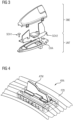
- Fig. 2 shows in cross-section, in a roughly simplified manner, such or another antenna module ATM as an embodiment of the invention, on a vehicle roof FZD.
- An antenna module ATM in Fig. 1 as well as in Fig. 2 is mounted on (here only on the outside) the vehicle roof FZD of a motor vehicle by gluing its underside surface used as adhesive surface KLB (here all around the edge) with an adhesive to the vehicle roof, whereby it is glued on all around, for example.
- antennas ANT1, ANT2, ANT3 of the antenna module ATM and (as or in an extension element VERL1, VERL2, VERL3 each extending downwards, for example) boards of the antenna module ATM with the outer cover AUS of the antenna module ATM are arranged and designed integrated within this (AUS).
- the antenna module ATM in Fig. 1 and 2 has as its outermost cover a hood-shaped, outwardly closed outer cover AUS, which (here with the exception of for contacting (in Fig. 2 ) vehicle-side vehicle connection elements FAE1, FAE2, FAE3 provided connecting elements FAKR1, FAKR2, FAKR3, which can partially protrude into the area inside and/or below the vehicle roof FZD) is completely arranged in an area above (OBE) of a vehicle roof FZD of a motor vehicle.
- AUS vehicle-side vehicle connection elements FAE1, FAE2, FAE3 provided connecting elements FAKR1, FAKR2, FAKR3, which can partially protrude into the area inside and/or below the vehicle roof FZD
- the antenna module ATM in Fig. 1 and 2 is (here with the exception of connecting elements FAKR1, FAKR2, FAKR3) completely mounted above the vehicle roof.
- An antenna module ATM is designed in the state mounted on a vehicle roof FZD (here with the exception of the connecting elements FAKR1, FAKR2, FAKR3) without elements located below (UNT) the vehicle roof FZD (such as circuit board, chassis, antenna, fastening screws).
- Fig. 1 and Fig. 2 all boards VERL1, VERL2, VERL3 of the antenna module ATM are located within the outer cover AUS of the antenna module ATM and above (OBE) of the vehicle roof FZD and here no boards FAE1, FAE2, FAE3 of the antenna module ATM are located outside the outer cover AUS of the antenna module ATM or below (OBE) of the vehicle roof FZD.
- Fig. 1 and Fig. 2 all antennas ANT1, ANT2, ANT3 of the antenna module ATM are located (integrated, e.g.) within the outer cover OUT of the antenna module ATM and above (OBE) of the vehicle roof FZD and here no antennas ANT1, ANT2, ANT3 of the antenna module ATM are located outside the outer cover OUT of the antenna module ATM or below (UNT) of the vehicle roof FZD.
- Antennas ANT1, ANT2, ANT3 can be located e.g.
- Extension elements VERL1, VERL2, VERL3 (on the side of the outer cover AUS closest to the vehicle roof) are provided, each of which can be a circuit board or can have a circuit board (e.g. on their side remote from the vehicle roof).
- One or more extension elements VERL1, VERL2, VERL3 can have a roof contact element DKE1, DKE2, DKE3 on the side of the outer cover AUS near the vehicle roof on its side (VERL1, VERL2, VERL3) near the vehicle roof, which can be contacted with a vehicle roof FZD, e.g. by inserting it into a recess (for one or more roof contact elements DKE1, DKE2, DKE3) in the vehicle roof FZD and/or by turning and/or by placing it on top, in particular galvanically and/or capacitively, and can also serve as a spacer for the vehicle roof FZD if necessary.
- a roof contact element DKE1, DKE2, DKE3 on the side of the outer cover AUS near the vehicle roof on its side (VERL1, VERL2, VERL3) near the vehicle roof, which can be contacted with a vehicle roof FZD, e.g. by inserting it into a recess (for one or more roof contact elements DKE1,
- An extension element VERL1, VERL2, VERL3 can be formed as one piece with the outer cover AUS, or can be connected to the outer cover AUS to form a single part, or can be a separate part from the outer cover AUS and can be inserted into the outer cover AUS.
- a shielding plate SCH for shielding the circuit board and the electronic components arranged on it can be arranged on a circuit board provided on an extension element VERL1, VERL2, VERL3 or in the form of the extension element VERL1, VERL2, VERL3.
- a board of an extension element VERL1, VERL2, VERL3 can each have one or more very simplified VST amplifiers.
- At least one antenna ANT1, ANT2, ANT3 of the antenna module ATM integrated in the outer cover OUT of the antenna module ATM can be, for example, a mobile radio antenna or (GPS) position detection antenna or radio antenna or vehicle-to-vehicle (car-to-car) communication antenna.
- GPS GPS
- car-to-car vehicle-to-vehicle
- a connecting element FAKR1, FAKR2, FAKR3 (e.g. in the form of a Fakra connector) can be provided on each extension element VERL1, VERL2, VERL3 on the vehicle roof side of the outer cover AUS for the galvanic and/or capacitive contact of an antenna ANT1, ANT2, ANT3 integrated with the outer cover AUS with vehicle-side vehicle connection elements FAE1, FAE2, FAE3 for contacting a mobile radio module such as here e.g. (as software and/or hardware) MOBM, position detection module POSM and/or radio module RADM (e.g. as a combined radio,
- the communication module KOM which contains a navigation device and a mobile phone interface device, is located underneath the vehicle roof FZD in the vehicle via cable and/or radio.
Landscapes
- Engineering & Computer Science (AREA)
- Remote Sensing (AREA)
- Support Of Aerials (AREA)
Applications Claiming Priority (3)
| Application Number | Priority Date | Filing Date | Title |
|---|---|---|---|
| DE102015210324.2A DE102015210324A1 (de) | 2015-06-03 | 2015-06-03 | Antennenmodul |
| PCT/EP2016/061851 WO2016193104A1 (fr) | 2015-06-03 | 2016-05-25 | Module d'antenne |
| EP16725517.3A EP3304643A1 (fr) | 2015-06-03 | 2016-05-25 | Module d'antenne |
Related Parent Applications (1)
| Application Number | Title | Priority Date | Filing Date |
|---|---|---|---|
| EP16725517.3A Division EP3304643A1 (fr) | 2015-06-03 | 2016-05-25 | Module d'antenne |
Publications (2)
| Publication Number | Publication Date |
|---|---|
| EP4481945A2 true EP4481945A2 (fr) | 2024-12-25 |
| EP4481945A3 EP4481945A3 (fr) | 2025-04-02 |
Family
ID=56084041
Family Applications (3)
| Application Number | Title | Priority Date | Filing Date |
|---|---|---|---|
| EP22207906.3A Withdrawn EP4178031A1 (fr) | 2015-06-03 | 2016-05-25 | Module d'antenne |
| EP16725517.3A Ceased EP3304643A1 (fr) | 2015-06-03 | 2016-05-25 | Module d'antenne |
| EP24205228.0A Withdrawn EP4481945A3 (fr) | 2015-06-03 | 2016-05-25 | Module d'antenne |
Family Applications Before (2)
| Application Number | Title | Priority Date | Filing Date |
|---|---|---|---|
| EP22207906.3A Withdrawn EP4178031A1 (fr) | 2015-06-03 | 2016-05-25 | Module d'antenne |
| EP16725517.3A Ceased EP3304643A1 (fr) | 2015-06-03 | 2016-05-25 | Module d'antenne |
Country Status (3)
| Country | Link |
|---|---|
| EP (3) | EP4178031A1 (fr) |
| DE (1) | DE102015210324A1 (fr) |
| WO (1) | WO2016193104A1 (fr) |
Families Citing this family (2)
| Publication number | Priority date | Publication date | Assignee | Title |
|---|---|---|---|---|
| KR102688700B1 (ko) * | 2017-02-08 | 2024-07-25 | 얀마 파워 테크놀로지 가부시키가이샤 | 작업 차량용 안테나 유닛, 및 작업 차량 |
| DE102017210514B3 (de) | 2017-06-22 | 2018-08-23 | Audi Ag | Bauteil zum Anpassen einer Impedanz und zum Verstärken eines Signals mit integrierter Antennenstruktur zum Senden und Empfangen von Daten |
Citations (1)
| Publication number | Priority date | Publication date | Assignee | Title |
|---|---|---|---|---|
| DE102012208303B4 (de) | 2012-05-16 | 2014-05-15 | Continental Automotive Gmbh | Antennenmodul mit Sende- und Empfangsantennenelement |
Family Cites Families (12)
| Publication number | Priority date | Publication date | Assignee | Title |
|---|---|---|---|---|
| DE102005052872A1 (de) * | 2005-11-07 | 2007-07-19 | Anselm Dr. Fabig | Verfahren zur Integration von Antennen in Dachzeichen auf Fahrzeugdächern |
| DE202005017773U1 (de) * | 2005-11-11 | 2006-02-02 | Fuba Automotive Gmbh & Co. Kg | Antennenanordnung |
| KR100843150B1 (ko) * | 2007-06-05 | 2008-07-02 | 알에프컨트롤스 주식회사 | 샤크핀식 안테나 |
| DE102007050109B4 (de) * | 2007-10-19 | 2009-08-20 | Wilhelm Sihn Jr. Gmbh & Co. Kg | Fahrzeugantenne und Verfahren zur Herstellung einer Fahrzeugantenne |
| JP4413974B2 (ja) * | 2008-03-12 | 2010-02-10 | 株式会社ビートソニック | 交換用アンテナ |
| JP4798721B2 (ja) * | 2008-05-26 | 2011-10-19 | 株式会社ビートソニック | 車両用ルーフアンテナ |
| KR20100115171A (ko) * | 2009-04-17 | 2010-10-27 | 현대자동차주식회사 | 차량용 통합 안테나 및 그 제작방법 |
| DE102009051605B4 (de) * | 2009-11-02 | 2022-08-18 | Continental Automotive Gmbh | Hochintegrierte Multiband-Finnenantenne für ein Fahrzeug |
| DE102009054009A1 (de) * | 2009-11-19 | 2010-06-24 | Daimler Ag | Anordnung einer Sende- und/oder Empfangseinheit an einem Dachverkleidungsteil eines Kraftwagens |
| JP2012054915A (ja) * | 2010-08-06 | 2012-03-15 | Nippon Soken Inc | アンテナ構造及びダイバーシティアンテナ構造 |
| DE102011016294B4 (de) * | 2011-04-07 | 2013-09-12 | Kathrein-Werke Kg | Dachantenne, insbesondere Kraftfahrzeug-Dachantenne mit zugehöriger Steckverbindungseinrichtung |
| DE102013206519B4 (de) * | 2013-04-12 | 2023-08-17 | Bayerische Motoren Werke Aktiengesellschaft | Antennensystem für ein Fahrzeug und Verfahren zur Herstellung eines solchen Antennensystems |
-
2015
- 2015-06-03 DE DE102015210324.2A patent/DE102015210324A1/de active Pending
-
2016
- 2016-05-25 EP EP22207906.3A patent/EP4178031A1/fr not_active Withdrawn
- 2016-05-25 EP EP16725517.3A patent/EP3304643A1/fr not_active Ceased
- 2016-05-25 WO PCT/EP2016/061851 patent/WO2016193104A1/fr not_active Ceased
- 2016-05-25 EP EP24205228.0A patent/EP4481945A3/fr not_active Withdrawn
Patent Citations (1)
| Publication number | Priority date | Publication date | Assignee | Title |
|---|---|---|---|---|
| DE102012208303B4 (de) | 2012-05-16 | 2014-05-15 | Continental Automotive Gmbh | Antennenmodul mit Sende- und Empfangsantennenelement |
Also Published As
| Publication number | Publication date |
|---|---|
| EP4481945A3 (fr) | 2025-04-02 |
| WO2016193104A1 (fr) | 2016-12-08 |
| DE102015210324A1 (de) | 2016-12-08 |
| EP4178031A1 (fr) | 2023-05-10 |
| EP3304643A1 (fr) | 2018-04-11 |
Similar Documents
| Publication | Publication Date | Title |
|---|---|---|
| EP3192126B1 (fr) | Module d'antenne | |
| DE112016001255B4 (de) | Fahrzeug und Fahrzeugantennengerät | |
| DE102012208303A1 (de) | Antennenmodul mit Sende- und Empfangsantennenelement | |
| DE102019102298A1 (de) | Dachantenne eines Fahrzeuges mit einer Rückfahrkamera | |
| EP1854168B1 (fr) | Antenne en feuille pour un vehicule | |
| EP2466552B1 (fr) | Système d'information à bord doté d'une antenne mobile | |
| EP3304641B1 (fr) | Module antenne pour véhicule automobile | |
| EP4481945A2 (fr) | Module d'antenne | |
| DE102009058181B4 (de) | Träger für Leiterplatte | |
| EP3330733B1 (fr) | Capteur radar pour un véhicule et procédé d'assemblage d'un capteur radar | |
| EP2296967B1 (fr) | Élément interface, élément d'équipement intérieur d'avion et procédé de montage d'un élément d'équipement intérieur d'avion | |
| DE102022206756B4 (de) | Antennenmodul und Kraftfahrzeug | |
| DE10231227B4 (de) | Als Solargenerator ausgebildeter Deckel zum Verschließen einer Öffnung in der Karosserie eines Fahrzeugs | |
| DE102022005059B4 (de) | Antennenmodul und Kraftfahrzeug | |
| AT10686U1 (de) | Mobiles elektrisches gerät für fahrzeuge | |
| EP1905122A1 (fr) | Appareil electronique pour un vehicule comprenant une carte de circuits imprimes a contact direct | |
| DE102005030630B4 (de) | Antenneneinrichtung für mobile Fahrzeuge | |
| DE102013225502A1 (de) | Antennengerät für ein Fahrzeug | |
| EP3513634B1 (fr) | Mise en contact boîtier d'un dispositif de commande | |
| DE102019129630A1 (de) | Antennensystem | |
| DE102013008981B3 (de) | Funkrundsteuerempfänger mit abgesetzter Langwellenantenne | |
| DE102011112327A1 (de) | Kraftfahrzeugvorrichtung mit einem Träger und einer Aufnahme für ein Steuergerät | |
| DE202012003795U1 (de) | Elektronischer Schlüssel | |
| EP1953864A1 (fr) | Antenne, en particulier pour la communication de données par satellite | |
| DE102014219506A1 (de) | Elektrische Bedieneinheit, insbesondere Funkschlüssel für ein Kraftfahrzeug |
Legal Events
| Date | Code | Title | Description |
|---|---|---|---|
| PUAI | Public reference made under article 153(3) epc to a published international application that has entered the european phase |
Free format text: ORIGINAL CODE: 0009012 |
|
| STAA | Information on the status of an ep patent application or granted ep patent |
Free format text: STATUS: THE APPLICATION HAS BEEN PUBLISHED |
|
| AC | Divisional application: reference to earlier application |
Ref document number: 3304643 Country of ref document: EP Kind code of ref document: P |
|
| AK | Designated contracting states |
Kind code of ref document: A2 Designated state(s): AL AT BE BG CH CY CZ DE DK EE ES FI FR GB GR HR HU IE IS IT LI LT LU LV MC MK MT NL NO PL PT RO RS SE SI SK SM TR |
|
| REG | Reference to a national code |
Ref country code: DE Ref legal event code: R079 Free format text: PREVIOUS MAIN CLASS: H01Q0001420000 Ipc: H01Q0001320000 |
|
| PUAL | Search report despatched |
Free format text: ORIGINAL CODE: 0009013 |
|
| AK | Designated contracting states |
Kind code of ref document: A3 Designated state(s): AL AT BE BG CH CY CZ DE DK EE ES FI FR GB GR HR HU IE IS IT LI LT LU LV MC MK MT NL NO PL PT RO RS SE SI SK SM TR |
|
| RIC1 | Information provided on ipc code assigned before grant |
Ipc: H01Q 1/42 20060101ALI20250226BHEP Ipc: H01Q 1/12 20060101ALI20250226BHEP Ipc: H01Q 1/32 20060101AFI20250226BHEP |
|
| STAA | Information on the status of an ep patent application or granted ep patent |
Free format text: STATUS: REQUEST FOR EXAMINATION WAS MADE |
|
| 17P | Request for examination filed |
Effective date: 20251002 |
|
| RAP3 | Party data changed (applicant data changed or rights of an application transferred) |
Owner name: AUMOVIO GERMANY GMBH |
|
| STAA | Information on the status of an ep patent application or granted ep patent |
Free format text: STATUS: THE APPLICATION IS DEEMED TO BE WITHDRAWN |
|
| 18D | Application deemed to be withdrawn |
Effective date: 20251003 |