EP4488465A1 - Panneau pour l'aménagement intérieur à sec - Google Patents
Panneau pour l'aménagement intérieur à sec Download PDFInfo
- Publication number
- EP4488465A1 EP4488465A1 EP24185653.3A EP24185653A EP4488465A1 EP 4488465 A1 EP4488465 A1 EP 4488465A1 EP 24185653 A EP24185653 A EP 24185653A EP 4488465 A1 EP4488465 A1 EP 4488465A1
- Authority
- EP
- European Patent Office
- Prior art keywords
- panel
- plate
- profile
- moisture
- floor
- Prior art date
- Legal status (The legal status is an assumption and is not a legal conclusion. Google has not performed a legal analysis and makes no representation as to the accuracy of the status listed.)
- Granted
Links
Images






Classifications
-
- E—FIXED CONSTRUCTIONS
- E04—BUILDING
- E04B—GENERAL BUILDING CONSTRUCTIONS; WALLS, e.g. PARTITIONS; ROOFS; FLOORS; CEILINGS; INSULATION OR OTHER PROTECTION OF BUILDINGS
- E04B2/00—Walls, e.g. partitions, for buildings; Wall construction with regard to insulation; Connections specially adapted to walls
- E04B2/74—Removable non-load-bearing partitions; Partitions with a free upper edge
- E04B2/7407—Removable non-load-bearing partitions; Partitions with a free upper edge assembled using frames with infill panels or coverings only; made-up of panels and a support structure incorporating posts
- E04B2/7448—Removable non-load-bearing partitions; Partitions with a free upper edge assembled using frames with infill panels or coverings only; made-up of panels and a support structure incorporating posts with separate framed panels without intermediary posts, extending from floor to ceiling
-
- E—FIXED CONSTRUCTIONS
- E04—BUILDING
- E04B—GENERAL BUILDING CONSTRUCTIONS; WALLS, e.g. PARTITIONS; ROOFS; FLOORS; CEILINGS; INSULATION OR OTHER PROTECTION OF BUILDINGS
- E04B2/00—Walls, e.g. partitions, for buildings; Wall construction with regard to insulation; Connections specially adapted to walls
- E04B2/72—Non-load-bearing walls of elements of relatively thin form with respect to the thickness of the wall
-
- E—FIXED CONSTRUCTIONS
- E04—BUILDING
- E04B—GENERAL BUILDING CONSTRUCTIONS; WALLS, e.g. PARTITIONS; ROOFS; FLOORS; CEILINGS; INSULATION OR OTHER PROTECTION OF BUILDINGS
- E04B1/00—Constructions in general; Structures which are not restricted either to walls, e.g. partitions, or floors or ceilings or roofs
- E04B1/02—Structures consisting primarily of load-supporting, block-shaped, or slab-shaped elements
- E04B1/08—Structures consisting primarily of load-supporting, block-shaped, or slab-shaped elements the elements consisting of metal
-
- E—FIXED CONSTRUCTIONS
- E04—BUILDING
- E04B—GENERAL BUILDING CONSTRUCTIONS; WALLS, e.g. PARTITIONS; ROOFS; FLOORS; CEILINGS; INSULATION OR OTHER PROTECTION OF BUILDINGS
- E04B1/00—Constructions in general; Structures which are not restricted either to walls, e.g. partitions, or floors or ceilings or roofs
- E04B1/02—Structures consisting primarily of load-supporting, block-shaped, or slab-shaped elements
- E04B1/14—Structures consisting primarily of load-supporting, block-shaped, or slab-shaped elements the elements being composed of two or more materials
-
- E—FIXED CONSTRUCTIONS
- E04—BUILDING
- E04B—GENERAL BUILDING CONSTRUCTIONS; WALLS, e.g. PARTITIONS; ROOFS; FLOORS; CEILINGS; INSULATION OR OTHER PROTECTION OF BUILDINGS
- E04B1/00—Constructions in general; Structures which are not restricted either to walls, e.g. partitions, or floors or ceilings or roofs
- E04B1/38—Connections for building structures in general
-
- E—FIXED CONSTRUCTIONS
- E04—BUILDING
- E04B—GENERAL BUILDING CONSTRUCTIONS; WALLS, e.g. PARTITIONS; ROOFS; FLOORS; CEILINGS; INSULATION OR OTHER PROTECTION OF BUILDINGS
- E04B2/00—Walls, e.g. partitions, for buildings; Wall construction with regard to insulation; Connections specially adapted to walls
- E04B2/02—Walls, e.g. partitions, for buildings; Wall construction with regard to insulation; Connections specially adapted to walls built-up from layers of building elements
- E04B2/04—Walls having neither cavities between, nor in, the solid elements
-
- E—FIXED CONSTRUCTIONS
- E04—BUILDING
- E04B—GENERAL BUILDING CONSTRUCTIONS; WALLS, e.g. PARTITIONS; ROOFS; FLOORS; CEILINGS; INSULATION OR OTHER PROTECTION OF BUILDINGS
- E04B2/00—Walls, e.g. partitions, for buildings; Wall construction with regard to insulation; Connections specially adapted to walls
- E04B2/02—Walls, e.g. partitions, for buildings; Wall construction with regard to insulation; Connections specially adapted to walls built-up from layers of building elements
- E04B2/04—Walls having neither cavities between, nor in, the solid elements
- E04B2/06—Walls having neither cavities between, nor in, the solid elements using elements having specially-designed means for stabilising the position
- E04B2/08—Walls having neither cavities between, nor in, the solid elements using elements having specially-designed means for stabilising the position by interlocking of projections or inserts with indentations, e.g. of tongues, grooves, dovetails
-
- E—FIXED CONSTRUCTIONS
- E04—BUILDING
- E04B—GENERAL BUILDING CONSTRUCTIONS; WALLS, e.g. PARTITIONS; ROOFS; FLOORS; CEILINGS; INSULATION OR OTHER PROTECTION OF BUILDINGS
- E04B2/00—Walls, e.g. partitions, for buildings; Wall construction with regard to insulation; Connections specially adapted to walls
- E04B2/74—Removable non-load-bearing partitions; Partitions with a free upper edge
- E04B2/82—Removable non-load-bearing partitions; Partitions with a free upper edge characterised by the manner in which edges are connected to the building; Means therefor; Special details of easily-removable partitions as far as related to the connection with other parts of the building
- E04B2/825—Removable non-load-bearing partitions; Partitions with a free upper edge characterised by the manner in which edges are connected to the building; Means therefor; Special details of easily-removable partitions as far as related to the connection with other parts of the building the connection between the floor and the ceiling being achieved without any restraining forces acting in the plane of the partition
-
- E—FIXED CONSTRUCTIONS
- E04—BUILDING
- E04B—GENERAL BUILDING CONSTRUCTIONS; WALLS, e.g. PARTITIONS; ROOFS; FLOORS; CEILINGS; INSULATION OR OTHER PROTECTION OF BUILDINGS
- E04B2/00—Walls, e.g. partitions, for buildings; Wall construction with regard to insulation; Connections specially adapted to walls
- E04B2/88—Curtain walls
- E04B2/90—Curtain walls comprising panels directly attached to the structure
- E04B2/92—Sandwich-type panels
-
- E—FIXED CONSTRUCTIONS
- E04—BUILDING
- E04C—STRUCTURAL ELEMENTS; BUILDING MATERIALS
- E04C2/00—Building elements of relatively thin form for the construction of parts of buildings, e.g. sheet materials, slabs, or panels
- E04C2/02—Building elements of relatively thin form for the construction of parts of buildings, e.g. sheet materials, slabs, or panels characterised by specified materials
- E04C2/26—Building elements of relatively thin form for the construction of parts of buildings, e.g. sheet materials, slabs, or panels characterised by specified materials composed of materials covered by two or more of groups E04C2/04, E04C2/08, E04C2/10 or of materials covered by one of these groups with a material not specified in one of the groups
- E04C2/284—Building elements of relatively thin form for the construction of parts of buildings, e.g. sheet materials, slabs, or panels characterised by specified materials composed of materials covered by two or more of groups E04C2/04, E04C2/08, E04C2/10 or of materials covered by one of these groups with a material not specified in one of the groups at least one of the materials being insulating
- E04C2/292—Building elements of relatively thin form for the construction of parts of buildings, e.g. sheet materials, slabs, or panels characterised by specified materials composed of materials covered by two or more of groups E04C2/04, E04C2/08, E04C2/10 or of materials covered by one of these groups with a material not specified in one of the groups at least one of the materials being insulating composed of insulating material and sheet metal
-
- E—FIXED CONSTRUCTIONS
- E04—BUILDING
- E04C—STRUCTURAL ELEMENTS; BUILDING MATERIALS
- E04C2/00—Building elements of relatively thin form for the construction of parts of buildings, e.g. sheet materials, slabs, or panels
- E04C2/30—Building elements of relatively thin form for the construction of parts of buildings, e.g. sheet materials, slabs, or panels characterised by the shape or structure
- E04C2/40—Building elements of relatively thin form for the construction of parts of buildings, e.g. sheet materials, slabs, or panels characterised by the shape or structure composed of a number of smaller components rigidly or movably connected together, e.g. interlocking, hingedly connected of particular shape, e.g. not rectangular of variable shape or size, e.g. flexible or telescopic panels
-
- E—FIXED CONSTRUCTIONS
- E04—BUILDING
- E04B—GENERAL BUILDING CONSTRUCTIONS; WALLS, e.g. PARTITIONS; ROOFS; FLOORS; CEILINGS; INSULATION OR OTHER PROTECTION OF BUILDINGS
- E04B2/00—Walls, e.g. partitions, for buildings; Wall construction with regard to insulation; Connections specially adapted to walls
- E04B2/74—Removable non-load-bearing partitions; Partitions with a free upper edge
-
- E—FIXED CONSTRUCTIONS
- E04—BUILDING
- E04B—GENERAL BUILDING CONSTRUCTIONS; WALLS, e.g. PARTITIONS; ROOFS; FLOORS; CEILINGS; INSULATION OR OTHER PROTECTION OF BUILDINGS
- E04B2103/00—Material constitution of slabs, sheets or the like
- E04B2103/04—Material constitution of slabs, sheets or the like of plastics, fibrous material or wood
-
- E—FIXED CONSTRUCTIONS
- E04—BUILDING
- E04B—GENERAL BUILDING CONSTRUCTIONS; WALLS, e.g. PARTITIONS; ROOFS; FLOORS; CEILINGS; INSULATION OR OTHER PROTECTION OF BUILDINGS
- E04B2103/00—Material constitution of slabs, sheets or the like
- E04B2103/06—Material constitution of slabs, sheets or the like of metal
Definitions
- the invention relates to a panel for dry interior construction, which has a sandwich-like structure, according to claim 1, and to a panel system in which these panels are used.
- the work required is time-consuming and therefore blocks the construction site for a long time. It also creates waste that can cause problems on the construction site, such as small pieces of steel or the dust that is generated when cutting the plasterboard. Although the fire-retardant properties are satisfactory, the acoustic insulation is weak and the space required is too small compared to the insulation effect.
- the CN209990012U reveals a system of fire-retardant gypsum boards in which the gypsum walls are bonded to U-shaped metal plates on one side. These gypsum composite boards have fire-retardant properties, but require a relatively large amount of installation space and are susceptible to moisture penetration.
- the DE202017104561U1 discloses a partition wall system, especially for interior spaces in office buildings, exhibition and residential buildings with a load-bearing skeleton. Partition walls according to this publication have a soundproofing function, but also require a lot of installation space and are susceptible to moisture penetration.
- a panel for dry interior construction which has the features specified in the characterizing part of claim 1.
- a classic drywall panel preferably made of gypsum fiber, is used as the panel core and is provided on each of its sides with a moisture-resistant, preferably metallic, cover panel, which is optionally coated, painted or foiled, with a filling in between already glued in the factory and preferably manufactured to fit precisely, or cut to fit precisely on site.
- This dry interior panel has a predetermined underside.
- a groove is provided on this underside of the panel to accommodate a floor profile that is attached to the floor and positions the panel. If the dry interior panel is intended to abut another dry interior panel along a vertical joint, it also has a groove formed on this side surface, which does not necessarily have the same geometric dimensions as the groove on the underside of the panel.
- the panel is finally fixed using a ceiling profile and, if necessary, a side profile.
- the panel for dry interior construction has a filling of moisture-resistant material at least in the lower area (the area closest to the floor) where such access is feared (this can therefore also include the entire panel), and the joints that the panel has in the floor area, regardless of whether they run horizontally or vertically, are preferably provided with a hydromechanically insulating mass so that there is no risk of rising moisture.
- a second sealing level can, but does not have to, be installed between the hydromechanically insulating mass and the panel core using sealing tape and/or sealing profile.
- a gypsum fibreboard is used as the core of the board, it is preferably glued to the cover panels, but it is also possible, for example, to use the cover panels as permanent formwork and pour in the filling and allow it to harden, which also creates a permanent connection with the cover panels.
- the individual wall panels can be made of different materials and can be combined with each other if the thickness is the same, so that glass in a sandwich construction i.e. made of VSG (laminated safety glass) or ESG (tempered safety glass) with a groove to be designed according to the application, i.e. on 3 sides or only on the bottom side, in combination with panels according to the invention for dry interior construction.
- VSG laminate safety glass
- ESG tempered safety glass
- the big advantage over the state of the art, even in the version without seals, is that the formwork on both sides with cover panels saves a lot of installation space compared to conventional systems and yet surprisingly significant improvements in sound insulation can be achieved.
- a noticeable reduction in the thickness of the partition wall can be achieved compared to the state of the art, which noticeably increases the usable area of the apartment or office, or the area to be built on (requirement for floor sealing per apartment) can be minimized.
- Another major advantage over the state of the art in the preferred embodiment of the panel for dry interior construction is the possibility of shielding it hydromechanically and thus preventing in particular the penetration of water and, as a result, the swelling of classic drywall panels.
- the Fig. 1a shows, in a purely schematic manner, a vertical section through a panel 1 according to the invention for dry interior construction, which in the embodiment shown is equipped for use in a wet room.
- the panel 1 consists of a filling 2 (the panel core) and is provided on both sides with moisture-resistant cover panels 3, 4.
- the cover panels 3, 4 can, but do not have to, have the same mechanical and geometric properties.
- the cover panels 3, 4 can consist of a wide variety of moisture-resistant materials, such as plastic and metal.
- the cover panels 3, 4 are preferably made of metallic material in order to achieve fire-retardant properties in addition to moisture resistance. Steel or aluminum in different material thicknesses, preferably between 0.4 mm and 1 mm, is particularly preferred.
- the plate 1 has a groove 6 on its underside 5, which is suitable for receiving a web 7 of a floor profile 8.
- Fig. 1 obvious features: In the lower area, a moisture-resistant filling 2' is attached instead of the panel core 2. Preferably, at least in this area, between the filling 2' and the panel core 2 in the area between the cover panels 3, 4, a further, internal seal 9 is provided. In the embodiment shown, this internal seal 9 is shown and formed above the moisture-resistant filling 2'. Furthermore, the floor profile 8 is not attached directly to the floor 11, but via a moisture-repellent (hydrophobic) and moisture-insulating intermediate layer 10, which is preferably an easy-to-apply hydrophobic swelling paste, in order to avoid direct contact with the floor as far as possible. This also largely prevents the passage of moisture through capillaries.
- a moisture-repellent (hydrophobic) and moisture-insulating intermediate layer 10 which is preferably an easy-to-apply hydrophobic swelling paste, in order to avoid direct contact with the floor as far as possible. This also largely prevents the passage of moisture through capillaries.
- Fig. 1 the groove 6 is shown significantly deeper than the height of the web 7, but there does not have to be that much of an overhang. It is important to avoid the front of the web 7 hitting the bottom of the groove 6, as this can lead to mechanical problems. Transferring the weight of the plate 1 via the metal cover plates 3, 4 to the bottom profile 8 is generally preferred. The front of the web 7 and the bottom of the groove 6 should therefore touch at most when installed.
- the inner seal 9 preferably consists of hydrophobic material such as rubber, silicone rubber, plastic, etc. and has a certain elasticity which is used during insertion to create a force-fitting connection and thus a sealing contact against the cover plates 3, 4, the filling 2 as well as the base profile 8 and/or the filling 2'.
- the filling 2 is connected to the cover plates 3, 4 using an adhesive, but as already explained, it can also be obtained by pouring it into the formwork.
- the moisture-resistant filling 2' can also be glued to the cover plates 3, 4, or it can be foamed or poured in or held in place by elastic pre-stressing, which ensures that the weight of the plate 1 is transferred to the floor profile 8 via the cover plates 3, 4.
- the Fig. 1b shows a version of Plate 1 for dry interior construction analogous to Fig. 1a .
- the inner seal 9 is replaced by the inner seal 9a.
- the inner seal 9a is directly connected to the filling 2 inside the panel and forms two webs running downwards, each of which encloses fillings 2 ⁇ between itself and the cover panels 3, 4, whereby there is no filling 2 ⁇ between the webs and the groove 6 thus extends vertically upwards from the base profile 8 to the lower edge of the inner seal 9a.
- the Fig. 2a shows an example of a horizontal section through a vertical joint between two panels 1 for dry interior construction in the area of their side edges 24, analogous to Fig. 1a .
- a butt joint profile 18 made of permanently elastic plastic or rubber is used to ensure a flat (aligned) connection of the panels 1 to one another.
- the length of the butt joint profile 18 in the horizontal direction is preferably somewhat shorter than the sum L of the depths of the two grooves in order to reliably avoid longitudinal stresses.
- the vertical extension (normal to the image plane) of the butt joint profile 18 preferably extends from the floor profile 8 (see Fig. 1 ) to the upper edge of the plates 1, whereby a division into smaller pieces is of course also possible. Whether and in what form the drawn "barbs" are provided is easy to determine for the expert with knowledge of the invention and the respective field of application. The use of the materials mentioned ensures that the plates can be easily separated in the event of a conversion or replacement.
- inner seal 9 is also provided, although this is a particularly preferred embodiment, but is only necessary in special cases or recommended, for example, to protect the neighbouring panels in the event of water entering one of the panels, so that only the panels damaged by the water need to be replaced. It is therefore also possible, for example, not to provide these seals 9, even if seals are present in the base area of the panels see Fig. 1a or 1b).
- the Fig. 2b shows an alternative horizontal section through a vertical joint between two panels 1 for dry interior construction in the area of their side edges 24, analogous to Fig. 1b .
- the general statements in Fig. 2a were also taken for Fig. 2b Validity.
- a different joint profile 18 can also be used.
- the length of the butt joint profile 18 in the horizontal direction should preferably be somewhat shorter than the sum L of the depths of the two grooves.
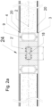
- the Fig. 3a to d shows an embodiment of a soil profile 8 in a longitudinal ( Fig. 3a ) and two cross sections ( Fig. 3b & c ) and a perspective view ( Fig. 3d ).
- the respective sections are marked with AA, BB and CC.
- the height H of the web 7 is also indicated.
- the installation on the subfloor or screed is carried out, for example, by screwing or gluing or using nails. Construction tolerances can be compensated for using supports made of various pressure-resistant materials.
- the seal against the floor is preferably made using swelling paste 10 (see Fig. 1 ).
- the dead weight of the panels 1 is statically transferred to the floor profile 8 via the cover panels 3, 4.
- the width of the floor profile 8 preferably corresponds to the thickness of the associated plate(s) 1.
- a slight overhang of the floor profile 8 can be mechanically advantageous, here a balance between appearance and safety is possible.
- the holes for the fastening elements are shown without their own reference numerals, the height H of the web 7 above the upper, horizontal surface of the floor profile 8 is, as already Fig. 1 described, to be coordinated with the depth of the groove 6 of the panels 1 used in order not to divert vertical forces via the web 7.
- the cross-sectional shape of the web 7 can vary within wide limits as long as guidance and positioning in a horizontal direction transverse to the longitudinal axis of the floor profile 8 is achieved.
- the slightly undercut shape shown represents a particularly favorable embodiment, since a particularly favorable mounting of the panel 1 can be achieved by slightly elastic deformation of the filling 2 or 2'.
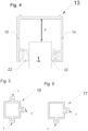
- the Fig. 4 shows a ceiling profile 13 that can be used for the installation of the panel 1 according to the invention.
- the two legs 14, 15 of the profile 13 are significantly longer than the recess of the panel 1, which is shown schematically in dotted lines and protrudes into the ceiling profile 13.
- the projection D is noticeably higher than the height H (see Fig. 3 ) of the web 7 of the floor profile 8. This makes it possible to thread the panel 1 into the ceiling profile 13 from below until its upper edge abuts the inside of the bottom of the ceiling profile 13, then to swing it over the floor profile 8 and let its groove 6 slide over the web 7 of the floor profile.
- This projection D also makes it possible to accommodate structural tolerances so that no statically effective forces are transferred vertically into the panel 1.
- various inwardly projecting webs (without reference symbols) are provided, which serve to accommodate rubber or plastic profiles 22 or permanently elastic sealing compounds, which are indicated with faint lines. These can be the same on both sides, or as in Fig. 4 shown, can be of varying degrees.
- the panel 1 is held in place by these rubber or plastic profiles 22 or permanently elastic sealing compounds without coming into contact with the ceiling profile 13, whereby structure-borne noise is not transmitted or is transmitted only in a strongly dampened manner.
- these ceiling profiles can be filled more or less densely as required, for example using foam strips (compression strips or other swelling filling materials).
- the ceiling profile 13 is attached to the ceiling either directly or, like the floor profile 8 on the floor, via an insulation zone, for example by screwing or gluing or by means of shot nails.
- Figs. 5 and 6 show horizontal sections through a connection profile to be laid vertically between two (17) or three (16) panels 1 for a T-joint 16 or for a corner 17, in which webs 7 are designed analogously to the web 7 of the floor profile 8, which, despite the different arrangement and possibly different dimensions, have been given the same reference number to clarify the analogy.
- These profiles 16, 17 can either be glued to the panels 1 or simply plugged in.
- Fig. 7a or b shows in section normal to the longitudinal extension examples of a usually band-shaped butt joint element 18, which can be inserted into the vertical grooves of adjacent panels 1 and holds the panels 1 butt to butt with the respective edges of the groove, see Fig. 2a or b.
- Fig. 7a one in Fig. 2a used butt joint element 18
- Fig. 7b one in Fig. 2b used butt joint element 18.
- the width L1 the element width of the butt element 18, is not greater than the combined depth of the two grooves of the adjacent plates 1.
- the shape and number of the Fig. 7a The barbs shown can be varied within wide limits and, for example, replaced by round shapes (similar to O-rings in grooves); all kinds of combinations are possible.
- the Fig. 8 shows an example of a finishing profile 19 of a wall finish. This can be glued or simply plugged in.
- a design of the web as in the butt joint element 18 in Fig. 7 i.e. with or without barbs, is also possible. Plastic with good mechanical properties or aluminum is preferred as the material.
- the Fig. 9 shows an example of a 2-part wall connection profile 14, 21 with the clearance L to accommodate structural tolerances.
- seals 22 are provided, which of course can also be dispensed with (workshops, storage rooms, etc.) and do not have to be of the same type.
- the leg 14 is first attached to the wall/ceiling, then the panel 1 is placed and finally the click profile 21 is clipped on.
- these wall connection profiles can be filled more or less tightly as required, for example using foam tapes (compression tapes or other swelling filling materials).
- a ceiling profile 13 Fig. 4
- the Fig. 10 shows an example of a door frame profile 23 for installation in a wall consisting of panels 1 in a horizontal section.
- the door can be room-high, or provided with a skylight, or with panel(s) 1 above the lintel (in which case the door frame is constructed from such profiles, cut at a mitre).
- seals 22 are provided to enclose panel 1, panel 1 is shown here as a typical panel for a dry area only with filling 2, thus without an inner seal 9, 9a, up to the side edge 24 and without a groove 6 (which can of course be provided), in order to visually demonstrate this variant, which can of course be used anywhere and on all edges.
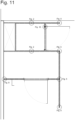
- Fig. 11 shows a schematic top view of an example of a section of a floor plan, showing where the parts and elements shown in the individual figures can be inserted.
- a double-sided adhesive tape can be used to bond the gypsum fiberboard to the cover panels.
- the S-4710 MF from ATP is an example.
- Plates made of moisture-resistant material, such as plastics or metals can be used as cover plates 3, 4. Due to the flame-retardant effect, versions of the plate 1 according to the invention with cover plates 3, 4 made of aluminum, including various aluminum alloys, in particular aluminum-manganese alloys, or cover plates 3, 4 made of steel are particularly preferred. With knowledge of the invention and the requirements for the finished plate 1 and the cover plates 3, 4, the person with specialist training in the field of dry interior construction can easily make his or her choice.
- swelling pastes or sealing compounds based on polyurethane with a low proportion of free monomeric diisocyanates such as Sikaflex ® 11FC Purform ®
- Compounds based on silicones, polysulfides or hot melt can also be used.
- a two-component polyurethane sealant such as that used in insulating glass, can be used as a moisture-resistant material for filling 2'.
- POLIVER GP-AC from FENZI is recommended.
- the profiles 13, 14, 15, 19, 21 can, independently of one another, consist of aluminum, various aluminum alloys, in particular aluminum-manganese alloys, or plastic.
- the impact element 18 can be made of aluminum, rubber, wood or plastic, for example.
- the inner seal 9, 9a can consist, for example, of butyl-aluminium composite material or other silicones or other waterproof materials suitable as seal 9, 9a. Suitable sealants are known to the specialist.
- classic drywall board for example in connection with filling 2, means a board that is suitable for drywall construction.
- the specialist usually understands this to mean gypsum fiberboard, wood fiberboard, clay building board or similar.
- the main advantage of the invention is to provide panels 1 for dry interior construction that can be installed quickly, easily and without causing unnecessary dirt on construction sites. These panels 1 can be easily threaded into pre-installed floor profiles 8 and fixed, for example, using ceiling profiles 13. Due to the special sandwich construction and the possibility of additionally insulating the connecting profiles, good soundproofing properties can be achieved in a very compact installation space, which in the prior art would require at least two classic drywalls installed in parallel with insulation material in between.
- these properties of the panel 1 or the panel system can be improved by attaching fireproof cover panels 3, 4, which are preferably made of metal, and in addition a very good flame-retardant effect of the resulting wall can be achieved.
- One reason for the improvement in the flame-retardant effect is the extensive omission of flammable materials such as insulation wool, which can be achieved through the special construction.
- the properties of the panel 1 can be further improved by providing a moisture-resistant filling 2 ⁇ and, if necessary, an internal seal 9, 9a.
- a moisture-resistant filling 2 ⁇ and, if necessary, an internal seal 9, 9a In this way, the sides provided with the filling 2 ⁇ or the internal seal 9, 9a can also be sealed against the ingress of liquid. If this filling 2 ⁇ or internal seal 9, 9a is used on all If the cover plates 3, 4 are made of metallic materials, the resulting plate 1 is optimally sealed against the ingress of liquids and is very suitable for use in wet rooms, and also has flame-retardant properties.
Landscapes
- Engineering & Computer Science (AREA)
- Architecture (AREA)
- Civil Engineering (AREA)
- Structural Engineering (AREA)
- Physics & Mathematics (AREA)
- Electromagnetism (AREA)
- Building Environments (AREA)
Priority Applications (1)
| Application Number | Priority Date | Filing Date | Title |
|---|---|---|---|
| HRP20260310TT HRP20260310T1 (hr) | 2023-07-07 | 2024-07-01 | Panel za suhu unutarnju ugradnju |
Applications Claiming Priority (1)
| Application Number | Priority Date | Filing Date | Title |
|---|---|---|---|
| ATA50544/2023A AT527214B1 (de) | 2023-07-07 | 2023-07-07 | Platte für den Trockenausbau |
Publications (3)
| Publication Number | Publication Date |
|---|---|
| EP4488465A1 true EP4488465A1 (fr) | 2025-01-08 |
| EP4488465B1 EP4488465B1 (fr) | 2025-12-10 |
| EP4488465C0 EP4488465C0 (fr) | 2025-12-10 |
Family
ID=91759597
Family Applications (1)
| Application Number | Title | Priority Date | Filing Date |
|---|---|---|---|
| EP24185653.3A Active EP4488465B1 (fr) | 2023-07-07 | 2024-07-01 | Panneau pour l'aménagement intérieur à sec |
Country Status (4)
| Country | Link |
|---|---|
| EP (1) | EP4488465B1 (fr) |
| AT (1) | AT527214B1 (fr) |
| HR (1) | HRP20260310T1 (fr) |
| PL (1) | PL4488465T3 (fr) |
Citations (7)
| Publication number | Priority date | Publication date | Assignee | Title |
|---|---|---|---|---|
| CH587984A5 (en) * | 1976-11-15 | 1977-05-31 | Boschetti Serramenteria Sa | Noise and fire insulating partition wall - has edge support profile and cavity filled with incombustible material |
| US5010702A (en) * | 1989-04-03 | 1991-04-30 | Daw Technologies, Inc. | Modular wall system |
| DE19960535A1 (de) | 1999-12-15 | 2001-06-21 | Lindner Ag | Trennwandaufbau |
| DE202017104561U1 (de) | 2017-07-31 | 2017-09-26 | Liko-S, A.S. | Trennwand für Innenräume |
| CN108468405A (zh) * | 2018-04-04 | 2018-08-31 | 山东万事达建筑钢品股份有限公司 | 一种新型净化板连接配件 |
| CN209990012U (zh) | 2019-03-11 | 2020-01-24 | 浙江亚厦装饰股份有限公司 | 一种多功能组合墙板结构 |
| JP2020026674A (ja) | 2018-08-10 | 2020-02-20 | 日鉄鋼板株式会社 | 間仕切壁 |
Family Cites Families (4)
| Publication number | Priority date | Publication date | Assignee | Title |
|---|---|---|---|---|
| GB442254A (en) * | 1935-02-11 | 1936-02-05 | Guy Felix Kotrbaty | Improvements in or relating to composite wall members and method of making the same, and to wall constructions made therefrom |
| DE9111122U1 (de) * | 1991-09-07 | 1991-11-21 | Hausverwaltung Friedrich GmbH, 5559 Kenn | Schnellbau-Trennwand |
| JPH1122077A (ja) * | 1997-06-30 | 1999-01-26 | Sekisui Plastics Co Ltd | 組立式間仕切り壁構造とその構築方法 |
| JP2006028835A (ja) * | 2004-07-14 | 2006-02-02 | Toto Ltd | ユニットルームの壁パネル、その接続構造及び接続材 |
-
2023
- 2023-07-07 AT ATA50544/2023A patent/AT527214B1/de active
-
2024
- 2024-07-01 EP EP24185653.3A patent/EP4488465B1/fr active Active
- 2024-07-01 PL PL24185653.3T patent/PL4488465T3/pl unknown
- 2024-07-01 HR HRP20260310TT patent/HRP20260310T1/hr unknown
Patent Citations (7)
| Publication number | Priority date | Publication date | Assignee | Title |
|---|---|---|---|---|
| CH587984A5 (en) * | 1976-11-15 | 1977-05-31 | Boschetti Serramenteria Sa | Noise and fire insulating partition wall - has edge support profile and cavity filled with incombustible material |
| US5010702A (en) * | 1989-04-03 | 1991-04-30 | Daw Technologies, Inc. | Modular wall system |
| DE19960535A1 (de) | 1999-12-15 | 2001-06-21 | Lindner Ag | Trennwandaufbau |
| DE202017104561U1 (de) | 2017-07-31 | 2017-09-26 | Liko-S, A.S. | Trennwand für Innenräume |
| CN108468405A (zh) * | 2018-04-04 | 2018-08-31 | 山东万事达建筑钢品股份有限公司 | 一种新型净化板连接配件 |
| JP2020026674A (ja) | 2018-08-10 | 2020-02-20 | 日鉄鋼板株式会社 | 間仕切壁 |
| CN209990012U (zh) | 2019-03-11 | 2020-01-24 | 浙江亚厦装饰股份有限公司 | 一种多功能组合墙板结构 |
Also Published As
| Publication number | Publication date |
|---|---|
| HRP20260310T1 (hr) | 2026-04-24 |
| AT527214B1 (de) | 2024-12-15 |
| EP4488465B1 (fr) | 2025-12-10 |
| AT527214A4 (de) | 2024-12-15 |
| PL4488465T3 (pl) | 2026-04-27 |
| EP4488465C0 (fr) | 2025-12-10 |
Similar Documents
| Publication | Publication Date | Title |
|---|---|---|
| DE102012224201A1 (de) | Vakuumisolierende Fassadenplatte mit verbesserter Handhabbarkeit | |
| EP0560013B1 (fr) | Panneau en bois | |
| EP3060725B1 (fr) | Composite anti-effraction et structure de mur porteur, de toit ou de plafond | |
| DE2636531A1 (de) | Fertigbauelement | |
| DE29518865U1 (de) | Plattenförmiges Dämmelement aus Mineralwolle | |
| AT403936B (de) | Wandelement | |
| DE3444815C2 (fr) | ||
| EP4488465B1 (fr) | Panneau pour l'aménagement intérieur à sec | |
| EP2820197B1 (fr) | Élément d'isolation | |
| DE9302447U1 (de) | Holzbautafel | |
| EP2374959A1 (fr) | Elément en sandwich pour la construction de bâtiment, procédé de de réalisation d'un tel élément en sandwich ainsi que l'utilisation d'un panneau isolant | |
| EP3971361B1 (fr) | Panneau mural en argile | |
| AT398229B (de) | Schachteinrichtung mit einem nach unten offenen aufnahmeschacht zur aufnahme eines rolladens, einer jalousie oder dergleichen | |
| DE7625460U1 (de) | Fertigbauelement | |
| AT409986B (de) | Vorsatzschale | |
| DE3544672A1 (de) | Wand- oder deckenverkleidung | |
| EP4343099B1 (fr) | Support d'un élément en forme de plaque | |
| EP3983619B1 (fr) | Bâtiment avec au moins un mur en bois avec un socle attenant | |
| AT500597B1 (de) | Bauwerksmodul | |
| EP0826844B1 (fr) | Colonne en bois par collage pour méthode de construction d'une ossature en bois | |
| DE3425619A1 (de) | Leichtbau-wand aus rechteckigen gipswandbauplatten und verfahren zum aufbau der wand | |
| EP1574632B1 (fr) | Mur en construction sèche | |
| AT505324A1 (de) | Holzbauelement und daraus gebildetes wandelement | |
| DE9419795U1 (de) | Wandkonstruktion für und Bauwerk in Ständerbauweise | |
| DE202023104429U1 (de) | Brandabschottung für Leitungen in Gebäuden |
Legal Events
| Date | Code | Title | Description |
|---|---|---|---|
| REG | Reference to a national code |
Ref country code: HR Ref legal event code: TUEP Ref document number: P20260310T Country of ref document: HR |
|
| PUAI | Public reference made under article 153(3) epc to a published international application that has entered the european phase |
Free format text: ORIGINAL CODE: 0009012 |
|
| STAA | Information on the status of an ep patent application or granted ep patent |
Free format text: STATUS: THE APPLICATION HAS BEEN PUBLISHED |
|
| AK | Designated contracting states |
Kind code of ref document: A1 Designated state(s): AL AT BE BG CH CY CZ DE DK EE ES FI FR GB GR HR HU IE IS IT LI LT LU LV MC ME MK MT NL NO PL PT RO RS SE SI SK SM TR |
|
| STAA | Information on the status of an ep patent application or granted ep patent |
Free format text: STATUS: REQUEST FOR EXAMINATION WAS MADE |
|
| 17P | Request for examination filed |
Effective date: 20250526 |
|
| RAV | Requested validation state of the european patent: fee paid |
Extension state: GE Effective date: 20250526 |
|
| RAX | Requested extension states of the european patent have changed |
Extension state: BA Payment date: 20250526 |
|
| GRAP | Despatch of communication of intention to grant a patent |
Free format text: ORIGINAL CODE: EPIDOSNIGR1 |
|
| STAA | Information on the status of an ep patent application or granted ep patent |
Free format text: STATUS: GRANT OF PATENT IS INTENDED |
|
| RIC1 | Information provided on ipc code assigned before grant |
Ipc: E04B 2/74 20060101AFI20250910BHEP Ipc: E04B 2/82 20060101ALI20250910BHEP |
|
| GRAS | Grant fee paid |
Free format text: ORIGINAL CODE: EPIDOSNIGR3 |
|
| GRAA | (expected) grant |
Free format text: ORIGINAL CODE: 0009210 |
|
| STAA | Information on the status of an ep patent application or granted ep patent |
Free format text: STATUS: THE PATENT HAS BEEN GRANTED |
|
| INTG | Intention to grant announced |
Effective date: 20251010 |
|
| RAP3 | Party data changed (applicant data changed or rights of an application transferred) |
Owner name: RHTB: SMARTLIVING SYSTEMS GMBH |
|
| AK | Designated contracting states |
Kind code of ref document: B1 Designated state(s): AL AT BE BG CH CY CZ DE DK EE ES FI FR GB GR HR HU IE IS IT LI LT LU LV MC ME MK MT NL NO PL PT RO RS SE SI SK SM TR |
|
| REG | Reference to a national code |
Ref country code: CH Ref legal event code: F10 Free format text: ST27 STATUS EVENT CODE: U-0-0-F10-F00 (AS PROVIDED BY THE NATIONAL OFFICE) Effective date: 20251210 Ref country code: GB Ref legal event code: FG4D Free format text: NOT ENGLISH |
|
| REG | Reference to a national code |
Ref country code: DE Ref legal event code: R096 Ref document number: 502024000485 Country of ref document: DE |
|
| REG | Reference to a national code |
Ref country code: IE Ref legal event code: FG4D Free format text: LANGUAGE OF EP DOCUMENT: GERMAN |
|
| U01 | Request for unitary effect filed |
Effective date: 20251215 |
|
| U07 | Unitary effect registered |
Designated state(s): AT BE BG DE DK EE FI FR IT LT LU LV MT NL PT RO SE SI Effective date: 20251219 |
|
| REG | Reference to a national code |
Ref country code: CH Ref legal event code: R17 Free format text: ST27 STATUS EVENT CODE: U-0-0-R10-R17 (AS PROVIDED BY THE NATIONAL OFFICE) Effective date: 20260223 |
|
| REG | Reference to a national code |
Ref country code: GB Ref legal event code: S117 Free format text: REQUEST FILED; REQUEST FOR CORRECTION UNDER SECTION 117 FILED ON 2 FEBRUARY 2026 |
|
| REG | Reference to a national code |
Ref country code: GB Ref legal event code: S117 Free format text: CORRECTIONS ALLOWED; REQUEST FOR CORRECTION UNDER SECTION 117 FILED ON 2 FEBRUARY 2026 WAS ALLOWED ON 3 MARCH 2026 |
|
| REG | Reference to a national code |
Ref country code: GR Ref legal event code: EP Ref document number: 20260400511 Country of ref document: GR Effective date: 20260407 |
|
| PG25 | Lapsed in a contracting state [announced via postgrant information from national office to epo] |
Ref country code: ES Free format text: LAPSE BECAUSE OF FAILURE TO SUBMIT A TRANSLATION OF THE DESCRIPTION OR TO PAY THE FEE WITHIN THE PRESCRIBED TIME-LIMIT Effective date: 20251210 |
|
| PG25 | Lapsed in a contracting state [announced via postgrant information from national office to epo] |
Ref country code: RS Free format text: LAPSE BECAUSE OF FAILURE TO SUBMIT A TRANSLATION OF THE DESCRIPTION OR TO PAY THE FEE WITHIN THE PRESCRIBED TIME-LIMIT Effective date: 20260310 |
|
| REG | Reference to a national code |
Ref country code: HR Ref legal event code: T1PR Ref document number: P20260310 Country of ref document: HR |
|
| GRAT | Correction requested after decision to grant or after decision to maintain patent in amended form |
Free format text: ORIGINAL CODE: EPIDOSNCDEC |
|
| REG | Reference to a national code |
Ref country code: CH Ref legal event code: Y10 Free format text: ST27 STATUS EVENT CODE: U-0-0-Y10-Y00 (AS PROVIDED BY THE NATIONAL OFFICE) Effective date: 20260507 |