EP4491799A1 - Finisseuse de route - Google Patents
Finisseuse de route Download PDFInfo
- Publication number
- EP4491799A1 EP4491799A1 EP23185195.7A EP23185195A EP4491799A1 EP 4491799 A1 EP4491799 A1 EP 4491799A1 EP 23185195 A EP23185195 A EP 23185195A EP 4491799 A1 EP4491799 A1 EP 4491799A1
- Authority
- EP
- European Patent Office
- Prior art keywords
- fastening unit
- screw
- road
- protective
- fastening
- Prior art date
- Legal status (The legal status is an assumption and is not a legal conclusion. Google has not performed a legal analysis and makes no representation as to the accuracy of the status listed.)
- Pending
Links
Images



Classifications
-
- E—FIXED CONSTRUCTIONS
- E01—CONSTRUCTION OF ROADS, RAILWAYS, OR BRIDGES
- E01C—CONSTRUCTION OF, OR SURFACES FOR, ROADS, SPORTS GROUNDS, OR THE LIKE; MACHINES OR AUXILIARY TOOLS FOR CONSTRUCTION OR REPAIR
- E01C19/00—Machines, tools or auxiliary devices for preparing or distributing paving materials, for working the placed materials, or for forming, consolidating, or finishing the paving
- E01C19/48—Machines, tools or auxiliary devices for preparing or distributing paving materials, for working the placed materials, or for forming, consolidating, or finishing the paving for laying-down the materials and consolidating them, or finishing the surface, e.g. slip forms therefor, forming kerbs or gutters in a continuous operation in situ
-
- E—FIXED CONSTRUCTIONS
- E01—CONSTRUCTION OF ROADS, RAILWAYS, OR BRIDGES
- E01C—CONSTRUCTION OF, OR SURFACES FOR, ROADS, SPORTS GROUNDS, OR THE LIKE; MACHINES OR AUXILIARY TOOLS FOR CONSTRUCTION OR REPAIR
- E01C19/00—Machines, tools or auxiliary devices for preparing or distributing paving materials, for working the placed materials, or for forming, consolidating, or finishing the paving
- E01C19/002—Apparatus for preparing and placing the materials and for consolidating or finishing the paving
-
- E—FIXED CONSTRUCTIONS
- E01—CONSTRUCTION OF ROADS, RAILWAYS, OR BRIDGES
- E01C—CONSTRUCTION OF, OR SURFACES FOR, ROADS, SPORTS GROUNDS, OR THE LIKE; MACHINES OR AUXILIARY TOOLS FOR CONSTRUCTION OR REPAIR
- E01C19/00—Machines, tools or auxiliary devices for preparing or distributing paving materials, for working the placed materials, or for forming, consolidating, or finishing the paving
- E01C19/48—Machines, tools or auxiliary devices for preparing or distributing paving materials, for working the placed materials, or for forming, consolidating, or finishing the paving for laying-down the materials and consolidating them, or finishing the surface, e.g. slip forms therefor, forming kerbs or gutters in a continuous operation in situ
- E01C19/4806—Machines, tools or auxiliary devices for preparing or distributing paving materials, for working the placed materials, or for forming, consolidating, or finishing the paving for laying-down the materials and consolidating them, or finishing the surface, e.g. slip forms therefor, forming kerbs or gutters in a continuous operation in situ with solely rollers for consolidating or finishing
- E01C19/4826—Machines, tools or auxiliary devices for preparing or distributing paving materials, for working the placed materials, or for forming, consolidating, or finishing the paving for laying-down the materials and consolidating them, or finishing the surface, e.g. slip forms therefor, forming kerbs or gutters in a continuous operation in situ with solely rollers for consolidating or finishing the materials being aggregate mixed with binders
-
- E—FIXED CONSTRUCTIONS
- E01—CONSTRUCTION OF ROADS, RAILWAYS, OR BRIDGES
- E01C—CONSTRUCTION OF, OR SURFACES FOR, ROADS, SPORTS GROUNDS, OR THE LIKE; MACHINES OR AUXILIARY TOOLS FOR CONSTRUCTION OR REPAIR
- E01C2301/00—Machine characteristics, parts or accessories not otherwise provided for
- E01C2301/02—Feeding devices for pavers
-
- E—FIXED CONSTRUCTIONS
- E01—CONSTRUCTION OF ROADS, RAILWAYS, OR BRIDGES
- E01C—CONSTRUCTION OF, OR SURFACES FOR, ROADS, SPORTS GROUNDS, OR THE LIKE; MACHINES OR AUXILIARY TOOLS FOR CONSTRUCTION OR REPAIR
- E01C2301/00—Machine characteristics, parts or accessories not otherwise provided for
- E01C2301/14—Extendable screeds
Definitions
- the present invention relates to a road paver according to the preamble of claim 1.
- Road pavers are designed to produce a paving layer from a paving material such as asphalt and usually comprise a chassis and working units arranged on the chassis, such as a material hopper, a paving screed, a conveyor system, a cross-distribution arrangement.
- Road pavers have replaceable components, each of which is detachably attached directly to the chassis and/or to the working units by means of one or more screw connections, can wear out and must therefore be replaced at the end of their service life.
- Screw connections usually comprise a screw with a screw head and/or a screw nut.
- the screw head and/or the screw nut usually have a drive, for example a hexagon profile or a hexagonal outer or inner profile that can be driven with a wrench to loosen the screw connection.
- the problem is that the abrasiveness of the asphalt or other paving materials such as gravel can cause the screw heads and/or screw nuts that come into contact with the asphalt to wear out over time. This causes loss of material and shape on the surfaces of the screw connections.
- the outer contours of the screw connections or the screw heads and/or the screw nuts lose their angular shape and become rounded so that they can no longer be gripped using commercially available tools (for example socket wrenches, ring spanners, open-end wrenches, ratchets with nut attachment). This makes it much more difficult to replace the components at the end of their service life. If the fastening elements are worn/abraded to such an extent, the components must be laboriously separated from the working unit or chassis using an angle grinder.
- An asphalt paver with a distribution auger for distributing asphalt in front of a paving screed is known.
- One or more auger segments are coupled to a screw shaft via several fastening elements (bolts with bolt heads and nuts).
- DE 10 2022 102 095 A1 further discloses that the screw segment has a U-shaped receptacle for the fastening elements. The side walls of the receptacle extend straight from the body and define a recess or a U-shaped recess.
- DE 10 2022 102 095 A1 discloses that the bolt heads and nuts of the fasteners are countersunk in their respective recesses.
- the wear protection in particular the sacrificial body
- a one-piece component can be easier to handle and/or assemble.
- the one-piece component can be attached to the fastening unit without the need for an additional screw connection, for example by pressing the component onto the fastening unit.
- Such a component can have approximately the shape of a cap nut, which can be pushed onto the screw nut, in particular onto the cap nut, of the fastening unit.
- the victim's body can be attached to the fastening unit in a force-locking manner, regardless of whether it is in one piece or in multiple pieces.
- the force-locking connection allows the protective unit to be firmly mounted on the fastening unit or even completely prevents movement of the protective unit relative to the fastening unit. This in turn prevents friction between the victim's body and the fastening unit.
- a force-locking connection between the fastening unit and the victim's body can be detachable or be inseparable.
- a force-locking connection between the fastening unit and the sacrificial body can be made by means of screws or pressing the sacrificial body onto the edges of the screw head and/or the screw nut.
- a force-locking connection between the fastening unit and the sacrificial body can be made by elastic and/or plastic deformation of the sacrificial body, in particular at the edges of the screw head and/or the screw nut.
- the sacrificial body can be attached to the fastening unit in a form-fitting manner.
- the form-fitting connection between the sacrificial body and the fastening unit can be detachable or non-detachable.
- the form-fitting connection can be a snap/click connection.
- the inner contour of the sacrificial body and the outer contour of the fastening unit can each have a negative profile and a positive profile. The negative profile and the positive profile can interlock in such a way that movement of the sacrificial body relative to the fastening unit is prevented.
- the sacrificial body can be firmly bonded to the fastening unit.
- the firmly bonded connection can be a welded connection, a soldered connection or an adhesive connection.
- the sacrificial body can be cut out of a sheet of metal.
- the protective portion may substantially have the shape of a half-shell.
- a thickness/width of the half-shell may be the same along a length or a thickness.
- the protective portion may have an inner and an outer side. A distance between the inner side of the protective portion and the fastening unit may vary along the inner side.
- the protective section can essentially be designed in the form of a shield.
- the protective portion may have an upper end and a lower end.
- a first distance between the upper end of the protective portion and the fastening unit may be smaller than a second distance between the lower end of the protective portion and the fastening unit.
- the protective portion may extend radially from the lower end of the protective portion to the upper end of the protective portion.
- the lower end of the protective section may be connected to an outer surface of a working unit.
- the protective body can be designed as an extension of the component. This avoids additional work when mounting the protective body on the road paver or on a working unit of the road paver.
- the protective body can be attached separately from the component, i.e. as a separate component, to the road finisher, preferably to a working unit, in particular to a rotating working unit, or to the chassis of the road finisher. It is advantageous here that the protective body can be mounted/dismounted or replaced separately from the component.
- the protective body in particular the upper end of the protective section, can extend to an upper end of the fastening unit, in particular the screw head or the screw nut.
- the protective body, in particular the upper end of the protective section, can extend beyond the fastening unit, in particular the screw head or the screw nut.
- the protective body can be made of a steel with a hardness of at least 50 to 300 HBW, preferably 100 to 150 H BW.
- the protective body can comprise one or more wear-resistant composite materials. This can extend the service life of the fastening unit.
- the protective body can consist of one or more wear-resistant composite materials. This can extend the service life of the fastening unit.
- the protective body can have a wear-resistant cast alloy or be made of a wear-resistant cast alloy. This can extend the service life of the fastening unit.
- the wear-resistant cast alloy can be selected from the following group: Ni-Hard, EN-GJN-HV600, EN-GJN-HV600 (XCr18) or EN-GJN-HV600 (XCr23).
- paving material can be conveyed past several fastening units, for example from the material hopper through a material tunnel in a tractor of the road paver to the paving screed.
- a sacrificial body can be placed on all or some of the fastening units.
- a protective body can be arranged next to all or some of the fastening units.
- the cross distributor arrangement can have a shaft.
- the cross distributor arrangement can have a distributor screw that is detachably coupled to the shaft by means of the fastening unit.
- the distributor screw can have a main body attached to the shaft.
- the distributor screw can have a helical screw blade that extends from the main body and runs around the shaft.
- the distributor screw at least some segments thereof that come into contact with paving material, can be present as replaceable components of the road finisher, in particular the cross distributor arrangement of the road finisher.
- the fastening unit can extend perpendicular to a rotation axis of the shaft.
- the protective body can extend along a direction of curvature opposite to the direction of rotation of the screw blade. As a result, the protective body extends in the relative flow direction of the paving material conveyed by rotation of the screw blade. This in turn can reduce the abrasive forces on the protective body caused by the conveyed paving material and protect the protective body itself against wear.
- the protective body can be formed as a single piece with the distributor screw, in particular with the main body, in particular as a cast part. This avoids the effort required for additional assembly of the protective body on the transverse distributor arrangement.
- the protective body can be designed as a separate component separate from the auger. This means that the protective body can be replaced independently of the auger. This also makes it possible to manufacture the auger more cost-effectively.
- the protective body can surround at least a portion of the shaft.
- the protective body can extend radially around a portion of the shaft or run around a portion of the shaft.
- the protective body provides wear protection not only for the fastening unit but also for the shaft.
- the protective body can be attached to the shaft.
- a bottom part of the protective body extends along a circumferential surface of the shaft.
- the protective section is preferably arranged at a predetermined angle to the bottom part.
- the material hopper, a conveyor device of the road finisher for conveying the paving material from the material hopper to the cross distributor arrangement, the cross distributor arrangement or the paving screed can each be a working unit of the road finisher.
- the replaceable component can be a widening part of the paving screed for fastening to a screed base body of the paving screed.
- the replaceable component can be a pre-scraper for fastening to a screed base body of the paving screed.
- the replaceable component can be a channel plate for fastening to the chassis.
- the replaceable component can in particular be the distributor auger of the cross distributor arrangement.
- the use of the wear protection according to the invention is basically possible for attachment to those fastening units of the road paver which are used for the detachable fastening of a component and which can come into contact with the road paver during operation of the road paver with regard to the material movement caused thereto.
- Figure 1 shows a road finisher 1 for producing a paving layer 2 on a substrate 3.
- the road finisher 1 has a material hopper 4 at the front in the paving direction R, from which a paving material 6 received therein is transported to a paving screed 7 of the road finisher 1 by means of a longitudinal conveyor device 5 against the paving direction R of the road finisher 1.
- the longitudinal conveyor device 5 is arranged within a chassis 8 of the road finisher 1 and has a scraper belt 9 (see Figure 4 ).
- the scraper belt 9 comprises a left scraper belt section 9a and a right scraper belt section 9b. From the scraper belt 9 of the longitudinal conveyor device 5, the paving material 6 is transferred to a transverse distribution arrangement 10, which is positioned in front of the paving screed 7.
- the transverse distribution arrangement 10 is designed to distribute the paving material 6 in front of the paving screed 7 transversely to the paving direction of travel R.
- FIG. 2 shows the road paver 1 in perspective.
- the paving screed 7 has a screed base body 11 and laterally extendable extension parts 12 in order to set a desired working width B of the paving layer 2 produced. By widening the paving screed 7 in this way, a larger working width B can be produced for the newly produced paving layer 2.
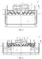
- Figure 4 shows the paving screed 7 in a schematic plan view with extended extension parts 12. By widening the paving screed 7 in this way, a larger working width B can be created for the newly created paving layer 2.
- Figure 4 shows that the cross-distribution channel 15 is extended sideways, beyond the plank base body 11. Along the widened cross-distribution channel 15, the paving material 6 thrown off by the scraper belt 9 can be transported to the outer sides of the extension parts 12. The inside of the cross-distribution channel 15 in Figure 4 arranged cross distributor arrangement 10 is also extended.
- the transverse distribution channel 15 installed in front of the paving screed 7 is supported at its outer areas transversely to the paving direction R by means of Channel plates 16 and pre-scrapers 17 attached to the side of the screed base body 11.
- the channel plates 16 and the pre-scraper 17 can be further extended sideways in order to extend the cross distribution channel 15. The same applies analogously to the cross distribution arrangement 10.
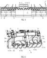
- Figure 5 shows the paving screed 7 with extended extension parts 12 and widening parts 18 attached to the sides to produce a very large working width B for the paving layer 2.
- Figure 5 shows that the transverse distribution channel 15 is formed along the screed base body 11, the extension parts 12 and along the widening parts (attachments) 18 attached thereto, transversely to the installation direction R.
- additional channel plates 16 and pre-scrapers 17 were mounted in order to further expand the transverse distribution channel 15.
- FIG 6 shows a perspective view of an embodiment of the transverse distributor arrangement 10.
- This transverse distributor arrangement 10 is attached to the rear end of the chassis 8 of a road finisher 1.
- the transverse distributor arrangement 10 comprises a distributor auger 19 or a right distributor auger 19a and a left distributor auger 19b (in the installation direction of the road finisher 1). Both distributor augers 19a, 19b are mounted centrally on a screw suspension 20.
- a screw drive (not shown) for driving the two distributor augers 19a, 19b.
- the transverse distribution arrangement 10 comprises a shaft 21. This can be two individual shafts 21 (right shaft 21a, left shaft 21b) or a common shaft 21 of the two distribution screws 19a, 19b.
- the right distribution screw 19a is detachably coupled to the shaft 21a.
- the left distribution screw 19b is detachably coupled to the shaft 21b.
- each shaft 21a, 21b i.e. the end facing away from the auger suspension 20 is mounted in a auger bearing 22a, 22b.
- Each auger bearing 22a, 22b is mounted at the lower end of a auger bearing bracket 23a, 23b.
- These auger bearing brackets 23 have a substantially vertically aligned tube 24a, 24b, which is attached to the chassis 8 of the road paver 1 by means of a fastening plate 25.
- the paving material 6 can comprise a cohesive mixture, such as asphalt, and/or unbound mixture, such as gravel.
- the asphalt mixture can consist of an aggregate mixture with a very high proportion of broken grains and preferably polymer-modified bitumen as a binding agent.
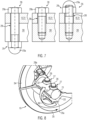
- Such paving materials 6 with hard grains rub against the fastening units 26 of the road finisher 1 that come into contact with the paving material (see Figure 7 , left: screw-nut connection, Figure 7 , middle: screw connection, Figure 7 , right: bolt-nut connection) and cause wear on the fastening units 26, so that the fastening units 26 cannot be easily loosened with a tool such as a wrench.
- the invention provides a wear protection 27 for the fastening units 26, which is Figures 8 - 15 is described in more detail.
- Figure 7 shows an embodiment of a fastening unit 26 used on the road paver 1.
- the fastening unit 26 connects the replaceable component 30 of the road finisher 1 to the chassis 8 or to a working unit 31 of the road finisher 1.
- the working unit 31 can be, for example, the material hopper 4, the longitudinal conveyor device 5, the paving screed 7 or the transverse distributor arrangement 10.
- Replaceable components 30, in particular those against which the paving material 6 flowing from the material hopper 4 to the transverse distributor arrangement 10 rubs, are, for example, the widening parts 18, the channel plates 16, the pre-scrapers 17 and/or the distributor screws 19, 19a, 19b.
- wear protection 27 for the fastening units 26 is described by way of example using the wear protection 27 used on the cross distributor arrangement 10. Such wear protection 27 can also be used for other fastening units 26 of the road finisher 1, in particular for the fastening units 26 of the road finisher 1 that come into contact with the paving material 6.
- FIG 8 shows a perspective view of part of the cross distributor arrangement 10.
- the cross distributor arrangement 10 comprises a shaft 21 (right shaft 21a or left shaft 21b) and a distributor screw 19 detachably coupled to the shaft 21 by means of two fastening units 26.
- the distributor screw 19 has a main body 33 placed on the shaft 21 and a screw blade 34 extending from the main body 33 and running around the shaft 21.
- the distributor screw 19, in particular the main body 33 of the distributor screw 19, is fastened to the shaft 21 of the cross distributor arrangement 10 by means of the fastening units 26.
- the fastening unit 26 is a screw-nut connection.
- the fastening unit 26 comprises a screw 28 with a hexagonal screw head 28a and a screw nut 29 or cap nut 29a attached to the other end of the screw 28 (see the left illustration in the Figure 7 ).
- the wear protection 27 is designed as a sacrificial body 32 for placement on the fastening unit 26.
- the sacrificial body 32 is seated in Figure 8 on the screw nut 29 or on the cap nut 29a of the fastening unit 26 and covers it completely. It is also possible that the sacrificial body 32 does not completely cover the screw nut 29 or the cap nut 29a of the fastening unit 26. On the opposite side, another sacrificial body could be placed on the screw head 28a. Accordingly, the sacrificial body 32 prevents contact and thus friction between the fastening units 26 and the air flowing around the fastening units 26 (or the sacrificial body 32).
- the distributor screw 19 or the screw blade 34 rotates in a direction of rotation 35 during operation of the cross distributor arrangement 10. Relative to this, the installation material 6 moves in a flow direction 36 essentially opposite to the direction of rotation 35 of the distributor screw 19.
- Figure 9 shows a schematic representation of a one-piece embodiment of the sacrificial body 32 ⁇ .
- the sacrificial body 32 ⁇ is designed as a one-piece component 32a (one-piece sacrificial body 32 ⁇ ).
- the one-piece sacrificial body 32 ⁇ has a receiving area 37 with an inner contour 38, which is designed to receive the screw head 28a or the screw nut 29 or the cap nut 29a.
- the receiving area 37 is provided as an opening of the sacrificial body 32 ⁇ .
- the one-piece sacrificial body 32 ⁇ can be arranged/fastened in a form-fitting manner on the hexagonal screw nut 29 or cap nut 29a, or on the hexagonal screw head 28a.
- FIG 10 shows a schematic representation of a multi-part embodiment of the sacrificial body 32".
- the sacrificial body 32" is designed as a multi-part or two-part construction device 32b (two-part sacrificial body 32").
- the two-part sacrificial body 32" has a receiving area 37 ⁇ with an inner contour 38 ⁇ , which is designed to receive the screw head 28a or the screw nut 29 or the cap nut 29a.
- the receiving area 37 ⁇ is provided as an opening of the sacrificial body 32".
- the two-part sacrificial body 32" has two half-shells 40a, 40b. After the half-shells 40a, 40b are each applied to the fastening unit 26, they can be fastened to one another by means of screw connections 41a, 41b.
- Figure 11 shows a perspective view (partial view) of the cross distributor arrangement 10.
- the wear protection 27 is designed in the form of a protective body 42 for the fastening unit 26.
- the protective body 42 is arranged only on a first side 43 of the fastening unit 26 facing the conveyed installation material 6 and shields the fastening unit 26 laterally so that it does not come into contact with the installation material 6 or at least only very little.
- a side (second side) 44 of the fastening unit 26 arranged opposite the side 43 facing the conveyed installation material 6 is free, for example from another protective body 42.
- the fastening unit 26 is freely accessible from the second side 44, for example for a wrench, and can therefore be easily dismantled.
- the main body 33 is designed to accommodate the hexagonal screw head 28a of the fastening unit 26, i.e. on the opposite side of the cap nut 29a (see Figure 13 ), has a recess 39 which positively receives the screw head 28a so that it cannot twist.
- the protective body 42 is designed as an integral component of the distribution screw 19 or the removable screw blade 34 in order to protect the cap nuts 29a of the fastening units 26.
- Figure 11 shows that the distribution screw 19 is assembled from several segments A, B mounted next to each other, ie several screw blades 34.
- Figure 12 shows a perspective view (partial view) of the transverse distributor arrangement 10 with the integral protective body 42 for the fastening unit 26.
- the protective body 42 has a ramp-shaped or curved protective section 45 inclined towards the fastening unit 26.
- the protective body 42 or the protective section 45 extends from the main body 33 of segment A of the distributor screw 19.
- the protective body 42 or the protective section 45 is formed in one piece with the distributor screw 19.
- the protective section 42 extends over an entire height 46 of the screw nut 29 or the cap nut 29a.
- the protective section 45 is formed in the form of a half-shell body 47. The relative flow direction 36 of the installation material 6 and the direction of rotation 35 of the distributor screw 19 are shown.
- Figure 13 shows a schematic representation (partial view) of the transverse distributor arrangement 10 with the protective body 42 for the fastening unit 26.
- the protective section 45 does not extend over an entire height 46 of the screw nut 29 or cap nut 29a.
- the protective section 45 has an inner side 48 and a distance 49 between the inner side 48 of the protective section 45 and the fastening unit 26 varies along a length 50 of the inner side 48.
- the direction of rotation 35 of the distributor screw 19 is indicated.
- the protective body 42, in particular the protective section 45 extends along a direction of curvature K opposite to the direction of rotation 35 of the screw blade 34.
- Figure 14 shows a schematic representation (partial view) of the cross distributor arrangement 10 with another embodiment of the protective body 42.
- the protective body 42 is attached to the shaft 21 as a separate component and has a base part 51 which extends along a circumferential surface 52 of the shaft 21.
- the protective section 45 of the protective body 42 extends in an arc from the base part 51 to an upper end 54 of the cap nut 29a.
- the protective section 45 encloses a predetermined angle with the base part 51.
Landscapes
- Engineering & Computer Science (AREA)
- Architecture (AREA)
- Civil Engineering (AREA)
- Structural Engineering (AREA)
- Road Paving Machines (AREA)
Priority Applications (5)
| Application Number | Priority Date | Filing Date | Title |
|---|---|---|---|
| EP23185195.7A EP4491799A1 (fr) | 2023-07-13 | 2023-07-13 | Finisseuse de route |
| JP2024110467A JP7818655B2 (ja) | 2023-07-13 | 2024-07-09 | 道路舗装機 |
| US18/770,320 US20250019911A1 (en) | 2023-07-13 | 2024-07-11 | Road paver |
| CN202410932047.5A CN119308200A (zh) | 2023-07-13 | 2024-07-12 | 道路摊铺机 |
| CN202421644179.XU CN223017366U (zh) | 2023-07-13 | 2024-07-12 | 道路摊铺机 |
Applications Claiming Priority (1)
| Application Number | Priority Date | Filing Date | Title |
|---|---|---|---|
| EP23185195.7A EP4491799A1 (fr) | 2023-07-13 | 2023-07-13 | Finisseuse de route |
Publications (1)
| Publication Number | Publication Date |
|---|---|
| EP4491799A1 true EP4491799A1 (fr) | 2025-01-15 |
Family
ID=87280669
Family Applications (1)
| Application Number | Title | Priority Date | Filing Date |
|---|---|---|---|
| EP23185195.7A Pending EP4491799A1 (fr) | 2023-07-13 | 2023-07-13 | Finisseuse de route |
Country Status (4)
| Country | Link |
|---|---|
| US (1) | US20250019911A1 (fr) |
| EP (1) | EP4491799A1 (fr) |
| JP (1) | JP7818655B2 (fr) |
| CN (2) | CN119308200A (fr) |
Citations (6)
| Publication number | Priority date | Publication date | Assignee | Title |
|---|---|---|---|---|
| US3485341A (en) * | 1968-03-04 | 1969-12-23 | Kenneth V Lutz | Replaceable shoes for paving augers |
| US7694805B2 (en) * | 2007-12-18 | 2010-04-13 | Caterpillar Paving Products Inc. | Guard assembly and related methods |
| DE202019100903U1 (de) * | 2019-02-18 | 2019-03-12 | Akw Apparate + Verfahren Gmbh | Vorrichtung zur Reinigung verunreinigter Stoffe durch Attrition mittels Rühren in feststoffreichen Suspensionen |
| US10246834B1 (en) * | 2017-11-20 | 2019-04-02 | Caterpillar Paving Products Inc. | Tamper bar and wear plate for screed assembly of paving machine |
| US20210213646A1 (en) * | 2018-05-24 | 2021-07-15 | Compagnie Generale Des Etablissements Michelin | Rotor with anti-wear device and means for attaching same |
| DE102022102095A1 (de) | 2021-02-02 | 2022-08-04 | Caterpillar Paving Products Inc. | Schneckenbohrersegment und dessen systeme, anordnungen und verfahren |
Family Cites Families (4)
| Publication number | Priority date | Publication date | Assignee | Title |
|---|---|---|---|---|
| US4758114A (en) * | 1987-02-17 | 1988-07-19 | M-B-W Inc. | Vibratory concrete screed |
| JPH0676406U (ja) * | 1993-04-16 | 1994-10-28 | 昭和瀝青工業株式会社 | アスファルトプラント用ドライヤー |
| JP2958398B2 (ja) * | 1996-06-18 | 1999-10-06 | ホシザキ電機株式会社 | オーガ式製氷機 |
| EP2169117B1 (fr) * | 2008-09-26 | 2013-07-10 | Joseph Vögele AG | Finisseur |
-
2023
- 2023-07-13 EP EP23185195.7A patent/EP4491799A1/fr active Pending
-
2024
- 2024-07-09 JP JP2024110467A patent/JP7818655B2/ja active Active
- 2024-07-11 US US18/770,320 patent/US20250019911A1/en active Pending
- 2024-07-12 CN CN202410932047.5A patent/CN119308200A/zh active Pending
- 2024-07-12 CN CN202421644179.XU patent/CN223017366U/zh active Active
Patent Citations (6)
| Publication number | Priority date | Publication date | Assignee | Title |
|---|---|---|---|---|
| US3485341A (en) * | 1968-03-04 | 1969-12-23 | Kenneth V Lutz | Replaceable shoes for paving augers |
| US7694805B2 (en) * | 2007-12-18 | 2010-04-13 | Caterpillar Paving Products Inc. | Guard assembly and related methods |
| US10246834B1 (en) * | 2017-11-20 | 2019-04-02 | Caterpillar Paving Products Inc. | Tamper bar and wear plate for screed assembly of paving machine |
| US20210213646A1 (en) * | 2018-05-24 | 2021-07-15 | Compagnie Generale Des Etablissements Michelin | Rotor with anti-wear device and means for attaching same |
| DE202019100903U1 (de) * | 2019-02-18 | 2019-03-12 | Akw Apparate + Verfahren Gmbh | Vorrichtung zur Reinigung verunreinigter Stoffe durch Attrition mittels Rühren in feststoffreichen Suspensionen |
| DE102022102095A1 (de) | 2021-02-02 | 2022-08-04 | Caterpillar Paving Products Inc. | Schneckenbohrersegment und dessen systeme, anordnungen und verfahren |
Also Published As
| Publication number | Publication date |
|---|---|
| US20250019911A1 (en) | 2025-01-16 |
| CN119308200A (zh) | 2025-01-14 |
| CN223017366U (zh) | 2025-06-24 |
| JP2025013260A (ja) | 2025-01-24 |
| JP7818655B2 (ja) | 2026-02-20 |
Similar Documents
| Publication | Publication Date | Title |
|---|---|---|
| DE102014001921B4 (de) | Fräswalze mit einer, insbesondere austauschbaren, Materialleiteinrichtung | |
| EP2613931B1 (fr) | Vis transporteuse | |
| EP3524733B1 (fr) | Éjecteur ou unité d'éjecteur pour une fraiseuse routière ou analogue | |
| DE102014007907B4 (de) | Abstreifeinrichtung mit einer Abstreiferleiste für eine Bodenfräsmaschine und Bodenfräsmaschine mit einer Abstreifeinrichtung | |
| DE10215833A1 (de) | Schneidkörper mit einem Schlegel | |
| EP3057394B1 (fr) | Combinaison d'outils pourvu d'un élément de guidage | |
| WO2016102600A1 (fr) | Système d'outils | |
| DE102010038016C5 (de) | Mischersteg für einen Stabilisierer/Recycler | |
| EP2411582B1 (fr) | Unité d'éjection pour une fraiseuse de route | |
| DE202019002939U1 (de) | Schlegel | |
| DE102010014044B4 (de) | Segment einer Sägekette für hochtourige Motorsägen zum Sägen von Gestein, Beton, Ziegel und Metall | |
| EP3552693A1 (fr) | Distributeur circulaire de tamis et tôle d'usure pour le bras d'étalement d'un distributeur circulaire de tamis | |
| DE102012012615A1 (de) | Auswerfer für eine mobile Bodenbearbeitungsmaschine | |
| DE19703495A1 (de) | Trogmischer, insbesondere Doppelwellen-Trogmischer | |
| DE19856338B4 (de) | Abstreifvorrichtung für Förderbänder | |
| DE102022102095A1 (de) | Schneckenbohrersegment und dessen systeme, anordnungen und verfahren | |
| DE102020001828B4 (de) | Aufnahmevorrichtung an einer Erntemaschine | |
| EP3757290B1 (fr) | Dispositif distributeur transversal pour une finisseuse de route | |
| EP0529113A1 (fr) | Dispositif d'extraction pour silo | |
| DE202025104774U1 (de) | Reißzahnanordnung einer Zerkleinerungsvorrichtung | |
| DE202012104258U1 (de) | Verschleißschutzeinrichtung mit einem Verschleißschutzelement für einen Mischarm eines Trockenmischers | |
| EP1867226A1 (fr) | Barre de coupe pour produit à découper | |
| DE102022211813A1 (de) | VERSCHLEIßPOLSTER FÜR EIN LAUFFLÄCHENGLIED EINER GLEISKETTE EINES KETTENLAUF-WERKS EINER BAUMASCHINE, LAUFFLÄCHENGLIED FÜR EINE GLEISKETTE, GLEISKETTE FÜR EIN KETTENLAUFWERK EINER BAUMASCHINE, BAUMASCHINE SOWIE VERFAHREN ZUM ÜBERTRAGEN VON AUFSTANDSKRÄFTEN EINER BAUMASCHINE IN EINE BASISPLATTE EINES LAUFFLÄCHENGLIEDS | |
| WO2019185236A1 (fr) | Dispositif de mélange de fibres ou de particules et agent liant | |
| EP1127981A2 (fr) | Dispositif avec réservoir intermediaire pour épandre des produits granulaires préhumidifiés |
Legal Events
| Date | Code | Title | Description |
|---|---|---|---|
| PUAI | Public reference made under article 153(3) epc to a published international application that has entered the european phase |
Free format text: ORIGINAL CODE: 0009012 |
|
| STAA | Information on the status of an ep patent application or granted ep patent |
Free format text: STATUS: THE APPLICATION HAS BEEN PUBLISHED |
|
| AK | Designated contracting states |
Kind code of ref document: A1 Designated state(s): AL AT BE BG CH CY CZ DE DK EE ES FI FR GB GR HR HU IE IS IT LI LT LU LV MC ME MK MT NL NO PL PT RO RS SE SI SK SM TR |
|
| STAA | Information on the status of an ep patent application or granted ep patent |
Free format text: STATUS: REQUEST FOR EXAMINATION WAS MADE |
|
| 17P | Request for examination filed |
Effective date: 20250130 |
|
| P01 | Opt-out of the competence of the unified patent court (upc) registered |
Free format text: CASE NUMBER: APP_5356/2025 Effective date: 20250131 |
|
| STAA | Information on the status of an ep patent application or granted ep patent |
Free format text: STATUS: EXAMINATION IS IN PROGRESS |
|
| 17Q | First examination report despatched |
Effective date: 20250627 |