EP4491968A1 - Ensemble destiné à être placé sur le faîte d'un toit - Google Patents
Ensemble destiné à être placé sur le faîte d'un toit Download PDFInfo
- Publication number
- EP4491968A1 EP4491968A1 EP23184471.3A EP23184471A EP4491968A1 EP 4491968 A1 EP4491968 A1 EP 4491968A1 EP 23184471 A EP23184471 A EP 23184471A EP 4491968 A1 EP4491968 A1 EP 4491968A1
- Authority
- EP
- European Patent Office
- Prior art keywords
- panel
- panels
- roof
- ridge
- assembly
- Prior art date
- Legal status (The legal status is an assumption and is not a legal conclusion. Google has not performed a legal analysis and makes no representation as to the accuracy of the status listed.)
- Pending
Links
Images


Classifications
-
- F—MECHANICAL ENGINEERING; LIGHTING; HEATING; WEAPONS; BLASTING
- F24—HEATING; RANGES; VENTILATING
- F24S—SOLAR HEAT COLLECTORS; SOLAR HEAT SYSTEMS
- F24S20/00—Solar heat collectors specially adapted for particular uses or environments
- F24S20/60—Solar heat collectors integrated in fixed constructions, e.g. in buildings
- F24S20/67—Solar heat collectors integrated in fixed constructions, e.g. in buildings in the form of roof constructions
-
- E—FIXED CONSTRUCTIONS
- E04—BUILDING
- E04B—GENERAL BUILDING CONSTRUCTIONS; WALLS, e.g. PARTITIONS; ROOFS; FLOORS; CEILINGS; INSULATION OR OTHER PROTECTION OF BUILDINGS
- E04B7/00—Roofs; Roof construction with regard to insulation
- E04B7/02—Roofs; Roof construction with regard to insulation with plane sloping surfaces, e.g. saddle roofs
- E04B7/06—Constructions of roof intersections or hipped ends
-
- E—FIXED CONSTRUCTIONS
- E04—BUILDING
- E04D—ROOF COVERINGS; SKY-LIGHTS; GUTTERS; ROOF-WORKING TOOLS
- E04D13/00—Special arrangements or devices in connection with roof coverings; Protection against birds; Roof drainage ; Sky-lights
- E04D13/17—Ventilation of roof coverings not otherwise provided for
- E04D13/174—Ventilation of roof coverings not otherwise provided for on the ridge of the roof
-
- E—FIXED CONSTRUCTIONS
- E04—BUILDING
- E04D—ROOF COVERINGS; SKY-LIGHTS; GUTTERS; ROOF-WORKING TOOLS
- E04D3/00—Roof covering by making use of flat or curved slabs or stiff sheets
- E04D3/36—Connecting; Fastening
- E04D3/361—Connecting; Fastening by specially-profiled marginal portions of the slabs or sheets
-
- H—ELECTRICITY
- H02—GENERATION; CONVERSION OR DISTRIBUTION OF ELECTRIC POWER
- H02S—GENERATION OF ELECTRIC POWER BY CONVERSION OF INFRARED RADIATION, VISIBLE LIGHT OR ULTRAVIOLET LIGHT, e.g. USING PHOTOVOLTAIC [PV] MODULES
- H02S20/00—Supporting structures for PV modules
- H02S20/20—Supporting structures directly fixed to an immovable object
- H02S20/22—Supporting structures directly fixed to an immovable object specially adapted for buildings
- H02S20/23—Supporting structures directly fixed to an immovable object specially adapted for buildings specially adapted for roof structures
-
- E—FIXED CONSTRUCTIONS
- E04—BUILDING
- E04D—ROOF COVERINGS; SKY-LIGHTS; GUTTERS; ROOF-WORKING TOOLS
- E04D12/00—Non-structural supports for roofing materials, e.g. battens, boards
- E04D12/004—Battens
- E04D12/006—Batten-supporting means
- E04D12/008—Ridge-batten brackets
-
- F—MECHANICAL ENGINEERING; LIGHTING; HEATING; WEAPONS; BLASTING
- F24—HEATING; RANGES; VENTILATING
- F24S—SOLAR HEAT COLLECTORS; SOLAR HEAT SYSTEMS
- F24S20/00—Solar heat collectors specially adapted for particular uses or environments
- F24S20/60—Solar heat collectors integrated in fixed constructions, e.g. in buildings
- F24S20/69—Solar heat collectors integrated in fixed constructions, e.g. in buildings in the form of shingles or tiles
-
- Y—GENERAL TAGGING OF NEW TECHNOLOGICAL DEVELOPMENTS; GENERAL TAGGING OF CROSS-SECTIONAL TECHNOLOGIES SPANNING OVER SEVERAL SECTIONS OF THE IPC; TECHNICAL SUBJECTS COVERED BY FORMER USPC CROSS-REFERENCE ART COLLECTIONS [XRACs] AND DIGESTS
- Y02—TECHNOLOGIES OR APPLICATIONS FOR MITIGATION OR ADAPTATION AGAINST CLIMATE CHANGE
- Y02B—CLIMATE CHANGE MITIGATION TECHNOLOGIES RELATED TO BUILDINGS, e.g. HOUSING, HOUSE APPLIANCES OR RELATED END-USER APPLICATIONS
- Y02B10/00—Integration of renewable energy sources in buildings
- Y02B10/20—Solar thermal
-
- Y—GENERAL TAGGING OF NEW TECHNOLOGICAL DEVELOPMENTS; GENERAL TAGGING OF CROSS-SECTIONAL TECHNOLOGIES SPANNING OVER SEVERAL SECTIONS OF THE IPC; TECHNICAL SUBJECTS COVERED BY FORMER USPC CROSS-REFERENCE ART COLLECTIONS [XRACs] AND DIGESTS
- Y02—TECHNOLOGIES OR APPLICATIONS FOR MITIGATION OR ADAPTATION AGAINST CLIMATE CHANGE
- Y02E—REDUCTION OF GREENHOUSE GAS [GHG] EMISSIONS, RELATED TO ENERGY GENERATION, TRANSMISSION OR DISTRIBUTION
- Y02E10/00—Energy generation through renewable energy sources
- Y02E10/40—Solar thermal energy, e.g. solar towers
- Y02E10/47—Mountings or tracking
-
- Y—GENERAL TAGGING OF NEW TECHNOLOGICAL DEVELOPMENTS; GENERAL TAGGING OF CROSS-SECTIONAL TECHNOLOGIES SPANNING OVER SEVERAL SECTIONS OF THE IPC; TECHNICAL SUBJECTS COVERED BY FORMER USPC CROSS-REFERENCE ART COLLECTIONS [XRACs] AND DIGESTS
- Y02—TECHNOLOGIES OR APPLICATIONS FOR MITIGATION OR ADAPTATION AGAINST CLIMATE CHANGE
- Y02E—REDUCTION OF GREENHOUSE GAS [GHG] EMISSIONS, RELATED TO ENERGY GENERATION, TRANSMISSION OR DISTRIBUTION
- Y02E10/00—Energy generation through renewable energy sources
- Y02E10/50—Photovoltaic [PV] energy
Definitions
- the present invention relates to an assembly for placement on the ridge of a roof.
- the invention also relates to a building construction comprising a ridged roof, wherein the assembly according to any of the claims is positioned over the ridge of said roof.
- the invention also relates to a method of constructing a building comprising placing the assembly over the ridge of a roof.
- Roofs of buildings such as houses, often contain functional elements such as photovoltaic collectors, thermal collectors or a combination thereof, skylights, ventilation elements and/or ducting terminals, for instance a chimney, a terminal of a heat recovery system or a terminal of a central heating system.
- functional elements such as photovoltaic collectors, thermal collectors or a combination thereof, skylights, ventilation elements and/or ducting terminals, for instance a chimney, a terminal of a heat recovery system or a terminal of a central heating system.
- the present invention aims to overcome these problems.
- the invention in a first aspect relates to an assembly for placement on the ridge of a roof construction, comprising a first panel and a second panel, wherein at least one of the first and second panel comprises one or more integrated functional element; wherein the first and second panels are connected to each other via a hinged connection part which allows an adjustable angle between the first and second panel.
- the invention in a second aspect relates to a building construction comprising a ridged roof, wherein the assembly according to the first aspect is positioned over the ridge of a roof construction of said building with the first panel on one side of the ridge and the second panel on the opposite side of the ridge.
- the invention in a third aspect relates to method of constructing a building, and in particular a roof thereof, comprising placing the assembly of the first aspect over the ridge of a roof construction with the first panel on one side of the ridge and the second panel on the opposite side of the ridge.
- the present invention is based on an assembly that can be placed and installed over the top ridge of a roof of a building with a sloped roof.
- the assembly comprises a first panel and a second panel wherein at least one of the first and second panel comprises one or more integrated functional element(s), wherein the first and second panels are connected to each other via a hinged connection part which allows an adjustable angle between the first and second panel.
- the first and second panels have the hinged part on a first end of the panels. Because the hinged connection part is intended to be positioned on the ridge or top of a roof construction, these first ends are intended to form the upper ends of the panels when placed on a roof construction. In line with this, the second ends of the panels opposite to the hinged connection part form bottom ends of the panels when the assembly is placed on a roof construction.
- the assembly according to the invention Before mounting it onto a roof construction the assembly according to the invention can be prefabricated, assembled and quality controlled in a controlled environment and under optimal circumstances.
- the assembly can be hoisted as a whole and in one part onto the roof construction. Any functional elements can be positioned easily and quickly on a roof construction, by hoisting it on the roof construction, for instance using crane.
- the present invention limits the work required on the roof, which facilitates construction and reduces risks of work accidents.
- the present invention allows to finish a roof in a very limited so that the roof is only open for a limited amount of time. This is in particularly advantageous in case of suboptimal weather conditions, such as rain, snow etc.
- the assembly can be placed and installed on the roof battens of the construction which allows sufficient ventilation under the panels.
- the present invention finds particular suitability in new-build developments, although the assembly of the invention can of course also be used during renovation and sustainability improvement work in the replacement of roofs or roof parts of existing buildings, such as houses.
- the assembly comprises a first panel and a second panel connected to each other via a hinge connection part.
- the hinge of the hinge connection part is not limited to a specific type of hinge. As such it can be defined as any movable joint that allows to adjust the angle between the first and second panels.
- the connecting hinge may be any suitable hinge for these purposes that is sufficiently strong to carry the weight of the panels hanging on it at both sides of a ridge of a roof construction.
- Hinges of the butt type may for instance be suitable in this context. This type of hinge is constructed of two opposite plates connected by a central pin and barrel system.
- the hinge connection part may comprise a single hinge extending over a substantial or full part of the first end of the panels or may comprise multiple hinges distributed over a substantial or full part of the first end of the panels.
- ridge tiles When positioned over the ridge of a roof construction of a building with the first panel on one side of the ridge and the second panel on the opposite side of the ridge, measures may be taken to avoid water ingress into the building via the top (i.e. via the hinge connection of the assembly.
- ridge tiles may be mounted and fixed to the assembly to provide a cover over the hinge connection part.
- Such ridge tiles preferably also overlap the first (top) ends of the first and second panels to a small extent to maximally avoid water ingress via the top of the roof.
- the first panel comprises a first arched flange and the second panel comprises a second arched flange; wherein the first and second arched flanges are configured to protrude at least partially over the hinged connection and overlay each other at least partially when the assembly is placed on the ridge of a roof construction.
- These flanges can be included in the prefabricated assembly so that no substantial additional work on the roof is required in the sense of covering the hinge connection.
- the flanges can slide over each other when upon adjusting the angle between the first and second panel via the hinge connection to create the desired slope and provide a cover over the hinge connection part to avoid water ingress. It is preferred that the flanges overlap for a major part of the arches when the assembly is mounted on the ridge, so as to minimize the risk of water ingress. This way the hinged connection part can form a watertight top of the roof.
- the arched flanges may be fixed to a base material or frame of the first and second panels or may be integral with the base material or frame of the first and second panels.
- the first and second panels may comprise a base material or frame to which functional elements may be mounted to be integrated in the panel.
- the panel may comprise multiple smaller panels arranged in an array of one or more rows next to each other and/or below each other.
- the functional elements are integrated in the panels.
- integrated means that the functional elements may be included on or through the panels or form the panels as such.
- the functional elements may be integrated on a panel surface or through the panel or any other suitable way.
- the assembly may comprise one functional element integrated in one of the first or second panel.
- the assembly comprises multiple different functional elements integrated in at least one of the first and second panel.
- the assembly of the invention is used in the collection of solar energy, because the present invention allows solar panels to be mounted on a roof from above instead of from below, as is custom in present practice.
- High placement of solar panels is preferred because the higher a solar panel is placed the more sunlight will be captured, in particular in view of the increasing absence of shadow-casting objects.
- at least one of the first and second panel comprises one or more solar panels, such as one or more photovoltaic collector, thermal collector or a combination thereof, as functional elements.
- These collectors may be mounted on a base material such as a wooden plate or any other suitable material or on a base from. Alternatively, it is also conceivable that a collector forms the first or second panel.
- these collectors are arranged in arrays of multiple solar panels arranged on the first and/or second panel in an array of one or more rows next to each other and/or below each other. It is preferred that within such an array a so-called dummy panel is provided behind or within which elements for supporting photovoltaic or thermal collectors are arranged. Such supporting elements may include cable work, electrical circuitry and any other means known in the art for supporting collections and processing of solar energy.
- at least one of the first and second panels comprises a panel part that accommodates support elements as functional elements for functional support of said solar panels.
- at least one of the first and second panels comprises a panel part that accommodates support elements support elements for functional support of said one or more solar panel as well as a panel part that accommodates one or more solar panel.
- a function element in the context of the invention may relate to a different application.
- functional parts may be skylights, ventilation elements and/or ducting terminals, for instance a chimney, a terminal of a heat recovery system or a terminal of a central heating system.
- at least one of the first and second panels comprises one or more parts accommodating skylight as functional element.
- at least one of the first and second panels may comprise one or more parts accommodating a ventilation element and/or a roof terminal of a duct as functional element.
- one or more ventilation elements are provided as part of the hinged connection part.
- Such ventilation elements may for instance be provided at opposite terminal parts of the hinged connection part (as seen in the longitudinal direction of the roof ridge) and may be passive ventilation elements or powered ventilation elements (active ventilation elements). It is preferred to include passive ventilation elements at opposite ends of the hinged connection part (as seen in the longitudinal direction of the roof ridge). The inclusion of ventilation elements in the hinged connection allows to ventilate the roof construction via the ridge, so that adequate ventilation is achieved.
- first and second panels can be expanded at the side ends.
- first and second panels can be expanded the bottom (second) ends, for instance with another row of solar panels or any other elements.
- This allows further flexibility with regard to the use of the assembly because it can be customed to any roof. For instance, in case the opposite sides of a roof differ in size. Therefore, it is preferred that the assembly comprising mounting elements on the ends of the panels opposite to the arched flanges or on the sides of the panel for mounting further roof elements to the first and/or second panels.
- Such mounting elements may for instance be in the form of (rectangular) hook connectors, wherein a hook connector of the first and/or second panel can engage with a respective hook connector of a structure to be mounted thereto, such as another row of solar panels.
- the first and second panels may be provided with any other functional elements, for instance for optimizing prevention of water ingress, for instance using further flanges or gutters, etc.
- the roof can be finished off in line with customary practice in the art. This may for instance involve sealing the lower edges and/or side edges of the panels to the roof construction or an existing roof part. Suitable approaches for this include using a lead or lead-substitute slab. Such a lead or lead-substitute slab may also be prefabricated with the assembly and form part of the assembly as such.
- Figures 1 - 3 show an exemplary embodiment of an assembly according to the invention.
- Figure 1A shows the assembly prior to mounting it on a roof construction.
- Figure 1B shows the assembly when placed on a roof construction 40 of a building 30.
- the assembly comprises a comprising a first panel 1 and a second panel 2, wherein both first and second panel comprise an array of solar panels 3.
- the second panel 2 comprises, apart from an array of solar panels 3 also a so-called dummy panel 6. Any supporting equipment for the solar panels can be installed behind or in this dummy panel. Also further functional elements, such as duct terminal 7 can be installed in the dummy panel 6 to make optimal use of the panel surface.
- Fig. 2 which shows the part indicated with II in Fig. 1A in detail
- the first and second panels 1, 2 are connected to each other via a hinged connection part 4 which allows an adjustable angle between the first and second panel 1, 2.
- first panel 1 comprises a first arched flange 11 and the second panel comprises a second arched flange 12.
- the first and second arched flanges 11, 12 extend for a major part thereof over the hinged connection 4 and overlay each other at least partially when the assembly is placed on the ridge 5 of a roof construction as in Fig. 1B .
- the roof can be finished off in line with customary practice in the art. In the present embodiment this involve sealing at least the lower edges of the panels to the roof construction 40.
- a lead or lead-substitute slab 8 is used for this as can be seen in Fig.1 .
- Such a lead or lead-substitute slab 8 may also be prefabricated with the assembly and form part of the assembly as such.
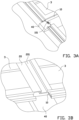
- the first and second panels can be expanded at the side ends and/or at the bottom ends, for instance with another row of solar panels, such as the lower row in the first panel. Therefore, as shown in Fig.3A and B the assembly of this embodiment comprises mounting elements in the form of rectangular hook connectors 10, 101, 20, 201.
- Fig. 3A shows that a hook connector 10 of the second panel 2 in the horizontal plane thereof can engage with a respective hook connector 101 of a structure to be mounted thereto, such as the lower row of solar panels of the second panel 2.
- the sides of the panels can be expanded when desired, as shown in Fig. 3B wherein a hook connector 20 of the second panel extending in the direction between the top and bottom ends thereof can engage with a respective hook connector 201 of a structure to be mounted thereto.
Landscapes
- Engineering & Computer Science (AREA)
- Architecture (AREA)
- Civil Engineering (AREA)
- Structural Engineering (AREA)
- Mechanical Engineering (AREA)
- Physics & Mathematics (AREA)
- Electromagnetism (AREA)
- Life Sciences & Earth Sciences (AREA)
- Sustainable Development (AREA)
- Sustainable Energy (AREA)
- Thermal Sciences (AREA)
- Chemical & Material Sciences (AREA)
- Combustion & Propulsion (AREA)
- General Engineering & Computer Science (AREA)
- Roof Covering Using Slabs Or Stiff Sheets (AREA)
Priority Applications (1)
| Application Number | Priority Date | Filing Date | Title |
|---|---|---|---|
| EP23184471.3A EP4491968A1 (fr) | 2023-07-10 | 2023-07-10 | Ensemble destiné à être placé sur le faîte d'un toit |
Applications Claiming Priority (1)
| Application Number | Priority Date | Filing Date | Title |
|---|---|---|---|
| EP23184471.3A EP4491968A1 (fr) | 2023-07-10 | 2023-07-10 | Ensemble destiné à être placé sur le faîte d'un toit |
Publications (1)
| Publication Number | Publication Date |
|---|---|
| EP4491968A1 true EP4491968A1 (fr) | 2025-01-15 |
Family
ID=87202295
Family Applications (1)
| Application Number | Title | Priority Date | Filing Date |
|---|---|---|---|
| EP23184471.3A Pending EP4491968A1 (fr) | 2023-07-10 | 2023-07-10 | Ensemble destiné à être placé sur le faîte d'un toit |
Country Status (1)
| Country | Link |
|---|---|
| EP (1) | EP4491968A1 (fr) |
Citations (8)
| Publication number | Priority date | Publication date | Assignee | Title |
|---|---|---|---|---|
| US4962692A (en) * | 1989-07-31 | 1990-10-16 | Shuert Lyle H | Roof ridge vent |
| US5022203A (en) * | 1990-07-27 | 1991-06-11 | The Louis Berkman Company | Vent ridge assembly |
| GB2266545A (en) * | 1992-04-30 | 1993-11-03 | Ultraframe Plc | Ventilated glazed roof |
| DE4444439A1 (de) * | 1994-12-14 | 1995-04-27 | Karl Gebhardt | Solarenergieanlage sowie Montageelement dafür |
| NL1017435C2 (nl) * | 2001-02-22 | 2002-01-24 | Hakvoort Marcus Bernhardus J | Lichtdoorlatende zadel-, shed- en/of noorderlichtdak constructie. |
| ITTV20100064A1 (it) * | 2010-04-15 | 2011-10-16 | Deplimax S R L | Struttura di copertura del colmo di tetti autoventilati |
| US20120012157A1 (en) * | 2009-01-12 | 2012-01-19 | Universidad Politecnica De Madrid | System of mobile solar panels for construction |
| EP3922781A1 (fr) * | 2020-06-12 | 2021-12-15 | VKR Holding A/S | Système de panneaux ayant un profil d'installation comportant une ou plusieurs sections de bordure et procédé d'adaptation d'un tel système de panneaux |
-
2023
- 2023-07-10 EP EP23184471.3A patent/EP4491968A1/fr active Pending
Patent Citations (8)
| Publication number | Priority date | Publication date | Assignee | Title |
|---|---|---|---|---|
| US4962692A (en) * | 1989-07-31 | 1990-10-16 | Shuert Lyle H | Roof ridge vent |
| US5022203A (en) * | 1990-07-27 | 1991-06-11 | The Louis Berkman Company | Vent ridge assembly |
| GB2266545A (en) * | 1992-04-30 | 1993-11-03 | Ultraframe Plc | Ventilated glazed roof |
| DE4444439A1 (de) * | 1994-12-14 | 1995-04-27 | Karl Gebhardt | Solarenergieanlage sowie Montageelement dafür |
| NL1017435C2 (nl) * | 2001-02-22 | 2002-01-24 | Hakvoort Marcus Bernhardus J | Lichtdoorlatende zadel-, shed- en/of noorderlichtdak constructie. |
| US20120012157A1 (en) * | 2009-01-12 | 2012-01-19 | Universidad Politecnica De Madrid | System of mobile solar panels for construction |
| ITTV20100064A1 (it) * | 2010-04-15 | 2011-10-16 | Deplimax S R L | Struttura di copertura del colmo di tetti autoventilati |
| EP3922781A1 (fr) * | 2020-06-12 | 2021-12-15 | VKR Holding A/S | Système de panneaux ayant un profil d'installation comportant une ou plusieurs sections de bordure et procédé d'adaptation d'un tel système de panneaux |
Similar Documents
| Publication | Publication Date | Title |
|---|---|---|
| US12047030B2 (en) | Waterproofing mounting system for attaching solar modules to a roof | |
| US20250330112A1 (en) | Waterproofing Mounting System for Attaching Solar Modules to a Roof | |
| CN103875178B (zh) | 太阳电池组件的固定构造 | |
| EP2917430B1 (fr) | Structure de bâtiment comportant un toit sur lequel un équipement peut être monté | |
| EP2105971A1 (fr) | Toiture inclinée avec un support pour panneaux solaires | |
| EP4491968A1 (fr) | Ensemble destiné à être placé sur le faîte d'un toit | |
| JP3555719B2 (ja) | 太陽電池の取付け装置 | |
| CZ309498A3 (cs) | Fotoelektrický systém pro šikmou střechu | |
| JPH11336210A (ja) | 太陽光発電パネル設置型屋根の換気構造 | |
| US20240266987A1 (en) | Waterproofing Mounting System for Attaching Solar Modules to a Roof | |
| US20260002363A1 (en) | Modular roof structure | |
| EP4085173B1 (fr) | Système d'élément de toiture | |
| EP2696151A2 (fr) | Structure de support modulaire pour un système d'énergie solaire | |
| JP2002194866A (ja) | 太陽エネルギー収集装置 | |
| JP2003184245A (ja) | 太陽電池瓦雪止め構造および太陽電池瓦用雪止め具 | |
| US12620926B2 (en) | Waterproofing mounting system for attaching solar modules to a roof | |
| US20220416715A1 (en) | System for mounting tiles over a surface | |
| CN121381855A (zh) | 房屋构造 | |
| AU2019204459B2 (en) | A Roof | |
| JP3262502B2 (ja) | 太陽電池屋根構造 | |
| JP2629140B2 (ja) | 太陽エネルギー活用装置の屋根への設置構造 | |
| CN121497056A (zh) | 用于斜屋面的天窗与光伏安装施工方法 | |
| JP2007138526A (ja) | 外装構造 |
Legal Events
| Date | Code | Title | Description |
|---|---|---|---|
| PUAI | Public reference made under article 153(3) epc to a published international application that has entered the european phase |
Free format text: ORIGINAL CODE: 0009012 |
|
| STAA | Information on the status of an ep patent application or granted ep patent |
Free format text: STATUS: THE APPLICATION HAS BEEN PUBLISHED |
|
| AK | Designated contracting states |
Kind code of ref document: A1 Designated state(s): AL AT BE BG CH CY CZ DE DK EE ES FI FR GB GR HR HU IE IS IT LI LT LU LV MC ME MK MT NL NO PL PT RO RS SE SI SK SM TR |
|
| STAA | Information on the status of an ep patent application or granted ep patent |
Free format text: STATUS: REQUEST FOR EXAMINATION WAS MADE |
|
| 17P | Request for examination filed |
Effective date: 20250429 |
|
| STAA | Information on the status of an ep patent application or granted ep patent |
Free format text: STATUS: EXAMINATION IS IN PROGRESS |
|
| 17Q | First examination report despatched |
Effective date: 20251217 |