EP4492422A1 - Verfahren zur erkennung einer verschlechterung einer schaltvorrichtung mit einem elektromagnetischen aktuator - Google Patents
Verfahren zur erkennung einer verschlechterung einer schaltvorrichtung mit einem elektromagnetischen aktuator Download PDFInfo
- Publication number
- EP4492422A1 EP4492422A1 EP24186903.1A EP24186903A EP4492422A1 EP 4492422 A1 EP4492422 A1 EP 4492422A1 EP 24186903 A EP24186903 A EP 24186903A EP 4492422 A1 EP4492422 A1 EP 4492422A1
- Authority
- EP
- European Patent Office
- Prior art keywords
- electromagnetic actuator
- determined
- polynomial
- reaction time
- values
- Prior art date
- Legal status (The legal status is an assumption and is not a legal conclusion. Google has not performed a legal analysis and makes no representation as to the accuracy of the status listed.)
- Granted
Links
Images

Classifications
-
- H—ELECTRICITY
- H01—ELECTRIC ELEMENTS
- H01H—ELECTRIC SWITCHES; RELAYS; SELECTORS; EMERGENCY PROTECTIVE DEVICES
- H01H47/00—Circuit arrangements not adapted to a particular application of the relay and designed to obtain desired operating characteristics or to provide energising current
- H01H47/002—Monitoring or fail-safe circuits
-
- G—PHYSICS
- G01—MEASURING; TESTING
- G01R—MEASURING ELECTRIC VARIABLES; MEASURING MAGNETIC VARIABLES
- G01R31/00—Arrangements for testing electric properties; Arrangements for locating electric faults; Arrangements for electrical testing characterised by what is being tested not provided for elsewhere
- G01R31/327—Testing of circuit interrupters, switches or circuit-breakers
- G01R31/3271—Testing of circuit interrupters, switches or circuit-breakers of high voltage or medium voltage devices
- G01R31/3272—Apparatus, systems or circuits therefor
- G01R31/3274—Details related to measuring, e.g. sensing, displaying or computing; Measuring of variables related to the contact pieces, e.g. wear, position or resistance
-
- G—PHYSICS
- G01—MEASURING; TESTING
- G01R—MEASURING ELECTRIC VARIABLES; MEASURING MAGNETIC VARIABLES
- G01R31/00—Arrangements for testing electric properties; Arrangements for locating electric faults; Arrangements for electrical testing characterised by what is being tested not provided for elsewhere
- G01R31/327—Testing of circuit interrupters, switches or circuit-breakers
- G01R31/3271—Testing of circuit interrupters, switches or circuit-breakers of high voltage or medium voltage devices
- G01R31/3275—Fault detection or status indication
-
- G—PHYSICS
- G01—MEASURING; TESTING
- G01R—MEASURING ELECTRIC VARIABLES; MEASURING MAGNETIC VARIABLES
- G01R31/00—Arrangements for testing electric properties; Arrangements for locating electric faults; Arrangements for electrical testing characterised by what is being tested not provided for elsewhere
- G01R31/327—Testing of circuit interrupters, switches or circuit-breakers
- G01R31/3277—Testing of circuit interrupters, switches or circuit-breakers of low voltage devices, e.g. domestic or industrial devices, such as motor protections, relays, rotation switches
-
- H—ELECTRICITY
- H01—ELECTRIC ELEMENTS
- H01H—ELECTRIC SWITCHES; RELAYS; SELECTORS; EMERGENCY PROTECTIVE DEVICES
- H01H71/00—Details of the protective switches or relays covered by groups H01H73/00 - H01H83/00
- H01H71/04—Means for indicating condition of the switching device
- H01H2071/044—Monitoring, detection or measuring systems to establish the end of life of the switching device, can also contain other on-line monitoring systems, e.g. for detecting mechanical failures
-
- H—ELECTRICITY
- H01—ELECTRIC ELEMENTS
- H01H—ELECTRIC SWITCHES; RELAYS; SELECTORS; EMERGENCY PROTECTIVE DEVICES
- H01H3/00—Mechanisms for operating contacts
- H01H3/22—Power arrangements internal to the switch for operating the driving mechanism
- H01H3/30—Power arrangements internal to the switch for operating the driving mechanism using spring motor
- H01H3/3031—Means for locking the spring in a charged state
-
- H—ELECTRICITY
- H01—ELECTRIC ELEMENTS
- H01H—ELECTRIC SWITCHES; RELAYS; SELECTORS; EMERGENCY PROTECTIVE DEVICES
- H01H3/00—Mechanisms for operating contacts
- H01H3/22—Power arrangements internal to the switch for operating the driving mechanism
- H01H3/30—Power arrangements internal to the switch for operating the driving mechanism using spring motor
- H01H3/3052—Linear spring motors
-
- H—ELECTRICITY
- H01—ELECTRIC ELEMENTS
- H01H—ELECTRIC SWITCHES; RELAYS; SELECTORS; EMERGENCY PROTECTIVE DEVICES
- H01H71/00—Details of the protective switches or relays covered by groups H01H73/00 - H01H83/00
- H01H71/10—Operating or release mechanisms
- H01H71/12—Automatic release mechanisms with or without manual release
- H01H71/24—Electromagnetic mechanisms
- H01H71/2463—Electromagnetic mechanisms with plunger type armatures
Definitions
- the present invention relates to the field of switching devices for electrical equipment, for example for low and medium voltage electrical equipment.
- the switching device may for example be a circuit breaker.
- a low or medium voltage switching device may comprise one or more electromagnetic actuators for unlocking a spring control mechanism, for moving a movable electrical contact, so as to open or close an electrical circuit.
- the opening of the electrical circuit is carried out in the event of a fault appearing in the electrical circuit.
- the fault may in particular be a short circuit between two phases, or between a phase and earth. Closing the circuit allows a load to be energized.
- the electromagnetic actuator comprises a movable magnetic core and a control coil. Under the action of an electric current flowing through the control coil, the magnetic core moves.
- the magnetic core is mechanically coupled to the control mechanism acting on the movable electrical contacts so as to be able to open or close the electrical circuit.
- circuit breakers can include measuring circuits to diagnose the state of the electromagnetic actuator in real time.
- This electromagnetic actuator is generally subject to the effects of aging which can gradually degrade its electrical or mechanical functions, and ultimately make it inoperable. It is therefore important for users to be able to monitor changes in the state of the electromagnetic actuator. It is desirable to allow users to intervene to repair or change the electromagnetic actuator at an appropriate time in the management of the electrical network.
- the method for detecting degradation of the switching device is a method for detecting a change in the behavior of the switching device due to the aging of its components. Aging of components includes for example wear, deformations, the effect of corrosion, the evolution of magnetic performances, the evolution of tribological properties of the components.
- the electromagnetic actuator operates nominally, the values of the assembly do not change significantly during successive actuations. In other words, the different values of the assembly are substantially constant.
- a progressive degradation of the electromagnetic actuator tends to cause a change in the values during successive actuations, in particular a fluctuation of these values.
- the values of the assembly are no longer substantially constant and exhibit a significant fluctuation. This progressive evolution makes it possible to detect a degradation of the magnetic actuator of the switching device.
- the method for detecting a degradation of the switching device is a method also making it possible to anticipate the appearance of a fault in the switching device. In fact, uncorrected degradation of the switching device can ultimately lead to the appearance of a fault.
- step (vii) the evolution of the values of the set may be a fluctuation of the values of the set during successive commands of the electromagnetic actuator.
- the set of values of the polynomial of the determined reaction time and the determined quantity is obtained by a succession of consecutive commands of the electromagnetic actuator of the switching device.
- Each value of the set of values of the polynomial of the determined reaction time and the determined quantity corresponds to a separate actuation of the electromagnetic actuator of the switching device.
- the switching device may be a circuit breaker.
- the switching device may be a switch.
- the switching device may be a disconnector.
- the elastic member is configured to apply a driving force to the movable electrical contact.
- the elastic member is connected to a drive element configured to move the movable electrical contact so as to open or close an electrical circuit.
- the drive element comprises, for example, a connecting rod.
- the unlocking member can move from a locking position in which the elastic member of the control mechanism is elastically constrained and in which the movable electrical contact is in the closing position of the electrical circuit, to an unlocked position in which the elastic member of the control mechanism is released and moves the movable electrical contact from the electrical circuit closing position to an electrical circuit opening position.
- the unlocking member can move from a locking position in which the elastic member of the control mechanism is elastically constrained and in which the movable electrical contact is in the opening position of the electrical circuit, to an unlocked position in which the elastic member of the control mechanism is released and moves the movable electrical contact from an opening position of the electrical circuit to the closing position of the electrical circuit.
- Unlocking the control mechanism means releasing the elastic member of the control mechanism. In other words, unlocking the control mechanism is equivalent to moving the unlocking member from the locking position to the releasing position.
- the electromagnetic actuator is an electromagnet.
- the electromagnetic actuator includes a control coil and a magnetic core configured to move under the action of a magnetic field created by a flow of electric current in the control coil.
- the magnetic core is, for example, mobile in translation.
- the magnetic core is mechanically coupled to an unlocking member configured to move from a locking position in which the resilient member is held in a tensioned state to a release position in which the resilient member is free to relax so as to move the electrical contact from the closed position to the open position.
- Measuring a current flowing through the electromagnetic actuator means measuring the intensity of the electric current flowing through the electromagnetic actuator.
- the current flowing in the electromagnetic actuator is detected by an electronic measuring circuit.
- the current flowing through the electromagnetic actuator is sampled, for example with a sampling frequency between 1 kHz and 100 kHz.
- the electromagnetic actuator comprises a coupling element mechanically coupling the magnetic core to the unlocking member.
- the control mechanism may include rotating movable elements.
- the control mechanism may include elements that move in translation.
- the elastic member may be a spring, for example a spiral spring or a helical spring.
- the electromagnetic actuator is configured to trigger a movement of the movable electrical contact in order to open the electrical circuit.
- the electromagnetic actuator is configured to trigger an opening of the electrical circuit in the event of a fault on the electrical circuit.
- the reaction time of the electromagnetic actuator is determined from the temporal variations of the measured current.
- the proposed method therefore does not require the installation of any additional sensor, such as an electrical contact displacement sensor or a sensor for the displacement of an element of the control mechanism.
- the proposed method includes a sub-step of determining the temporal variations of the measured current.
- the reaction time of the electromagnetic actuator is equal to a duration elapsed between an instant of start of circulation of the electric current in the electromagnetic actuator and an instant corresponding to a local minimum value of the electric current circulating in the electromagnetic actuator.
- the quantity representative of the current flowing in the electromagnetic actuator when the switching device is actuated is a local maximum value of the electric current flowing in the electromagnetic actuator.
- the parameter is determined by a polynomial with two indeterminates, i.e. a sum of monomials with two indeterminates.
- a first indeterminate is the determined reaction time
- the second indeterminate is the determined quantity representative of the current flowing in the electromagnetic actuator when the electromagnetic actuator is controlled.
- Each monomial of the polynomial is thus determined by the product: of the determined reaction time, raised to a first given power, of the determined quantity representative of the current flowing in the electromagnetic actuator when the electromagnetic actuator is controlled, raised to a second given power, and of a constant coefficient.
- Each monomial can be written in the form: A i ⁇ ta k i ⁇ i 1 L i
- the polynomial formed from the reaction time of the electromagnetic actuator and the local maximum value of the circuit current in the electromagnetic actuator best accounts for a progressive degradation of this electromagnetic actuator.
- the polynomial is thus a polynomial with two indeterminates.
- the parameter P is equal to the product of the determined reaction time and the determined quantity representative of the current flowing in the electromagnetic actuator when controlling the electromagnetic actuator.
- the polynomial includes a single term, in other words is a monomial.
- the first power of the monomial is equal to 1 and the second power of the monomial is also equal to 1.
- the monomial formed is then equal to the product of the determined reaction time and the determined quantity representative of the current flowing in the electromagnetic actuator when the electromagnetic actuator is controlled, that is to say the result of multiplying the value of the determined reaction time by the value of the determined quantity representative of the current flowing in the electromagnetic actuator when the electromagnetic actuator is controlled.
- the local maximum value of the current is obtained for an instant between an instant of start of circulation of the electric current in the electromagnetic actuator and an instant corresponding to a local minimum of the electric current circulating in the electromagnetic actuator.
- the average value may be a running average calculated from the values corresponding to the actuations preceding the current actuation, and comprising a number of values equal to the predetermined number of actuations.
- the statistical parameter representative of a fluctuation of the values of the set of values of the polynomial of the determined reaction time and of the determined quantity comprises a standard deviation of the values of the polynomial of the determined reaction time and of the determined quantity determined for a set of actuations of the switching device carried out under reference conditions corresponding to a new state of the switching device.
- the set of actuations of the switching device carried out under reference conditions comprises, for example, 20 successive actuations of the switching device.
- the proposed method thus comprises a calibration phase for quantifying the nominal variations of the value of the polynomial of the determined reaction time and of the quantity representative of the current flowing in the electromagnetic actuator when the switching device is actuated. These nominal variations correspond to the variations observed in a reference state in which the switching device has neither manufacturing defect nor wear.
- the reference condition corresponds, for example, to a new condition of the switching device.
- the proposed method comprises a measurement phase in which the variations of the value of the polynomial of the determined reaction time and of the quantity representative of the current flowing in the electromagnetic actuator are analyzed.
- the measurement phase follows the calibration phase.
- the measuring phase is carried out throughout the entire period of use of the switching device.
- the proposed statistical parameter allows a robust detection of a possible degradation of the electromagnetic actuator, while being simple to implement.
- the necessary calculations are easily achievable in real time, which allows a rapid detection of a possible degradation.
- P i the determined value of the polynomial for an actuation of rank i
- D i the calculated value of the statistical parameter for the actuation of rank i
- M a number of actuations taken into account to determine an average value
- K a number of actuations carried out under reference conditions corresponding to a new state of the switching device.
- a degradation of the electromagnetic actuator is determined when the absolute value of the statistical parameter representative of a fluctuation of the polynomial of the determined reaction time and of the determined quantity is greater than a first positive predetermined threshold.
- the value chosen for the first positive predetermined threshold makes it possible to adjust the sensitivity of the proposed detection method.
- the first predetermined positive threshold is for example between 2 and 3.
- an absence of degradation of the electromagnetic actuator is determined when the absolute value of the statistical parameter representative of a fluctuation of the polynomial of the determined reaction time and of the determined quantity is less than or equal to the first positive predetermined threshold.
- a degradation is determined when the absolute value of the statistical parameter takes a value greater than a predefined threshold value. Conversely, an absence of degradation is determined when the absolute value of the statistical parameter takes a value lower than the predefined threshold value.
- the degradation of the electromagnetic actuator is classified into a first type of degradation, called minor degradation, when the absolute value of the statistical parameter representative of a fluctuation of the polynomial of the determined reaction time and of the determined quantity is greater than a first predetermined positive threshold and less than a second predetermined positive threshold.
- the second predetermined positive threshold is for example between 4 and 5.
- the degradation of the electromagnetic actuator is classified into a second type of degradation, called major degradation, when the absolute value of the statistical parameter representative of a fluctuation of the polynomial of the determined reaction time and of the determined quantity is greater than the second positive predetermined threshold.
- the statistical parameter used thus allows a quantification of the severity of the degradation, and not only the presence or absence of degradation.
- the detection method may comprise a step of emitting an alert signal in response to a determination of degradation of the electromagnetic actuator.
- the alert signal emitted allows users to plan and carry out a maintenance or replacement operation on the switching device when it is in a degraded or even defective state.
- No alert signal is issued when no degradation has been determined. In other words, no alert is issued when the proposed method indicates that the electromagnetic actuator is free of degradation.
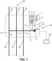
- the electrical circuit 50 comprises three electrical conductors 20, 21, 22, each conductor corresponding to a phase of a medium voltage three-phase network.
- the electrical circuit 50 comprises a switching device 30.
- the switching device 30 may be a circuit breaker. According to one variant, the switching device 30 may be a switch. According to another example of application, the switching device 30 can be a disconnector.
- the electromagnetic actuator 1 is an electromagnet.
- the electromagnetic actuator 1 comprises a control coil 2 and a magnetic core 3 configured to move under the action of a magnetic field created by a flow of electric current in the control coil 2.
- the magnetic core 3 is for example mobile in translation.
- the magnetic core 3 is mechanically coupled to an unlocking member 8 configured to move from a locking position V in which the elastic member 7 is held in a tensioned state to a release position L in which the elastic member 7 is free to relax so as to move the electrical contact 10 from the closed position F to the open position O.
- the movable electrical contact 10 is associated with the electrical conductor 20.
- a movable electrical contact 11 is associated with the electrical conductor 21
- a movable electrical contact 12 is associated with the electrical conductor 22.
- the movable electrical contact 10 is shown in the open position, that is to say in the position where the flow of electric current in the circuit Electric 50 is interrupted.
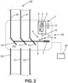
- the movable electrical contact 10 is shown in the closed position, that is to say in the position where the flow of electric current in the electrical circuit 50 is possible.
- the electromagnetic actuator 1 comprises a coupling element 13 mechanically coupling the magnetic core 3 to the unlocking member 8.
- the control mechanism 4 may comprise elements that are movable in rotation.
- the control mechanism 4 may comprise elements that are movable in translation.
- the control mechanism 4 can jointly move the three movable electrical contacts 10, 11, 12.
- the electromagnetic actuator 1 is configured to trigger a movement of the movable electrical contact 10 in order to open the electrical circuit 50.
- the electromagnetic actuator 1 is configured to trigger an opening of the electrical circuit 50 in the event of a fault on the electrical circuit 50.
- a fault that may be present on the electrical circuit 50 is a short circuit between two separate phases. Another type of fault may be a short circuit between a phase and ground.
- the elastic member 7 is configured to apply a driving force to the movable electrical contact 10.
- the elastic member 7 may be a spring, for example a spiral spring or a helical spring.
- the elastic member 7 is connected to a drive element 9 configured to move the movable electrical contact 10 so as to open or close an electrical circuit 50.
- the drive element 9 comprises for example a connecting rod.
- the unlocking member 8 can move from a locking position in which the elastic member 7 of the control mechanism 4 is elastically constrained and in which the movable electrical contact 10 is in the closed position F of the electrical circuit 50, to an unlocked position V in which the elastic member 7 of the control mechanism 4 is released and moves the movable electrical contact 10 from the closed position F of the electrical circuit 50 to an open position O of the electrical circuit 50.
- the unlocking member 8 can pass from a locking position in which the elastic member 7 of the control mechanism 4 is elastically constrained and in which the movable electrical contact 10 is in the open position O of the electrical circuit 50, to an unlocked position V in which the elastic member 7 of the control mechanism 4 is released and moves the movable electrical contact 10 from an opening position O of the electrical circuit 50 to the closing position F of the electrical circuit 50.
- Unlocking the control mechanism 4 means releasing the elastic member 7 from the control mechanism 4.
- the electromagnet 1 makes it possible to control the movement of the unlocking member 8 so as to release the elastic member 7.
- the propulsive force for moving the movable electrical contact 10 is provided by the elastic member 7.
- the electromagnetic actuator 1 has no direct interaction with the movable electrical contact 10.
- the electromagnetic actuator 1 provides a force of electromagnetic origin for moving the unlocking member 8, via the coupling element 13.
- the potential energy stored by the elastic member 7 is released and ensures the movement of the electrical contact 10 via the coupling element training 9.
- the unlocking member 8 is in the locking position V and the elastic member 7, schematized as a helical spring, is maintained in the compressed state.
- the movable contact 10 is in the closed position, corresponding to a circulation of the electric current in the electric conductor 20.
- the coupling element 13 has moved the unlocking member 8 to the release position.
- the elastic member 7 is in the relaxed state, and the drive element 9 has moved the movable electrical contact 10 to its open position, corresponding to an interruption of the flow of current in the electrical conductor 20 and therefore in the electrical circuit 50.
- the mechanical components of the switching device 30 may deteriorate over the lifetime of use of the switching device, in particular due to wear resulting from repeated triggering, deformations and chemical corrosion which may occur. It is therefore desirable to be able to have a method for diagnosing the switching device 30, that is to say a method for detecting the appearance of degradation of the switching device 30.
- the values of the set E do not change substantially during successive actuations. In other words, the different values of the set E are substantially constant. Conversely, a progressive degradation of the electromagnetic actuator 1 tends to cause a change in the values of the set E during successive actuations. The values of the set E are no longer substantially constant and exhibit a significant change. This progressive change makes it possible to detect a degradation of the switching device 30, as well as the presence of a fault.
- the set E of values of the polynomial P of the determined reaction time ta and of the determined quantity i1 is obtained by a succession of consecutive commands of the electromagnetic actuator 1 of the switching device 30.
- Each value of the set E of values of the polynomial P of the determined reaction time ta and of the determined quantity i1 corresponds to a distinct actuation of the electromagnetic actuator 1 of the switching device30.
- a value of the reaction time ta is associated with each of the different actuations of the switching device 30.
- a value of the determined parameter i1 is associated with each of the different actuations of the switching device 30.
- a value of the polynomial P of ta and i1 is associated with each of the actuations of the switching device 30.
- Measuring a current C flowing in the electromagnetic actuator 1 means measuring the intensity of the electric current flowing in the electromagnetic actuator 1. More precisely, the intensity of the electric current flowing in the control coil 2 is measured.
- the current C flowing in the electromagnetic actuator 1 is detected by an electronic measuring circuit.
- the current C flowing in the electromagnetic actuator 1 is sampled, for example with a sampling frequency between 1 kHz and 100 kHz. In other words, the current value is measured periodically during an actuation phase of the electromagnetic actuator 1.
- the reaction time ta of the electromagnetic actuator 1 is determined from the temporal variations of the measured current C.
- the proposed method thus includes a sub-step of determining the temporal variations of the measured current C.
- No sensor other than the current measuring sensor is required to determine the reaction time ta of the electromagnetic actuator 1.
- the reaction time ta of the electromagnetic actuator 1 is equal to a duration elapsed between an instant t0 of start of circulation of the electric current in the electromagnetic actuator 1 and an instant tmin corresponding to a local minimum value of the electric current circulating in the electromagnetic actuator 1.
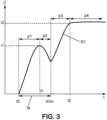
- FIG. 3 schematically represents a curve of the time evolution of the electric current flowing in the electromagnetic actuator 1 when it is controlled. This curve of the intensity as a function of time is designated by the sign G1.
- the curve G1 of the time evolution of the electric current in the electromagnetic actuator 1 comprises a first portion p1 continuously increasing, a second portion p2 continuously decreasing, the second portion p2 following the first portion p1, a third portion p3 continuously increasing, the third portion p3 following the second portion p2.
- the instant tmin corresponding to the local minimum of the current corresponds to the instant separating the third portion p3 from the second portion p2.
- the instant t0 of start of flow of the electric current in the electromagnetic actuator 1 corresponds to the start of the continuously increasing portion p1.
- the first portion p1 comprises a first part in which the current increases linearly. Then, as we approach time t1, the increase in current becomes less rapid.
- the instant tmin corresponds to the end of the displacement phase of the magnetic core 3. Once the air gap stops changing, the current starts to increase again, which corresponds to the p3 portion of the G1 curve.
- the time evolution curve of the electric current in the electromagnetic actuator 1 comprises a fourth portion p4 which is substantially constant, the fourth portion P4 following the third portion p3.
- the permanent current is established, from the instant indicated by t2, at a permanent value i2.
- the current drop when the coil 2 control is interrupted is not shown in the figure 3 .
- the quantity i1 representative of the current flowing in the electromagnetic actuator 1 during the actuation of the switching device 30 is a local maximum value of the electric current flowing in the electromagnetic actuator 1.
- the parameter i1 corresponds to the maximum value of the current during the control phase during which the magnetic core 3 is in motion, which extends between the instant t0 and the instant tmin.
- step (v) the parameter P is determined by a sum of monomials with two indeterminates.
- a first indeterminate is the determined reaction time ta
- the second indeterminate is the determined quantity i1 representative of the current flowing in the electromagnetic actuator 1 when the electromagnetic actuator 1 is controlled.
- Each monomial M i of the polynomial is thus determined by the product: of the determined reaction time ta, raised to a first given power K i and: of the determined quantity i1 representative of the current flowing in the electromagnetic actuator 1 when the electromagnetic actuator 1 is controlled, raised to a second given power L i , and of a constant coefficient A i .
- the polynomial used to determine the parameter P comprises, in its most general form, (H+1) monomials.
- the polynomial formed from the reaction time ta of the electromagnetic actuator 1 and the local maximum value i1 of the current in the electromagnetic actuator 1 is the quantity that best accounts for a progressive degradation of this electromagnetic actuator.
- the polynomial is a polynomial with two indeterminates, the first indeterminate being the quantity ta and the second indeterminate being the quantity i1.
- the parameter P is equal to the product of the determined reaction time ta and the determined quantity i1 representative of the current flowing in the electromagnetic actuator 1 when controlling the electromagnetic actuator 1.
- the polynomial P is a monomial, whose first power ki is equal to 1 and the second power L 1 is also equal to 1.
- the polynomial formed is then equal to the product of the determined reaction time ta and the determined quantity i1 representative of the current flowing in the electromagnetic actuator 1 when the electromagnetic actuator 1 is controlled, that is to say the result of the multiplication ta * i1 of the value of the determined reaction time ta by the value of the determined quantity i1 representative of the current flowing in the electromagnetic actuator 1 when the electromagnetic actuator 1 is controlled.
- the local maximum value i1 of the current is obtained for an instant t1 between an instant t0 of start of circulation of the electric current in the electromagnetic actuator 1 and an instant tmin corresponding to a local minimum of the electric current circulating in the electromagnetic actuator 1.
- the local maximum value i1 of the current is the value of the current obtained when passing from the first portion p1 to the second portion p2.
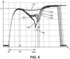
- FIG 4 schematically represents the temporal evolution of the electric current flowing in the electromagnetic actuator 1 when the latter is controlled, during an accelerated aging test of a switching device 30.
- the figure 4 illustrates the evolution of the parameters ta and i1 during this accelerated aging test.
- Such a type of test is carried out under severe conditions compared to normal use of the switching device, for example with a higher temperature and a more corrosive atmosphere than in normal conditions.
- Curve G2 corresponds to the initial state at the start of the test
- curves G3, G4, ..., G7 correspond to the state after increasing test durations.
- the time tmin corresponding to the end of movement of the magnetic core 3, gradually shifts towards increasingly higher values.
- the direction of variation is highlighted by the arrow fe. This shift reflects an increasingly difficult movement of the mechanical parts of the switching device.
- the current is almost constant, which shows that the magnetic core is almost blocked in its movement. Such a state corresponds to a failure of the switching device.
- the average value Avg may be a rolling average calculated from the M values corresponding to the M actuations preceding the current actuation, and comprising a number of values equal to the predetermined number M of actuations.
- the current actuation is not included in the subset of values taken into account for the calculation of the average value. This subset comprises M values.
- the statistical parameter D representative of a fluctuation of the values of the set E of values of the polynomial of the determined reaction time ta and of the determined quantity i1 comprises a standard deviation of the values of the polynomial of the determined reaction time ta and of the determined quantity i1 determined for a set of actuations of the switching device 30 carried out under reference conditions corresponding to a new state of the switching device 30.
- the standard deviation of a set of samples is defined as the magnitude equal to the square root of the variance of that set of samples.
- the variance is itself defined by the mathematical expectation of the square of the deviations from the mean, or the quadratic mean of the deviations between the values of the set of samples and the mean of those values.
- the set of actuations of the switching device 30 carried out under reference conditions comprises for example 20 successive actuations of the switching device.
- the proposed method thus includes a calibration phase allowing the quantification of the nominal variations in the value of the reaction time polynomial. determined ta and the quantity i1 representative of the current flowing in the electromagnetic actuator 1 when the switching device 30 is actuated. These nominal variations correspond to the variations observed in a reference state in which the switching device 30 does not exhibit any degradation.
- the reference state corresponds, for example, to a new state of the switching device 30.
- the new state is understood to mean a period starting with the first actuation of the switching device, lasting a predetermined maximum duration and comprising a predetermined maximum number of actuations.
- the new state corresponds to a time period.
- the values acquired under these reference conditions make it possible to determine the nominal variability of the quantity equal to the polynomial of the determined reaction time ta and of the determined quantity i1.
- This variability is here characterized by the mathematical quantity equal to the standard deviation of the quantity equal to the polynomial of the determined reaction time ta and of the determined quantity i1, determined for the actuations corresponding to the calibration phase.
- the proposed method comprises a measurement phase in which the variations of the value of the polynomial of the determined reaction time ta and of the quantity i1 representative of the current flowing in the electromagnetic actuator 1 are analyzed.
- the measurement phase follows the calibration phase.
- the measuring phase is, for example, carried out throughout the duration of use of the switching device 30.
- FIG. 5 illustrates the values of the quantity P equal to the polynomial of the determined reaction time ta and of the determined quantity i1, for different actuations.
- Part A shows the measurements taken at a first time t1.
- Part B of the figure shows the measurements taken at a second time t2, which is after t1.
- the measurement points framed by the box designated by J0 are those carried out under reference conditions corresponding to a new state of the switching device 30. To simplify the figure, only 7 measurement points have been shown. It can be noted that the dispersion of the values of the quantity P is low.
- the sign Ec0 designates the standard deviation of the values corresponding to the set of actuations of the switching device 30 carried out under reference conditions, and taken into account for the calibration phase. In the example shown, the values taken into account for determining the reference standard deviation correspond to consecutive actuations of the electromagnetic actuator 1. It is also possible that the values do not correspond to consecutive actuations, i.e. some actuations may not be taken into account.
- the measurement points framed by the box designated by J1 are the points used at time t1 for the measurement phase.
- the value P n determined at time t1 is the current value at time t1, that is to say the most recent value, corresponding to the most recent command of the electromagnetic actuator 1.
- the dotted horizontal line indicates the average value avg1 of the values taken into account, i.e. those present in frame J1.
- the arrow designated by d1 illustrates the difference d1 between the current value P n and the average value avg1 calculated on the example of the figure 5 on the 10 measurement points preceding the current measurement.
- the measurement points framed by the box designated by J2 are the points used at time t2 for the measurement phase.
- the value determined at time t2 is the current value at time t2, i.e. the most recent value.
- 4 new measurements have been acquired, and the 4 oldest values of frame J1 are not used at time t2 and are not part of frame J2.
- the dotted horizontal line indicates the average value avg2 of the values taken into account, i.e. those present in frame J2.
- the arrow designated by d2 illustrates the deviation d2 between the current value P n+4 and the average value avg2.
- the proposed statistical parameter D allows a robust detection of a degradation of the electromagnetic actuator 1, while being simple to implement.
- the necessary calculations are easily achievable in real time, which allows a detection also in real time of the presence of a degradation.
- K is a number of actuations carried out under reference conditions corresponding to a new state of the switching device 30. That is to say that K is the number of actuations taken into account for the initial calibration
- a degradation of the electromagnetic actuator 1 is determined when the absolute value of the statistical parameter D representative of a fluctuation of the polynomial of the determined reaction time ta and of the determined quantity i1 is greater than a first positive predetermined threshold S1.
- the absolute value of a given number is its numerical value without regard to its sign. If a number is positive, its absolute value is thus equal to that number. If a number is negative, its absolute value is equal to the opposite of that number.
- a degradation is said to be determined when a degradation is detected.
- the value chosen for the first positive predetermined threshold S1 makes it possible to adjust the sensitivity of the proposed detection method.
- the first predetermined positive threshold S1 is for example between 2 and 3. The closer the chosen threshold is to 1, the more sensitive the fault detection will be, i.e. a small deviation from the reference conditions will be interpreted as the appearance of degradation.
- an absence of degradation of the electromagnetic actuator 1 is determined when the absolute value of the statistical parameter D representative of a fluctuation of the polynomial of the determined reaction time ta and of the determined quantity i1 is less than or equal to the first positive predetermined threshold S1.
- a low value of the absolute value of the statistical parameter D indicates a small deviation between the current behavior of the electromagnetic actuator 1 and its behavior in the new state, indicates an operating state close to the new state. An absence of degradation can thus be confirmed.
- the degradation of the electromagnetic actuator 1 is classified into a first type of degradation, called minor degradation, when the absolute value of the statistical parameter D representative of a fluctuation of the polynomial of the determined reaction time ta and of the determined quantity i1 is greater than a first predetermined positive threshold S1 and less than a second predetermined positive threshold S2.
- the second predetermined positive threshold S2 is for example between 4 and 5.
- the degradation of the electromagnetic actuator 1 is classified into a second type of degradation, called major degradation, when the absolute value of the statistical parameter D representative of a fluctuation of the polynomial of the determined reaction time ta and of the determined quantity i1 is greater than the second positive predetermined threshold S2.
- the proposed method can be implemented without performing a direct calculation of the absolute value of the statistical parameter D.
- the determined value of the statistical parameter D can be compared on the one hand to the threshold values S1, S2, which are positive, and on the other hand to the opposite -S1, -S2 of these threshold values. A possible degradation can be determined on the basis of this double comparison.
- the statistical parameter D used thus allows a quantification of the severity of the degradation, and not only a determination of the presence or absence of a degradation.
- the operators of the electrical circuit 50 on which the switching device is used can thus follow the evolution of the device over time, and react accordingly.
- the detection method may comprise a step of emitting an alert signal in response to a determination of degradation of the electromagnetic actuator 1.
- the warning signal can be, for example, a code stored in an electronic control unit.
- the alert signal may be the lighting of a warning light.
- the alert signal may be a display of a message on a control screen.
- Other types of alert are of course possible.
- the alert signal issued may be different when the detected degradation is a so-called minor degradation and when the detected degradation is a so-called major degradation.
- the alert signal emitted allows users to plan and carry out a maintenance operation or replacement of the degraded switching device, in order to correct the diagnosed problem.
- No alert signal is emitted when no degradation has been determined. In other words, no alert is emitted when the proposed method indicates that the electromagnetic actuator 1 is free of degradation.
Landscapes
- Physics & Mathematics (AREA)
- General Physics & Mathematics (AREA)
- Engineering & Computer Science (AREA)
- Theoretical Computer Science (AREA)
- Electromagnets (AREA)
- Testing Electric Properties And Detecting Electric Faults (AREA)
- Reciprocating, Oscillating Or Vibrating Motors (AREA)
- Electronic Switches (AREA)
Applications Claiming Priority (1)
| Application Number | Priority Date | Filing Date | Title |
|---|---|---|---|
| FR2307588A FR3151133B1 (fr) | 2023-07-13 | 2023-07-13 | Procédé de détection d’une dégradation d'un appareil de commutation comprenant un actionneur électromagnétique |
Publications (3)
| Publication Number | Publication Date |
|---|---|
| EP4492422A1 true EP4492422A1 (de) | 2025-01-15 |
| EP4492422B1 EP4492422B1 (de) | 2025-11-12 |
| EP4492422C0 EP4492422C0 (de) | 2025-11-12 |
Family
ID=88778878
Family Applications (1)
| Application Number | Title | Priority Date | Filing Date |
|---|---|---|---|
| EP24186903.1A Active EP4492422B1 (de) | 2023-07-13 | 2024-07-05 | Verfahren zur erkennung einer verschlechterung einer schaltvorrichtung mit einem elektromagnetischen aktuator |
Country Status (5)
| Country | Link |
|---|---|
| US (1) | US20250020720A1 (de) |
| EP (1) | EP4492422B1 (de) |
| CN (1) | CN119310447A (de) |
| ES (1) | ES3061752T3 (de) |
| FR (1) | FR3151133B1 (de) |
Citations (3)
| Publication number | Priority date | Publication date | Assignee | Title |
|---|---|---|---|---|
| US7692522B2 (en) * | 2004-12-23 | 2010-04-06 | Siemens Aktiengesellschaft | Method and device for the safe operation of a switching device |
| US20170287666A1 (en) * | 2014-09-02 | 2017-10-05 | Mitsubishi Electric Corporation | Circuit breaker characteristic monitoring device |
| US20230025832A1 (en) * | 2021-07-23 | 2023-01-26 | Schneider Electric Industries Sas | Switching device for a medium voltage electrical circuit |
Family Cites Families (3)
| Publication number | Priority date | Publication date | Assignee | Title |
|---|---|---|---|---|
| US20050047045A1 (en) * | 2003-08-29 | 2005-03-03 | Puskar Michael P. | Circuit breaker and trip unit employing multiple function time selector switch |
| US20090154046A1 (en) * | 2007-12-18 | 2009-06-18 | Robinson Judy A | Trip unit and electrical switching apparatus including a movable indicator to indicate selection of an arc reduction maintenance system current condition |
| US9864008B2 (en) * | 2014-03-31 | 2018-01-09 | Schweitzer Engineering Laboratories, Inc. | Electric power system circuit breaker trip diagnostic |
-
2023
- 2023-07-13 FR FR2307588A patent/FR3151133B1/fr active Active
-
2024
- 2024-07-05 EP EP24186903.1A patent/EP4492422B1/de active Active
- 2024-07-05 ES ES24186903T patent/ES3061752T3/es active Active
- 2024-07-11 CN CN202410926284.0A patent/CN119310447A/zh active Pending
- 2024-07-11 US US18/769,602 patent/US20250020720A1/en active Pending
Patent Citations (3)
| Publication number | Priority date | Publication date | Assignee | Title |
|---|---|---|---|---|
| US7692522B2 (en) * | 2004-12-23 | 2010-04-06 | Siemens Aktiengesellschaft | Method and device for the safe operation of a switching device |
| US20170287666A1 (en) * | 2014-09-02 | 2017-10-05 | Mitsubishi Electric Corporation | Circuit breaker characteristic monitoring device |
| US20230025832A1 (en) * | 2021-07-23 | 2023-01-26 | Schneider Electric Industries Sas | Switching device for a medium voltage electrical circuit |
Also Published As
| Publication number | Publication date |
|---|---|
| CN119310447A (zh) | 2025-01-14 |
| EP4492422B1 (de) | 2025-11-12 |
| EP4492422C0 (de) | 2025-11-12 |
| US20250020720A1 (en) | 2025-01-16 |
| FR3151133B1 (fr) | 2025-06-13 |
| ES3061752T3 (en) | 2026-04-07 |
| FR3151133A1 (fr) | 2025-01-17 |
Similar Documents
| Publication | Publication Date | Title |
|---|---|---|
| EP2584575B1 (de) | Verfahren zur Diagnose eines Betriebszustands für einen Schütz und Schütz zur Implementierung dieses Verfahrens | |
| EP2254136B1 (de) | Apparat zur Bestimmung der Integrität von Kontakten, die durch die Variation der Wellendrehung der Pole gedrückt sind und sein Herstellungsverfahren | |
| FR2834120A1 (fr) | Procede pour determiner l'usure des contacts d'un appareil interrupteur | |
| Kang et al. | Noninvasive on-line condition monitoring of on load tap changers | |
| EP1042679B1 (de) | Elektronische überwachungsschaltung für elektrische spannung | |
| FR3010584A1 (fr) | Appareil auxiliaire pour disjoncteur electrique, systeme electrique comportant un disjoncteur et un tel appareil auxiliaire et procede de determination d'une cause de l'ouverture du disjoncteur a l'aide d'un tel appareil auxiliaire | |
| EP4123676B1 (de) | Vorrichtung zur unterbrechung eines mittelspannungsstromkreises | |
| EP4492422B1 (de) | Verfahren zur erkennung einer verschlechterung einer schaltvorrichtung mit einem elektromagnetischen aktuator | |
| EP2682972B1 (de) | Vorrichtung zur Erkennung des offenen oder geschlossenen Zustands eines Schalters, und Schutz-Relaisüberwachungsvorrichtung des entsprechenden Transformators | |
| EP3936878A1 (de) | Verfahren zur bestimmung einer alterungsfunktion eines akkumulators | |
| EP4343289A1 (de) | Verfahren und system zur bestimmung einer auslösedomäne einer elektrischen schaltvorrichtung | |
| EP4492423B1 (de) | Verfahren zur erkennung einer verschlechterung einer schaltvorrichtung | |
| EP4016578B1 (de) | Diagnosevorrichtung für eine schaltung, entsprechendes schaltgerät und diagnoseverfahren | |
| FR2940509A1 (fr) | Appareil electrique interrupteur a fonctionnement optimise | |
| EP2320443A2 (de) | Vorrichtung zur Bestimmung des Kontaktabbrands von elektrischen Schaltgeräten | |
| EP4170362A1 (de) | Verfahren zur erkennung abnormaler ereignisse in einem elektrischen leiter eines elektrischen mittelspannungsgeräts | |
| FR2689677A1 (fr) | Dispositif de contrôle de l'état d'un fusible multibrins. | |
| WO2000063932A1 (fr) | Systeme de diagnostic de contact electrique a deplacement mecanique | |
| US11177090B2 (en) | Determining a state of a switching unit | |
| EP4004354B1 (de) | Automatische erkennung einer hardware-konfiguration eines gerätes an bord eines flugzeugs | |
| CN121500087B (zh) | 一种城轨列车继电器状态在线监测方法及系统 | |
| EP2603922A1 (de) | Verfahren und vorrichtung zur steuerung der bewegung eines beweglichen teils eines trennschalters | |
| EP3594976B1 (de) | Verfahren zur erkennung eines unzureichenden kontaktdrucks in einem stromunterbrechungsgerät, vorrichtung zur umsetzung dieses verfahrens und diese vorrichtung umfassendes stromunterbrechungsgerät | |
| EP4564035A1 (de) | Verfahren und vorrichtung zur erkennung eines fehlers einer bleibatterie | |
| FR3161789A1 (fr) | Contacteur électrique comprenant au moins un identifiant unique digitalisé, installation électrique comportant au moins un tel contacteur électrique, procédé de maintenance d’une telle installation électrique |
Legal Events
| Date | Code | Title | Description |
|---|---|---|---|
| PUAI | Public reference made under article 153(3) epc to a published international application that has entered the european phase |
Free format text: ORIGINAL CODE: 0009012 |
|
| STAA | Information on the status of an ep patent application or granted ep patent |
Free format text: STATUS: THE APPLICATION HAS BEEN PUBLISHED |
|
| AK | Designated contracting states |
Kind code of ref document: A1 Designated state(s): AL AT BE BG CH CY CZ DE DK EE ES FI FR GB GR HR HU IE IS IT LI LT LU LV MC ME MK MT NL NO PL PT RO RS SE SI SK SM TR |
|
| STAA | Information on the status of an ep patent application or granted ep patent |
Free format text: STATUS: REQUEST FOR EXAMINATION WAS MADE |
|
| 17P | Request for examination filed |
Effective date: 20250326 |
|
| GRAP | Despatch of communication of intention to grant a patent |
Free format text: ORIGINAL CODE: EPIDOSNIGR1 |
|
| STAA | Information on the status of an ep patent application or granted ep patent |
Free format text: STATUS: GRANT OF PATENT IS INTENDED |
|
| INTG | Intention to grant announced |
Effective date: 20250717 |
|
| GRAS | Grant fee paid |
Free format text: ORIGINAL CODE: EPIDOSNIGR3 |
|
| GRAA | (expected) grant |
Free format text: ORIGINAL CODE: 0009210 |
|
| STAA | Information on the status of an ep patent application or granted ep patent |
Free format text: STATUS: THE PATENT HAS BEEN GRANTED |
|
| AK | Designated contracting states |
Kind code of ref document: B1 Designated state(s): AL AT BE BG CH CY CZ DE DK EE ES FI FR GB GR HR HU IE IS IT LI LT LU LV MC ME MK MT NL NO PL PT RO RS SE SI SK SM TR |
|
| REG | Reference to a national code |
Ref country code: CH Ref legal event code: F10 Free format text: ST27 STATUS EVENT CODE: U-0-0-F10-F00 (AS PROVIDED BY THE NATIONAL OFFICE) Effective date: 20251112 Ref country code: GB Ref legal event code: FG4D Free format text: NOT ENGLISH |
|
| REG | Reference to a national code |
Ref country code: IE Ref legal event code: FG4D Free format text: LANGUAGE OF EP DOCUMENT: FRENCH |
|
| U01 | Request for unitary effect filed |
Effective date: 20251117 |
|
| U07 | Unitary effect registered |
Designated state(s): AT BE BG DE DK EE FI FR IT LT LU LV MT NL PT RO SE SI Effective date: 20251121 |
|
| REG | Reference to a national code |
Ref country code: ES Ref legal event code: FG2A Ref document number: 3061752 Country of ref document: ES Kind code of ref document: T3 Effective date: 20260407 |
|
| PG25 | Lapsed in a contracting state [announced via postgrant information from national office to epo] |
Ref country code: NO Free format text: LAPSE BECAUSE OF FAILURE TO SUBMIT A TRANSLATION OF THE DESCRIPTION OR TO PAY THE FEE WITHIN THE PRESCRIBED TIME-LIMIT Effective date: 20260212 |
|
| PG25 | Lapsed in a contracting state [announced via postgrant information from national office to epo] |
Ref country code: HR Free format text: LAPSE BECAUSE OF FAILURE TO SUBMIT A TRANSLATION OF THE DESCRIPTION OR TO PAY THE FEE WITHIN THE PRESCRIBED TIME-LIMIT Effective date: 20251112 |
|
| PG25 | Lapsed in a contracting state [announced via postgrant information from national office to epo] |
Ref country code: RS Free format text: LAPSE BECAUSE OF FAILURE TO SUBMIT A TRANSLATION OF THE DESCRIPTION OR TO PAY THE FEE WITHIN THE PRESCRIBED TIME-LIMIT Effective date: 20260212 |
|
| PG25 | Lapsed in a contracting state [announced via postgrant information from national office to epo] |
Ref country code: IS Free format text: LAPSE BECAUSE OF FAILURE TO SUBMIT A TRANSLATION OF THE DESCRIPTION OR TO PAY THE FEE WITHIN THE PRESCRIBED TIME-LIMIT Effective date: 20260312 |
|
| PG25 | Lapsed in a contracting state [announced via postgrant information from national office to epo] |
Ref country code: PL Free format text: LAPSE BECAUSE OF FAILURE TO SUBMIT A TRANSLATION OF THE DESCRIPTION OR TO PAY THE FEE WITHIN THE PRESCRIBED TIME-LIMIT Effective date: 20251112 |