EP4494877A1 - Dispositif d'impression - Google Patents
Dispositif d'impression Download PDFInfo
- Publication number
- EP4494877A1 EP4494877A1 EP24184177.4A EP24184177A EP4494877A1 EP 4494877 A1 EP4494877 A1 EP 4494877A1 EP 24184177 A EP24184177 A EP 24184177A EP 4494877 A1 EP4494877 A1 EP 4494877A1
- Authority
- EP
- European Patent Office
- Prior art keywords
- ink
- depth
- intermediate element
- printing plate
- width
- Prior art date
- Legal status (The legal status is an assumption and is not a legal conclusion. Google has not performed a legal analysis and makes no representation as to the accuracy of the status listed.)
- Pending
Links
Images




Classifications
-
- B—PERFORMING OPERATIONS; TRANSPORTING
- B41—PRINTING; LINING MACHINES; TYPEWRITERS; STAMPS
- B41F—PRINTING MACHINES OR PRESSES
- B41F11/00—Rotary presses or machines having forme cylinders carrying a plurality of printing surfaces, or for performing letterpress, lithographic, or intaglio processes selectively or in combination
- B41F11/02—Rotary presses or machines having forme cylinders carrying a plurality of printing surfaces, or for performing letterpress, lithographic, or intaglio processes selectively or in combination for securities
-
- B—PERFORMING OPERATIONS; TRANSPORTING
- B41—PRINTING; LINING MACHINES; TYPEWRITERS; STAMPS
- B41F—PRINTING MACHINES OR PRESSES
- B41F13/00—Common details of rotary presses or machines
- B41F13/08—Cylinders
- B41F13/193—Transfer cylinders; Offset cylinders
-
- B—PERFORMING OPERATIONS; TRANSPORTING
- B41—PRINTING; LINING MACHINES; TYPEWRITERS; STAMPS
- B41F—PRINTING MACHINES OR PRESSES
- B41F31/00—Inking arrangements or devices
- B41F31/18—Inking arrangements or devices for inking selected parts of printing formes
-
- B—PERFORMING OPERATIONS; TRANSPORTING
- B41—PRINTING; LINING MACHINES; TYPEWRITERS; STAMPS
- B41F—PRINTING MACHINES OR PRESSES
- B41F31/00—Inking arrangements or devices
- B41F31/20—Ink-removing or collecting devices
-
- B—PERFORMING OPERATIONS; TRANSPORTING
- B41—PRINTING; LINING MACHINES; TYPEWRITERS; STAMPS
- B41F—PRINTING MACHINES OR PRESSES
- B41F31/00—Inking arrangements or devices
- B41F31/26—Construction of inking rollers
-
- B—PERFORMING OPERATIONS; TRANSPORTING
- B41—PRINTING; LINING MACHINES; TYPEWRITERS; STAMPS
- B41F—PRINTING MACHINES OR PRESSES
- B41F5/00—Rotary letterpress machines
- B41F5/22—Rotary letterpress machines for indirect printing
-
- B—PERFORMING OPERATIONS; TRANSPORTING
- B41—PRINTING; LINING MACHINES; TYPEWRITERS; STAMPS
- B41F—PRINTING MACHINES OR PRESSES
- B41F5/00—Rotary letterpress machines
- B41F5/24—Rotary letterpress machines for flexographic printing
-
- B—PERFORMING OPERATIONS; TRANSPORTING
- B41—PRINTING; LINING MACHINES; TYPEWRITERS; STAMPS
- B41F—PRINTING MACHINES OR PRESSES
- B41F9/00—Rotary intaglio printing presses
- B41F9/01—Rotary intaglio printing presses for indirect printing
-
- B—PERFORMING OPERATIONS; TRANSPORTING
- B41—PRINTING; LINING MACHINES; TYPEWRITERS; STAMPS
- B41F—PRINTING MACHINES OR PRESSES
- B41F9/00—Rotary intaglio printing presses
- B41F9/02—Rotary intaglio printing presses for multicolour printing
-
- B—PERFORMING OPERATIONS; TRANSPORTING
- B41—PRINTING; LINING MACHINES; TYPEWRITERS; STAMPS
- B41F—PRINTING MACHINES OR PRESSES
- B41F9/00—Rotary intaglio printing presses
- B41F9/06—Details
- B41F9/08—Wiping mechanisms
- B41F9/10—Doctors, scrapers, or like devices
-
- B—PERFORMING OPERATIONS; TRANSPORTING
- B41—PRINTING; LINING MACHINES; TYPEWRITERS; STAMPS
- B41F—PRINTING MACHINES OR PRESSES
- B41F30/00—Devices for attaching coverings or make-ready devices; Guiding devices for coverings
- B41F30/04—Devices for attaching coverings or make-ready devices; Guiding devices for coverings attaching to transfer cylinders
-
- B—PERFORMING OPERATIONS; TRANSPORTING
- B41—PRINTING; LINING MACHINES; TYPEWRITERS; STAMPS
- B41F—PRINTING MACHINES OR PRESSES
- B41F9/00—Rotary intaglio printing presses
- B41F9/06—Details
- B41F9/08—Wiping mechanisms
- B41F9/10—Doctors, scrapers, or like devices
- B41F9/1018—Doctors, scrapers, or like devices using a wiping cylinder
-
- B—PERFORMING OPERATIONS; TRANSPORTING
- B41—PRINTING; LINING MACHINES; TYPEWRITERS; STAMPS
- B41M—PRINTING, DUPLICATING, MARKING, OR COPYING PROCESSES; COLOUR PRINTING
- B41M1/00—Inking and printing with a printer's forme
- B41M1/10—Intaglio printing ; Gravure printing
-
- B—PERFORMING OPERATIONS; TRANSPORTING
- B41—PRINTING; LINING MACHINES; TYPEWRITERS; STAMPS
- B41M—PRINTING, DUPLICATING, MARKING, OR COPYING PROCESSES; COLOUR PRINTING
- B41M3/00—Printing processes to produce particular kinds of printed work, e.g. patterns
- B41M3/14—Security printing
-
- B—PERFORMING OPERATIONS; TRANSPORTING
- B41—PRINTING; LINING MACHINES; TYPEWRITERS; STAMPS
- B41N—PRINTING PLATES OR FOILS; MATERIALS FOR SURFACES USED IN PRINTING MACHINES FOR PRINTING, INKING, DAMPING, OR THE LIKE; PREPARING SUCH SURFACES FOR USE AND CONSERVING THEM
- B41N10/00—Blankets or like coverings; Coverings for wipers for intaglio printing
- B41N10/02—Blanket structure
-
- B—PERFORMING OPERATIONS; TRANSPORTING
- B41—PRINTING; LINING MACHINES; TYPEWRITERS; STAMPS
- B41N—PRINTING PLATES OR FOILS; MATERIALS FOR SURFACES USED IN PRINTING MACHINES FOR PRINTING, INKING, DAMPING, OR THE LIKE; PREPARING SUCH SURFACES FOR USE AND CONSERVING THEM
- B41N10/00—Blankets or like coverings; Coverings for wipers for intaglio printing
- B41N10/02—Blanket structure
- B41N10/04—Blanket structure multi-layer
-
- B—PERFORMING OPERATIONS; TRANSPORTING
- B41—PRINTING; LINING MACHINES; TYPEWRITERS; STAMPS
- B41N—PRINTING PLATES OR FOILS; MATERIALS FOR SURFACES USED IN PRINTING MACHINES FOR PRINTING, INKING, DAMPING, OR THE LIKE; PREPARING SUCH SURFACES FOR USE AND CONSERVING THEM
- B41N7/00—Shells for rollers of printing machines
-
- B—PERFORMING OPERATIONS; TRANSPORTING
- B41—PRINTING; LINING MACHINES; TYPEWRITERS; STAMPS
- B41N—PRINTING PLATES OR FOILS; MATERIALS FOR SURFACES USED IN PRINTING MACHINES FOR PRINTING, INKING, DAMPING, OR THE LIKE; PREPARING SUCH SURFACES FOR USE AND CONSERVING THEM
- B41N7/00—Shells for rollers of printing machines
- B41N7/06—Shells for rollers of printing machines for inking rollers
-
- B—PERFORMING OPERATIONS; TRANSPORTING
- B42—BOOKBINDING; ALBUMS; FILES; SPECIAL PRINTED MATTER
- B42D—BOOKS; BOOK COVERS; LOOSE LEAVES; PRINTED MATTER CHARACTERISED BY IDENTIFICATION OR SECURITY FEATURES; PRINTED MATTER OF SPECIAL FORMAT OR STYLE NOT OTHERWISE PROVIDED FOR; DEVICES FOR USE THEREWITH AND NOT OTHERWISE PROVIDED FOR; MOVABLE-STRIP WRITING OR READING APPARATUS
- B42D25/00—Information-bearing cards or sheet-like structures characterised by identification or security features; Manufacture thereof
- B42D25/20—Information-bearing cards or sheet-like structures characterised by identification or security features; Manufacture thereof characterised by a particular use or purpose
- B42D25/29—Securities; Bank notes
Definitions
- the invention relates to a printing device comprising at least one inking unit for providing an ink, which is followed by at least one intermediate element which is supplied with the ink from its associated inking unit.
- the device further comprises at least one printing plate with image areas arranged therein, which is designed to receive the ink from the intermediate element, and at least one doctor blade which is designed to wipe off excess ink from the printing plate.
- the elements of the printing device described at the beginning relate in particular to the field of intaglio printing for sheet-fed or web-fed printing of securities, particularly banknotes.
- Intaglio printing inherently offers protection against counterfeiting, as the effort involved and the associated costs represent a first barrier to reworking securities.
- Securities are also equipped with certain security features. For example, different colors or highly specialized colors that are difficult to obtain on the market are incorporated to make reworking even more difficult.
- the production of securities is not limited to the intaglio printing process. Using the example of a euro banknote, the offset printing process in combination with the intaglio printing process is used for its background and main motifs.
- Various holograms and numbers with color changes in the banknotes are produced using screen printing.
- a conventional intaglio printing machine for the production of securities according to the state of the art is shown in the DE 698 01 184 T2
- This intaglio printing machine has a plate cylinder around the circumference of which at least one printing plate, preferably several printing plates regularly distributed around its circumference, is/are clamped.
- An ink collection cylinder is supplied with ink by ink selection rollers which are arranged next to one another around part of the circumference of the ink collection cylinder and have reliefs which correspond to the inked zones to be printed in different colors and which are in contact with the circumference of the ink collection cylinder.
- the ink collection cylinder transfers the colors applied to its surface to the printing plate(s) of the plate cylinder.
- a wiping cylinder is provided on the circumference of the plate cylinder as a doctor blade which, viewed in the direction of rotation of the plate cylinder, is located behind the ink collection cylinder and removes ink from the surface of the engraved printing plates outside the engraving pits.
- the printing device shown comprises three assemblies I, II, III.
- Assembly II comprises an inking unit and a stencil roller
- assembly I comprises a printing cylinder, a plate cylinder and a wiping cylinder serving as a doctor blade.
- assembly III which has an ink collecting cylinder and can be removed if necessary, so that assembly I connects directly to assembly II.
- the stencil rollers have a relief structure that is matched to the areas of the gravure plates of the plate cylinder that are to be printed.
- the relief structure onto which ink is applied is a zone that is raised compared to the surrounding areas of the stencil rollers.
- the relief structure is formed by cutting away the areas of the material of the stencil roller that surround the relief structure, starting from the outline of the relief structure.
- the present object is achieved by providing a device having the features of claim 1.
- Advantageous embodiments of the invention are set out in the dependent claims, the description and the drawings.
- the printing device comprises at least one inking unit for providing an ink, which is followed by at least one intermediate element, the intermediate element being supplied with the ink by the inking unit; at least one printing plate with image areas arranged therein, which is designed to receive the ink from the intermediate element; and at least one doctor blade which is designed to wipe off excess applied ink from the printing plate.
- the intermediate element has depressions in a color surface which receives the ink in at least one area which is assigned to the image areas, the depressions preferably being arranged in a grid pattern.
- the printing plate can be mounted on a plate cylinder. Several printing plates can also be evenly distributed around the circumference of a plate cylinder.
- the intermediate elements are preferably designed as stencil cylinders.
- the doctor blade is preferably designed as a wiping cylinder.
- the invention offers the advantage of these depressions in the intermediate elements that the depressions absorb more ink than the surrounding ink surface without depressions.
- the ink from the depressions is transferred to the area of the respective image areas of the printing plate.
- ink that is applied to the surrounding ink surface without depressions is also transferred to the printing plate. So that the printing plate only has ink in the image areas, the doctor blade is provided for wiping off the excess ink in order to squeegee the non-image areas, i.e. the non-depressed areas, free of ink.
- the ink that is wiped off in this process cannot usually be returned to the inking unit, which results in a loss of ink.
- the intermediate element without depressions must absorb enough ink to fill all image areas, regardless of how deep or high these image areas are. If the printing plate has a particularly deep image area in just one small area, the entire printing plate must be coated with the same amount of ink, tailored to this one image area, which means that a particularly large amount of ink is scraped off from non-image areas when the plate is doctored off.
- the image quality remains unaffected, whereby according to the invention a printing device is obtained which can print without loss of quality but with lower ink consumption compared to a device without recesses in color selection rollers.
- the application of ink to the printing plate by the intermediate elements can be carried out indirectly by interposing an ink collecting cylinder between the at least one intermediate element and the printing plate, which is applied with ink by the intermediate element, wherein the ink collecting cylinder applies the ink picked up by the intermediate element to the printing plate.
- the surface of the ink collecting cylinder can preferably be covered with a rubber blanket which has depressions arranged in a grid pattern in an ink-absorbing ink surface in at least one area that is assigned to the image areas of the printing plate.
- This embodiment with the depressions provided in the rubber blanket of the ink collecting cylinder offers the same advantages as those described above with reference to the depressions in the intermediate elements.
- the depressions in the rubber blanket of the ink collecting cylinder can be designed in addition to the depressions in the intermediate element.
- the depressions in the ink surface of the rubber blanket assigned to the image areas of the printing plate are provided as an alternative to the depressions in the at least one intermediate element. The advantage of reduced ink consumption is also retained in this way.
- the application of ink to the printing plate through the intermediate elements can be done directly by having at least one intermediate element in direct contact with the printing plate and applying ink to the printing plate.
- At least one of the depressions between a low point and the paint surface is provided with a single-stage or multi-stage bevel and/or with a rounding. This provides the advantage that paint adhesion in the depressions is reduced.
- the depressions in the color surface of the preferred raster pattern can be surrounded by a border. This provides the advantage that several adjacent areas with different raster patterns and/or depressions are separated from one another. This can improve the quality of the print motif.
- the invention proposes that at least the surface of the intermediate element and/or optionally the rubber blanket of the ink collecting cylinder be made of an elastomer or rubber. This provides the advantage that an exact ink transfer to the printing plate or to another downstream element is made possible.
- At least the surface of the intermediate element and/or optionally the rubber blanket of the ink collecting cylinder is made of ethylene-propylene-diene (monomer) rubber (EPDM) or of acrylonitrile-butadiene rubber provided because it allows precisely dimensioned recesses to be produced that retain their shape even after prolonged use.
- EPDM ethylene-propylene-diene
- acrylonitrile-butadiene rubber provided because it allows precisely dimensioned recesses to be produced that retain their shape even after prolonged use.
- the surface of the intermediate element and/or, if applicable, the rubber blanket of the ink collecting cylinder is colored black, because this provides much more accurate results when the depressions are formed by a laser.
- the depressions in the ink surface of the intermediate element and/or optionally the rubber blanket of the ink collecting cylinder can be formed by lasering and/or by plasma bombardment of the intermediate element.
- lasering is expedient in order to form defined and repeatable depressions.
- the printing plate can be that of a gravure printing process, with the image areas of the printing plate lying deeper than the non-image areas.
- the deeper image areas prevent a high loss of ink when the printing plate is doctored off.
- the width of the at least one recess is between 500 ⁇ m and 1100 ⁇ m.
- the intermediate element can be that of a flexographic printing process, wherein the intermediate element is positioned upstream of an anilox roller, and wherein the doctor blade wipes off excess ink from the intermediate element and/or from the anilox roller.
- the anilox roller should not be confused with the printing plate of a gravure printing process.
- the anilox roller also has so-called cells. However, these cells do not form image areas like the printing plate of the gravure printing process.
- the anilox roller of the flexographic printing process is a so-called upstream roller, which indirectly transfers the ink from an inking unit to a cliché.
- the cliché can also be understood as a printing plate.
- the cliché is usually made of rubber, and can also be called a flexographic cliché, which defines this indirect printing process.
- the intermediate element is that of an offset printing process and the printing plate is a letterpress printing plate.
- This embodiment replaces a conventional offset printing process using mixtures of ink and water.
- the disadvantage of the conventional offset printing process is that a lot of waste is initially produced when setting up the machine until a usable mixture of ink and water is found.
- letterpress printing plates By using letterpress printing plates, a much higher resolution of the print is also achieved, which enables the printing of finer, narrower and more isolated motifs, especially line patterns, than before.
- Fig. 1a shows a printing device 1 according to the invention for carrying out a gravure printing process T with two inking units 2 for providing an ink 3 and an intermediate element downstream of each of the two inking units 2, each intermediate element 4 being supplied with the ink 3 by its associated inking unit 2.
- Inking unit 2 is to be understood as a collection of components for the automatic provision of ink for transfer to the printing plate 5.
- Such an inking unit 2 can comprise several rollers, an immersion tank with ink 3, or ink pumps, and other ink metering devices.
- Inkjet printers can also be understood as inking unit 2.
- the number of inking units 2 in the device is not limited, but one is provided for each of the colors to be printed in inking unit 2.
- the device 1 comprises a printing plate 5 with image areas 6 arranged therein, which is designed to receive the ink 3 from the intermediate element 4.
- the printing plate 5 is arranged on the surface of a plate cylinder, whereby several printing plates 5 can also be arranged regularly around the circumference of the plate cylinder.
- the intermediate elements 4 are designed as stencil cylinders.
- the intermediate elements 4 have depressions 9 in a color surface 8 receiving the ink 3 in at least one area B, which is assigned to the image areas 6 of the printing plate 5, which are arranged in a grid pattern 10, see Fig. 1b .
- the intermediate elements 4 do not transfer the colors 3 directly to the printing plate 5, but rather an ink collecting cylinder OL is interposed between the intermediate element 4 and the printing plate 5.
- the ink collecting cylinder OL In this embodiment, an Orloff cylinder is used, which transfers several different colors 3 simultaneously to the printing plate 5. However, the color collecting cylinder OL is not absolutely necessary to achieve the desired reduction in color loss.
- the ink collecting cylinder OL can be covered on its surface with a rubber blanket GTU, which - analogous to the intermediate elements 4 - has depressions 9' in a color surface 8' receiving the ink 3 in at least one area B', which is assigned to the image areas 6 of the printing plate 5, which are arranged in a grid pattern 10'.
- a surface of such an ink collecting cylinder OL is in Fig. 6a shown schematically.
- the rubber blanket GTU can have incompressible and compressible layers.
- the device 1 further comprises a symbolically represented doctor blade 7, which is designed to wipe off excess applied ink 3 from the printing plate 5.
- the doctor blade 7 is arranged on the circumference of the printing plate 5, which in this illustration is arranged on the circumference of a plate cylinder of a gravure printing process T.
- the doctor blade 7 is preferably designed as a wiping cylinder.
- the doctor blade 7 can be a scraper or a squeegee or a knife-like ground steel belt.
- the task of the doctor blade 7 is to strip the excess ink 3 from the non-image areas NBS of the printing plate 5, so that only the so-called cells or the engravings of the printing plate 5 are filled with the ink 3 that is actually intended for the print motif DM.
- Fig. 6b shows an embodiment of the device 1 which is similar to that of Fig. 1a , with the difference that the intermediate elements 4 provided with the described recesses 8 directly contact the printing plate 5 and thus directly apply ink 3.
- Fig. 6b are the device 1 of Fig. 1a corresponding elements are designated by the same reference numerals and their functions are the same or similar to those of the corresponding elements of Fig. 1a To avoid repetition, reference is made to the above description of the device 1 of Fig. 1 referred to.
- the printing device 1 of the Fig. 1a is assigned to the pressure principle, in which one cylinder is pressed against another cylinder.
- the device 1 is not This printing principle is not limited to this, but can also be applied to surface against surface, the so-called sheet printing, or surface against cylinder.
- the doctor blade 7 is designed as a wiping cylinder which, viewed in the direction of rotation of the printing plate 5 clamped onto the plate cylinder, is located after the ink collecting cylinder OL and cleans the surface of the engraved printing plate 5 outside the image areas 6 of ink 3 and compresses the ink 3 in the image areas 6.
- the printing object DO can be understood to mean different printing materials, such as paper, cardboard, plastic films, metal sheets, glass, ceramics, or skins. In special applications, three-dimensional objects such as cups or bags can also be printed.
- Fig. 1a the printing plate 5 is pressed against the printing object DO by means of a counter-pressure cylinder G. After this step, the printing object DO has the color 3 of the image areas 6 and thus the desired printing motif DM.
- the device of Fig. 1 also have far more color works 2 than shown.
- the device 1 can also be designed in such a way that a second printing plate 5 is clamped onto the counter cylinder G, so that two print motifs DM can be applied to both sides of the print object DO.
- the device 1 can be used in the context of different printing processes. It should be emphasized that a reduction in ink loss is always achieved when ink 3 can no longer be returned to one of the inking units 2 when it is doctored off by a doctor blade 7.
- Fig. 1b is a section of the device 1 of the Fig. 1a shown.
- the step is shown in which the ink 3 has already been transferred from the intermediate element 4 to the ink collecting cylinder OL, ie the ink 3 which was previously held in the depressions 9 has already been transferred from the depressions 9.
- the colour 3 is applied thicker in an area B, which is connected to the image areas 6 that follow later, than on the non-image areas NBS. It should be noted that only through the depressions 9 can the colour 3 be applied over the Non-image areas NBS is particularly thin, whereby the image areas 6 are nevertheless completely filled with ink 3.
- the ink 3 above the non-image areas NBS is doctored off in a further step. It is no longer returned to the inking units 2 because chemical processes in the ink 3 could have already taken place due to air contact, light contact, and/or heat input, and because in the case of the Fig. 1a In the illustrated gravure printing process T with two different inking units 2, the doctored-off ink 3 cannot be returned simply because mixed or superimposed layers of the different inks 3 of the respective inking units 2 were applied to the non-image areas NBS.
- Fig. 2a shows the step of doctoring the Fig. 1a .
- One of the non-image areas NBS has already been freed of ink 3.
- the non-recessed areas are thus doctored free of ink, with ink 3 remaining in the recessed areas in image area 6.
- image areas 6 of printing plate 5 are deeper than non-image areas NBS.
- Image areas 6 are produced by engraving, etching or by a laser.
- the non-image areas NBS would be located deeper than the image areas 6.
- Fig. 2b is another embodiment, similar to the device 1 of Fig. 1a shown.
- the color 3 has not yet been transferred to a directly downstream printing plate 5, which means that no color collecting cylinder OL is required. Instead, the color 3 is transferred directly to the printing plate 5.
- a color collecting cylinder OL is provided which has indentations which are similar in shape to the image areas 6 of a printing plate 5.
- the recesses 9 are completely filled with color 3 and, in addition, the color surface 8 is also covered with color 3. However, color 3 can also only be present in the recesses 9.
- FIG. 2c An enlarged section of one of the recesses 9 is shown in Fig. 2c shown.
- This depression 9 has a spline-like symmetrical rounding 13. It should be mentioned that only a cross-section in the largest extent of the depression 9 is shown.
- the depression 9, or all depressions 9 of a grid pattern 10 can be rotationally symmetrical. This includes polygonal pyramid-like depressions 9, but also n-sided prismatic depressions 9. Dome-shaped, in particular hemispherical depressions 9 can also be provided. It is also conceivable that Differently shaped depressions 9 are formed, even directly next to each other, with different widths 15, depths 14, and also distortions. Distortion can be understood as meaning that in a top view of an outline of a depression 9, for example a parallelogram can be seen.
- depressions 9 are divided into an area B1 and an area B2, which coincide with the respective image locations 6 when the ink 3 is transferred. It should be emphasized that several less deep depressions 9 do not have to be located exclusively over an image location 6 with a low engraving depth GT, as is the case in area B 1. It can be expedient to also provide depressions 9 over non-image locations NBS. This can have the advantage that for a subsequent doctoring step by pushing ink 3 on, ink 3 can be pushed from a non-image location to image locations 6 in order to completely fill all image locations 6. This can be necessary because irregularities in the ink removal repeatedly occur during doctoring due to deformations of the doctor blade 7 or the printing plate 5. Paint splashes can also occur when the doctor blade 7 hits a high point, or non-image point NBS, or paint thickening, whereby a suitable replacement for this repelled paint 3 is provided.
- edges 16 are formed, which form a thickening between the two areas B 1, B 2.
- the marks 16 can, as shown, come into surface contact with the underlying non-image areas NBS, whereby the depressions 9 themselves can also be arranged recessed from the edge 16.
- Fig. 3a shows a top view of a regular grid pattern 10 with depressions 9.
- the grid pattern 10 shown is a section of the Fig. 3b , in which an intermediate element 4 with two areas B1, B2 is shown in a top view.
- the raster pattern 10 is part of the print motif DM, which depicts the number one next to the number zero.
- Each of the numbers is formed in its own area B 1, B2 with different types of depressions 9 in order to leave a different structure, coloring, color effect, and/or embossing in the print object DO.
- the intermediate element 4 is provided as a stencil or stencil cylinder. This means that the print motif DM is raised above a surface of the rest of the stencil, so that only color 3 in the color surface 8, which is raised, is absorbed by a respective inking unit 2.
- the color surface 8 is spaced apart from the print motif DM and is rounded relative to it. This spacing is also called an overlap and can be approximately 10% to 20% larger than the envelope curve of the outermost contour of the respective print motif DM of the respective stencil.
- the colour surface 8 can also have a continuous transition to the underlying surface or stencil surface from which the colour surface 8 protrudes, in the form of a rounding.
- the Cartesian grid pattern 10 shown has depressions 9 with a regular width 15.
- the depressions 9 therefore each have a width 15 and are spaced apart by a width 15.
- the surrounding border 16 also has an extension in the order of magnitude of the width 15.
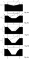
- All described recesses 9 can have the following illustrated embodiments of the Fig. 4a to Fig. 4e and Fig. 5a to Fig. 5e , as well as variations thereof. These depressions 9 are each shown in a cross-sectional view, with their low points 11 lying in an axis of symmetry. The depth 14 is determined by a normal between the low point 11 and the color surface 8. The width 15 of the respective depression 9 lies, seen in cross-section, between two points at which the bevel 12 or rounding 13 begins. This applies to the Fig. 4a to Fig. 5a . The width 15 of the Fig. 5b to Fig. 5e lies between two change points to a smaller curvature in the course of the rounding 13. The color surface 18 can be formed only in a point-like manner between two adjacent depressions 9.
- the depth 14 and the width 15 of the depressions 9 can also be dependent on the respective engraving depth GT of the image areas 6 in the printing plate 5, particularly when it is a question of real halftones being represented on a print motif DM.
- Real halftones are the so-called intermediate tones between black and white.
- real halftones can be achieved by means of the area and depth-variable printing plate 5.
- Other printing processes, such as letterpress, can only approximate halftones by rasterizing full-color image points using a printing screen.
- the depth 14 of the depression 9 is 30 ⁇ m, whereby the width 15 is 600 ⁇ m.
- the engraving in the printing plate 5 can, for example, have an engraving depth GT of 21 ⁇ m to 30 ⁇ m with an engraving width GW of 620 ⁇ m, whereby a maximally saturated black can be obtained with a black color 3 in the print motif DM.
- the engraving depth GT and engraving width GW are shown as examples in Fig. 2c shown.
- the engraving or the image areas 6 can also have roundings and chamfers.
- the image areas 6 can also be jagged several times or be hemispherical.
- the depth 14 of the depression 9 is 50 ⁇ m, with the width being 600 ⁇ m.
- the engraving in the printing plate 5 can, for example, have an engraving depth GT of 30 ⁇ m to 50 ⁇ m with an engraving width GW of 640 ⁇ m, whereby a less saturated black can be obtained in the print motif DM.
- the depth 14 of the depression 9 is 70 ⁇ m, whereby Fig. 4c the width is 600 ⁇ m and in Fig. 5c the width is 80 ⁇ m.
- the engraving in the printing plate 5 can, for example, have an engraving depth GT of 50 ⁇ m to 65 ⁇ m with an engraving width GW of 660 ⁇ m, whereby a gray in the middle between white and black can be obtained in the print motif DM.
- the depth 14 of the recess 9 is 80 ⁇ m, whereby in Fig. 4d the width is 600 ⁇ m and in Fig. 5c the width is 800 ⁇ m.
- the engraving in the printing plate 5 can, for example, have an engraving depth GT of 65 ⁇ m to 75 ⁇ m with an engraving width GW of 670 ⁇ m, whereby a less saturated gray in the middle between white and black can be obtained in the print motif DM.
- the depth 14 of the depression 9 is 100 ⁇ m, whereby in Fig. 4d the width is 600 ⁇ m and in Fig. 5c the width is 1000 ⁇ m.
- the engraving in the printing plate 5 can, for example, have an engraving depth GT of over 75 ⁇ m with an engraving width GW of 680 ⁇ m, whereby a minimally saturated black can be obtained in the print motif DM.
- the aforementioned depths 14, widths 15, engraving depths GT and engraving widths GW are each to be understood with tolerances, in particular with a ⁇ 15% deviation, particularly preferably with a ⁇ 5% deviation. If an engraving depth GT is less than 21 ⁇ m, no recesses 9 can be formed.
- the recesses 9 of the Fig. 4a, Fig. 4b and the Fig. 4c have a single-stage bevel 12.
- the recesses 9 of the Fig. 4d and the Fig. 4e a multi-stage or two-stage bevel 12.
- the Fig. 5a to Fig. 5e each have a rounding to 13.
- depressions 9 have undercuts under the colored surface 8. It is also conceivable that elements protrude from the surface of the depressions 9 in the direction of the colored surface 8, such as rods, or pegs, hemispheres or similar.
- the depressions 9 can also not be rotationally symmetrical. For example, if the depression 9 is cuboid-shaped, bevels 12 can be formed on two opposite edges and roundings 13 on the other two opposite edges.
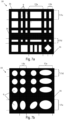
- Fig. 7a shows a grid pattern 10 which has rectangular depressions 9 with irregular dimensions.
- Some of the depressions 9 in the grid pattern 10 shown have, for example, a first width 15a, with a width in Fig. 7a describes a horizontal extension of a depression.
- Other depressions have a second width 15b which is smaller than the first width 15a.
- Some of the depressions 9 have, for example, a first length 15c in the illustrated grid pattern 10, wherein a length in Fig. 7a describes a vertical extension of a depression.
- Other depressions have a second length 15d which is smaller than the first length 15c.
- It is possible for further depressions to have a third length and possibly further lengths.
- the depressions can be rotated, whereby the angle of rotation of an individual depression 9 is independent of the angle of rotation of another depression.
- the edges 16 of different depressions 9 can be of different dimensions.
- Fig. 7b shows a grid pattern 10 which has round depressions 9 with irregular dimensions.
- Some of the depressions 9 in the grid pattern 10 shown have, for example, a first width 15a, with a width in Fig. 7b describes a horizontal extension of a depression.
- Other depressions have a second width 15b which is smaller than the first width 15a.
- Some of the depressions 9 have, for example, a first length 15c in the illustrated grid pattern 10, wherein a length in Fig. 7b describes a vertical extension of a depression.
- Other Depressions have a second length 15d which is smaller than the first length 15c.
- It is possible for further depressions to have a third length and possibly further lengths.
- the depressions can be rotated, whereby the angle of rotation of an individual depression 9 is independent of the angle of rotation of another depression.
- the edges 16 of different depressions 9 can be dimensioned differently.
- the recesses may not only be rectangular and/or round, but may have any geometric shape, including but not limited to triangles, squares, pentagons, hexagons (and other regular and irregular polygons), circles, ellipses, as well as combinations of the aforementioned shapes, etc.
- the corners of the polygon may have rounded edges.
Landscapes
- Engineering & Computer Science (AREA)
- Mechanical Engineering (AREA)
- Printing Methods (AREA)
- Printing Plates And Materials Therefor (AREA)
Applications Claiming Priority (1)
| Application Number | Priority Date | Filing Date | Title |
|---|---|---|---|
| ATA50575/2023A AT527433B1 (de) | 2023-07-18 | 2023-07-18 | Druckvorrichtung |
Publications (1)
| Publication Number | Publication Date |
|---|---|
| EP4494877A1 true EP4494877A1 (fr) | 2025-01-22 |
Family
ID=91670564
Family Applications (1)
| Application Number | Title | Priority Date | Filing Date |
|---|---|---|---|
| EP24184177.4A Pending EP4494877A1 (fr) | 2023-07-18 | 2024-06-25 | Dispositif d'impression |
Country Status (2)
| Country | Link |
|---|---|
| EP (1) | EP4494877A1 (fr) |
| AT (1) | AT527433B1 (fr) |
Citations (12)
| Publication number | Priority date | Publication date | Assignee | Title |
|---|---|---|---|---|
| GB1062461A (en) * | 1963-10-23 | 1967-03-22 | Tech D Impressions Fiduciaires | Improvements in or relating to polychromatic intaglio printing machines |
| US3613578A (en) * | 1969-08-18 | 1971-10-19 | Pamarco Inc | Ink metering roll for use intermediate a fountain roll and a printing roll |
| DE2161331A1 (de) * | 1971-12-10 | 1973-06-20 | Maschf Augsburg Nuernberg Ag | Farbwerk fuer offsetrotations-druckmaschinen |
| EP0089616A2 (fr) * | 1982-03-22 | 1983-09-28 | Foamink Company | Procédé d'impression et de couchage utilisant des compositions moussées à base d'eau et de pigment |
| US4604951A (en) * | 1984-09-03 | 1986-08-12 | Komori Printing Machinery Co., Ltd. | Intaglio printing machine |
| US5282417A (en) | 1992-03-26 | 1994-02-01 | De La Rue Giori S.A. | Intaglio printing machine with direct and color-collect inking |
| DE69801184T2 (de) | 1997-04-14 | 2002-03-14 | Kba-Giori S.A., Lausanne | Tiefdruckmaschine |
| US6467384B1 (en) * | 1999-01-07 | 2002-10-22 | Relief Products Llc | Method and apparatus for cutting a printing blanket |
| DE102008000726A1 (de) * | 2008-03-18 | 2009-09-24 | Manroland Ag | Walze für ein Druckwerk |
| US10022953B2 (en) * | 2013-02-20 | 2018-07-17 | Crown Packaging Technology, Inc. | Can decorator apparatus and method |
| US20220176724A1 (en) * | 2020-12-04 | 2022-06-09 | Levi Acobas Roberto | Blanket or slab for overprint varnishing |
| US11504962B2 (en) * | 2019-02-05 | 2022-11-22 | Koenig & Bauer Ag | Gravure printing units for printing onto substrate, printing press with such a gravure printing unit, ink transfer forme and method for setting up an inking unit cylinder comprised by a gravure printing unit |
Family Cites Families (1)
| Publication number | Priority date | Publication date | Assignee | Title |
|---|---|---|---|---|
| DE102013223826B4 (de) * | 2013-11-21 | 2016-09-22 | Koenig & Bauer Ag | Tiefdruckmaschinen und Druckanlage mit einer Tiefdruckmaschine |
-
2023
- 2023-07-18 AT ATA50575/2023A patent/AT527433B1/de active
-
2024
- 2024-06-25 EP EP24184177.4A patent/EP4494877A1/fr active Pending
Patent Citations (12)
| Publication number | Priority date | Publication date | Assignee | Title |
|---|---|---|---|---|
| GB1062461A (en) * | 1963-10-23 | 1967-03-22 | Tech D Impressions Fiduciaires | Improvements in or relating to polychromatic intaglio printing machines |
| US3613578A (en) * | 1969-08-18 | 1971-10-19 | Pamarco Inc | Ink metering roll for use intermediate a fountain roll and a printing roll |
| DE2161331A1 (de) * | 1971-12-10 | 1973-06-20 | Maschf Augsburg Nuernberg Ag | Farbwerk fuer offsetrotations-druckmaschinen |
| EP0089616A2 (fr) * | 1982-03-22 | 1983-09-28 | Foamink Company | Procédé d'impression et de couchage utilisant des compositions moussées à base d'eau et de pigment |
| US4604951A (en) * | 1984-09-03 | 1986-08-12 | Komori Printing Machinery Co., Ltd. | Intaglio printing machine |
| US5282417A (en) | 1992-03-26 | 1994-02-01 | De La Rue Giori S.A. | Intaglio printing machine with direct and color-collect inking |
| DE69801184T2 (de) | 1997-04-14 | 2002-03-14 | Kba-Giori S.A., Lausanne | Tiefdruckmaschine |
| US6467384B1 (en) * | 1999-01-07 | 2002-10-22 | Relief Products Llc | Method and apparatus for cutting a printing blanket |
| DE102008000726A1 (de) * | 2008-03-18 | 2009-09-24 | Manroland Ag | Walze für ein Druckwerk |
| US10022953B2 (en) * | 2013-02-20 | 2018-07-17 | Crown Packaging Technology, Inc. | Can decorator apparatus and method |
| US11504962B2 (en) * | 2019-02-05 | 2022-11-22 | Koenig & Bauer Ag | Gravure printing units for printing onto substrate, printing press with such a gravure printing unit, ink transfer forme and method for setting up an inking unit cylinder comprised by a gravure printing unit |
| US20220176724A1 (en) * | 2020-12-04 | 2022-06-09 | Levi Acobas Roberto | Blanket or slab for overprint varnishing |
Also Published As
| Publication number | Publication date |
|---|---|
| AT527433B1 (de) | 2025-05-15 |
| AT527433A1 (de) | 2025-02-15 |
Similar Documents
| Publication | Publication Date | Title |
|---|---|---|
| DE69008941T2 (de) | Tiefdruckmaschine zum Drucken von Wertpapieren. | |
| DD209596A5 (de) | Stichdruckmaschine fuer bogen- oder rollendruck von wertpapieren, insbesondere banknoten | |
| DE19731003B4 (de) | Kurzfarbwerk | |
| EP1250226A1 (fr) | Presse pour impression en creux | |
| DE60010354T2 (de) | Gummituch mit variabelen Oberflächeneigenschaften für eine Druckmaschine | |
| EP0844100A2 (fr) | Blanchet d'impression offset | |
| EP0428894B1 (fr) | Procédé de préparation d'une unité d'impression et unité d'impression utilisable pour sa mise en oeuvre | |
| DE2445152A1 (de) | Rotationstiefdruckeinrichtung | |
| AT527433B1 (de) | Druckvorrichtung | |
| DE60020252T2 (de) | Verfahren zum betreiben einer druckeinheit und druckeinheit für eine offset-druckmaschine | |
| EP2095950A1 (fr) | Procédé d'impression en creux à l'aide d'une plaque de pression échangeable | |
| EP4013626B1 (fr) | Élément de sécurité, document de sécurité équipé d'un élément de sécurité ainsi que dispositif et procédé pour produire un élément de sécurité | |
| EP4013615B1 (fr) | Unité d'impression hélio | |
| DE60304362T2 (de) | Tiefdruckplatte | |
| DE10025996C1 (de) | Intaglio-Druckmaschine | |
| DE102016002454A1 (de) | Verfahren und Vorrichtung für den Tiefdruck | |
| DE4328027A1 (de) | Rotationsdruckmaschine zum Herstellen von Zeitungen | |
| DE60306936T2 (de) | Tiefdruckplatte mit tintenhaltestrukturen | |
| DE3821777C2 (fr) | ||
| AT523951B1 (de) | Verfahren zum gravieren einer intaglio-stichtiefdruckplatte | |
| DE102019102856A1 (de) | Druckwerk und Druckmaschine mit mindestens einem Druckwerk sowie Verfahren zum Bedrucken | |
| DE10241739A1 (de) | Mehrfarben-Druckwerk | |
| EP3170665B1 (fr) | Procédé de fonctionnement d'une imprimante comprenant un cylindre tramé | |
| DE2048000C (de) | Druckform für das Hochdruckverfahren | |
| DE19810708C2 (de) | Einrichtung zum Drucken |
Legal Events
| Date | Code | Title | Description |
|---|---|---|---|
| PUAI | Public reference made under article 153(3) epc to a published international application that has entered the european phase |
Free format text: ORIGINAL CODE: 0009012 |
|
| STAA | Information on the status of an ep patent application or granted ep patent |
Free format text: STATUS: THE APPLICATION HAS BEEN PUBLISHED |
|
| AK | Designated contracting states |
Kind code of ref document: A1 Designated state(s): AL AT BE BG CH CY CZ DE DK EE ES FI FR GB GR HR HU IE IS IT LI LT LU LV MC ME MK MT NL NO PL PT RO RS SE SI SK SM TR |
|
| STAA | Information on the status of an ep patent application or granted ep patent |
Free format text: STATUS: REQUEST FOR EXAMINATION WAS MADE |
|
| 17P | Request for examination filed |
Effective date: 20250715 |