EP4496128A2 - Outil de sertissage et procédé de sertissage d'un manchon de sertissage - Google Patents
Outil de sertissage et procédé de sertissage d'un manchon de sertissage Download PDFInfo
- Publication number
- EP4496128A2 EP4496128A2 EP24189197.7A EP24189197A EP4496128A2 EP 4496128 A2 EP4496128 A2 EP 4496128A2 EP 24189197 A EP24189197 A EP 24189197A EP 4496128 A2 EP4496128 A2 EP 4496128A2
- Authority
- EP
- European Patent Office
- Prior art keywords
- crimp
- crimping
- crimp sleeve
- measuring
- sub
- Prior art date
- Legal status (The legal status is an assumption and is not a legal conclusion. Google has not performed a legal analysis and makes no representation as to the accuracy of the status listed.)
- Pending
Links
Images

Classifications
-
- H—ELECTRICITY
- H01—ELECTRIC ELEMENTS
- H01R—ELECTRICALLY-CONDUCTIVE CONNECTIONS; STRUCTURAL ASSOCIATIONS OF A PLURALITY OF MUTUALLY-INSULATED ELECTRICAL CONNECTING ELEMENTS; COUPLING DEVICES; CURRENT COLLECTORS
- H01R43/00—Apparatus or processes specially adapted for manufacturing, assembling, maintaining, or repairing of line connectors or current collectors or for joining electric conductors
- H01R43/04—Apparatus or processes specially adapted for manufacturing, assembling, maintaining, or repairing of line connectors or current collectors or for joining electric conductors for forming connections by deformation, e.g. crimping tool
- H01R43/048—Crimping apparatus or processes
- H01R43/0488—Crimping apparatus or processes with crimp height adjusting means
-
- H—ELECTRICITY
- H01—ELECTRIC ELEMENTS
- H01R—ELECTRICALLY-CONDUCTIVE CONNECTIONS; STRUCTURAL ASSOCIATIONS OF A PLURALITY OF MUTUALLY-INSULATED ELECTRICAL CONNECTING ELEMENTS; COUPLING DEVICES; CURRENT COLLECTORS
- H01R43/00—Apparatus or processes specially adapted for manufacturing, assembling, maintaining, or repairing of line connectors or current collectors or for joining electric conductors
- H01R43/04—Apparatus or processes specially adapted for manufacturing, assembling, maintaining, or repairing of line connectors or current collectors or for joining electric conductors for forming connections by deformation, e.g. crimping tool
- H01R43/042—Hand tools for crimping
-
- H—ELECTRICITY
- H01—ELECTRIC ELEMENTS
- H01R—ELECTRICALLY-CONDUCTIVE CONNECTIONS; STRUCTURAL ASSOCIATIONS OF A PLURALITY OF MUTUALLY-INSULATED ELECTRICAL CONNECTING ELEMENTS; COUPLING DEVICES; CURRENT COLLECTORS
- H01R43/00—Apparatus or processes specially adapted for manufacturing, assembling, maintaining, or repairing of line connectors or current collectors or for joining electric conductors
- H01R43/04—Apparatus or processes specially adapted for manufacturing, assembling, maintaining, or repairing of line connectors or current collectors or for joining electric conductors for forming connections by deformation, e.g. crimping tool
- H01R43/048—Crimping apparatus or processes
-
- H—ELECTRICITY
- H01—ELECTRIC ELEMENTS
- H01R—ELECTRICALLY-CONDUCTIVE CONNECTIONS; STRUCTURAL ASSOCIATIONS OF A PLURALITY OF MUTUALLY-INSULATED ELECTRICAL CONNECTING ELEMENTS; COUPLING DEVICES; CURRENT COLLECTORS
- H01R43/00—Apparatus or processes specially adapted for manufacturing, assembling, maintaining, or repairing of line connectors or current collectors or for joining electric conductors
- H01R43/04—Apparatus or processes specially adapted for manufacturing, assembling, maintaining, or repairing of line connectors or current collectors or for joining electric conductors for forming connections by deformation, e.g. crimping tool
- H01R43/058—Crimping mandrels
- H01R43/0585—Crimping mandrels for crimping apparatus with more than two radially actuated mandrels
-
- H—ELECTRICITY
- H01—ELECTRIC ELEMENTS
- H01R—ELECTRICALLY-CONDUCTIVE CONNECTIONS; STRUCTURAL ASSOCIATIONS OF A PLURALITY OF MUTUALLY-INSULATED ELECTRICAL CONNECTING ELEMENTS; COUPLING DEVICES; CURRENT COLLECTORS
- H01R4/00—Electrically-conductive connections between two or more conductive members in direct contact, i.e. touching one another; Means for effecting or maintaining such contact; Electrically-conductive connections having two or more spaced connecting locations for conductors and using contact members penetrating insulation
- H01R4/10—Electrically-conductive connections between two or more conductive members in direct contact, i.e. touching one another; Means for effecting or maintaining such contact; Electrically-conductive connections having two or more spaced connecting locations for conductors and using contact members penetrating insulation effected solely by twisting, wrapping, bending, crimping, or other permanent deformation
- H01R4/18—Electrically-conductive connections between two or more conductive members in direct contact, i.e. touching one another; Means for effecting or maintaining such contact; Electrically-conductive connections having two or more spaced connecting locations for conductors and using contact members penetrating insulation effected solely by twisting, wrapping, bending, crimping, or other permanent deformation by crimping
- H01R4/20—Electrically-conductive connections between two or more conductive members in direct contact, i.e. touching one another; Means for effecting or maintaining such contact; Electrically-conductive connections having two or more spaced connecting locations for conductors and using contact members penetrating insulation effected solely by twisting, wrapping, bending, crimping, or other permanent deformation by crimping using a crimping sleeve
Definitions
- the invention relates to a crimping tool, in particular for a crimp applicator or a crimping machine, and to an assembled electrical cable.
- the invention also relates to a method for crimping a crimp sleeve and to a method for measuring a crimp dimension for quality assurance.
- the invention relates to a crimp applicator or a crimping machine.
- connection means In the electrical field (electronics, electrical engineering, electrics, electrical power engineering, etc.), a large number of electrical connection means, connection devices, socket, tab, prong, pin and/or hybrid connectors, etc. are known, which are used to transmit electrical currents, voltages, signals and/or data with a wide range of currents, voltages, frequencies and/or data rates.
- connection devices In the low, medium or high voltage and/or current range, and in particular in the automotive sector (low or high voltage range), such connectors must ensure a faultless transmission of electrical power, signals and/or data in warm, possibly hot, contaminated, humid, wet and/or chemically aggressive environments, in the short term and/or permanently. Owing to a wide range of applications, a large number of specially designed connectors are known.
- the electrical terminals of such connectors are often configured as so-called crimp terminals, wherein the relevant crimp terminal is crimped to an electrical cable, such as a stranded electrical cable or an electrical wire etc. of the cable.
- Crimping is a joining process in which, for example, a crimp terminal and a cable are firmly connected to each other by plastic deformation of a crimp sleeve (crimp portion) of the crimp terminal, which can be achieved, for example, by squeezing, flanging, kinking and/or folding. Such a connection is difficult to release and ensures a high level of electrical safety and mechanical stability.
- crimp connections are usually produced using crimping machines (automatic crimping machines, fully automatic crimping machines, automatic cable assembly machines, etc.), which can be used to process crimp terminals, e.g. in the form of strip goods, in order to ensure high productivity and high quality.
- a crimping machine naturally includes a crimping tool, e.g. a crimp applicator of the crimping machine, for producing the crimp connections between the cables and the crimp sleeves of the crimp terminals.
- a crimping tool In order to be able to ensure consistently high quality using a crimping tool, it is necessary to measure the crimp diameter of a crimp sleeve arranged using this crimping tool. This can be carried out, for example, for all relevant crimp sleeves produced (in particular conductor crimp sleeves, insulation crimp sleeves to a certain extent); only for certain selected crimp sleeves (e.g. every 10th, 50th, 100th) or for randomly selected crimp sleeves. -
- Such a crimping tool has, for example, at least one crimping punch and at least one crimping anvil as sub-tools, preferably an even number of, in particular, identical pressing segments, etc. for segmented radial crimping (SRC).
- a crimping tool in particular for a crimp applicator or a crimping machine, for crimping a crimp sleeve, in particular a crimp sleeve of an electrical crimp terminal; by an assembled electrical cable, in particular for the automotive sector; by means of a method for crimping a crimp sleeve of an electrical crimp terminal onto an electrical conductor of an electrical cable; by a method for measuring a crimp dimension, in particular a crimp diameter, for quality assurance; and by means of a crimp applicator or a crimping machine for establishing at least one crimp connection between an electrical crimp terminal and an electrical conductor; according to the independent claims.
- the crimping tool comprises a plurality of sub-tools which can be moved against each other, wherein an individual sub-tool has a mechanically effective sub-crimp surface global to it for partial crimping of the crimp sleeve, and at least one sub-tool, in particular exactly or at least two sub-tools, has a local measuring location insertion device within the relevant global sub-crimp surface, by means of which a measuring location can be incorporated into the crimp sleeve.
- the crimping tool can be configured as an automatic or manual crimping tool.
- the crimping machine comprising the crimping tool can be configured as an automatic crimping machine, a fully automatic crimping machine, an automatic cable assembly machine, etc.
- the crimp sleeve can generally be a portion of a means or device to be crimped, in particular that of an electrical crimping terminal, i.e. a terminal which can be crimped to a cable.
- the crimp sleeve can of course also be configured as an insulation crimp sleeve.
- the crimp sleeve In its non-crimped state, the crimp sleeve can be configured as a crimp sleeve that is closed or open at its circumference.
- An equivalent term to the term 'crimp sleeve' is, for example, 'crimp portion'.
- the crimping tool can be configured as a segmented radial crimping tool with a plurality of sub-tools, in particular even-numbered, sub-tools. In this case, all sub-tools or all sub-tools minus a single sub-tool are arranged to move back and forth in their respective radial direction (star arrangement) of the crimping tool in the crimping tool.
- the crimping tool can, for example, be formed as an SRC crimping tool (SRC: Segmented Radial Crimp).
- the relevant sub-crimp surface can be formed in its global extent as a surface portion of a preferably singly curved or straight plane. Furthermore, the sub-crimp surface in question can be formed as a lateral portion of a rotating body, in particular as a preferably straight portion of a cylinder lateral surface. In addition, the sub-crimp surface in question can be formed as a substantially smooth sub-crimp surface.
- a measuring location can be provided on the outside of the crimp sleeve in circumferential direction and/or in axial direction of the crimp sleeve.
- the measuring location insertion device can be arranged as a negative or a positive in/on the global sub-crimp surface.
- at least two sub-tools located directly opposite each other in radial direction of the crimping tool can each have a measuring location insertion device.
- the at least two measuring location insertion devices are located at a substantially identical position in axial direction of the crimping tool.
- the measuring location insertion device can be arranged on/in the relevant sub-tool in such a way that a measuring location that can be incorporated into the crimp sleeve as a result is formed as a substantially planar (portion of a straight plane) measuring surface or a substantially convex measuring location on the outside of the crimp sleeve.
- two planar measuring surfaces or two convex measuring locations can preferably be introduced in radial direction in circumferential regions of the crimp sleeve that are directly opposite each other in radial direction, wherein more than two measuring locations, e.g. four measuring locations, can also be introduced in each case.
- the crimping tool has a corresponding number of measuring location insertion devices in/on sub-tools directly opposite each other in radial direction.
- the measuring location insertion device can be arranged on/in the relevant sub-tool in such a way that the measuring location provided in the crimp sleeve can be incorporated between two crimping ribs that can emerge directly adjacently to each other in circumferential direction of the crimp sleeve. Additionally or alternatively, the measuring location that can be provided in the crimp sleeve can be incorporated into the crimp sleeve at a predetermined position in axial direction and/or at a predetermined position in circumferential direction.
- the measuring location insertion device can be arranged as a groove extending in circumferential direction with a preferably straight or tangential groove base in the relevant sub-tool.
- the groove can run out of the relevant sub-tool on one or both sides in circumferential direction and/or can be limited by the sub-tool.
- the measuring location insertion device is naturally arranged as a negative in the relevant sub-tool.
- the measuring location insertion device can be arranged as a convex protrusion in the relevant sub-tool, preferably centred in circumferential direction.
- the measuring location insertion device is naturally arranged as a positive in the relevant sub-tool.
- the measuring location insertion device can be arranged substantially in an axial centre on/in the relevant sub-tool.
- the measuring location is integrally formable into the crimp sleeve by means of the measuring location insertion device. Furthermore, the measuring location can be formed out of a material of the crimp sleeve by means of the measuring location insertion device.
- the crimping tool can be formed in such a way that a method for crimping according to the invention can be or is carried out by means of the crimping tool.
- the assembled cable according to the invention comprises an electrical line and an electrical crimp terminal, wherein the crimp terminal has a crimp sleeve, by means of which the crimp terminal is crimped onto the line, in particular an electrical conductor of the line, and the crimp sleeve has at least one local measuring location, in particular exactly or at least two local measuring locations, for determining a crimp dimension, in particular a crimp diameter, of the crimp sleeve.
- the crimp sleeve can have at least two measuring locations diametrically opposite each other in radial direction of the crimp sleeve.
- the at least two measuring locations can each be located substantially in an axial centre of the crimp sleeve.
- a relevant measuring location can be incorporated into the crimp sleeve as a positive or a negative.
- a measuring location can be located between two axial portions of a pressing portion of the crimp sleeve.
- a single measuring location can be arranged as a substantially planar or convex measuring surface on the outside of the crimp sleeve. Furthermore, a single measuring location can be arranged between two directly adjacent crimping ribs in circumferential direction of the crimp sleeve. Furthermore, a single measuring location can be arranged at a predetermined position in axial direction of the crimp sleeve and/or at a predetermined position in circumferential direction of the crimp sleeve.
- a single measuring location can be provided as a substantially convex measuring location on the outside of the crimp sleeve.
- the crimp sleeve can be crimped onto the conductor using a crimping method according to the invention.
- a crimp sleeve extending in axial direction is crimped onto a conductor by means of a crimping tool, in particular a crimp applicator or a crimping machine, wherein, during crimping of the crimp sleeve onto the conductor, a pressing portion is incorporated into the crimp sleeve by at least one sub-tool, in particular exactly or at least two sub-tools, of the crimping tool, wherein a local measuring location is formed into the crimp sleeve in the pressing portion.
- a crimping tool in particular a crimp applicator or a crimping machine
- the measuring location can be formed into the crimp sleeve by a positive/negative of the sub-tool and/or by plastic forming of a material of the crimp sleeve.
- a positive is in particular a material protrusion on and a negative is in particular a material recess in a global sub-crimp surface of the sub-tool.
- the positive/negative within the global sub-crimp surface of the sub-tool can be formed as a local measuring location insertion device, by means of which the measuring location is formed into the crimp sleeve.
- the measuring location insertion device can be formed as described above.
- two measuring locations can be formed into the crimp sleeve in diametrically opposite circumferential regions of the crimp sleeve, wherein a measuring location in question is preferably formed as a planar or convex measuring surface.
- a planar measuring surface can be introduced here as a web (cf. above) in a pressing portion of the crimp sleeve, wherein such a web preferably extends tangentially straight and preferably in circumferential direction of the crimp sleeve.
- a convex measuring surface (cf. above) can be incorporated into the crimp sleeve as a substantially convex measuring location. Of course, both the web and the measuring location are accessible from the outside of the crimp sleeve.
- axial crimping ribs can be arranged in the crimp sleeve between every two axial pressing portions of the crimp sleeve.
- a single measuring location can be arranged between two directly neighbouring crimping ribs in circumferential direction of the crimp sleeve. Preferably, this is the only measuring location between the directly adjacent crimping ribs.
- the measuring location can be arranged in the pressing portion in such a way that the pressing portion is divided into two axial portions of approximately equal length. This means, for example, that the web or the convex measuring location, i.e. the measuring location, is arranged in the centre of a pressing portion.
- the pressing portion between two crimping ribs can be of a smooth design. This naturally also applies to the measuring location.
- the method can be configured as a method for assembling an electrical cable, wherein the assembled cable can be arranged as a cable assembled according to the invention.
- a crimp sleeve of an electrical crimp terminal is then crimped onto an electrical conductor of the cable in accordance with the assembly method according to the invention.
- the method for crimping the crimp sleeve can be followed in time by a method according to the invention for measuring a crimp dimension. In this case, the measuring method can substantially follow the crimping method directly or also with a, possibly large, time delay and/or change of location.
- a feature in the case of the invention, can be of positive configuration, that is to say present, or of negative configuration, that is to say absent.
- a negative feature is not explained explicitly as a feature if value is not placed on it being absent according to the invention. That is to say, the invention which is actually made and is not constructed by way of the prior art consists in omitting the said feature.
- each feature can be considered to be an optional, arbitrary or preferred feature, that is to say a feature which is not mandatory. Therefore, a separation of a feature, possibly including its periphery, from an exemplary embodiment is possible, it then being possible for the said feature to be transferred to a generalized inventive concept.
- the absence of a feature (negative feature) in an exemplary embodiment shows that the feature is optional as appropriate in relation to the invention (person skilled in the art).
- a generic term for the feature can also be implicitly understood (possibly further hierarchical breakdown into subgenus, etc.), as a result of which a generalization of the feature is possible, for example with consideration of equivalent effect and/or equivalence.
- the invention is described and illustrated further in greater detail by way of preferred exemplary embodiments, the invention is not restricted by the disclosed exemplary embodiments, but rather is of a more fundamental nature. Other variations can be derived therefrom and/or from the above (description of the invention), without departing from the scope of protection of the invention.
- the invention can generally be applied in the electrical sector, i.e. for example in the automotive sector or also in the non-automotive sector, in the case of an electrical entity.
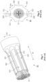
- FIGs 1 and 2 show a crimp sleeve 50 crimped onto an electrical conductor 70 in accordance with the prior art, wherein the crimp sleeve 50 has been arranged on the conductor 70 using eight identical sub-tools of an SRC crimping tool.
- each of the sub-tools has a sub-crimp surface global to it, which is formed as a straight portion of a cylinder lateral surface (cf. the two left-hand and the two right-hand sub-tools 10 in Figure 3 ).
- Such a pressing portion 510 forms a comparatively large circumferential portion of the crimp sleeve 50 on the conductor 70 in comparison with a crimping rib 520 (cf. below).
- Sub-tool gaps 12 are necessarily arranged between each two directly adjacent sub-tools 10 in circumferential direction Um of the SRC crimping tool (cf. again Figure 3 ).
- Sub-tool gaps 12 cause axial Ax crimping ribs 520 in the crimp sleeve 50 arranged on the conductor 70 during crimping.
- Such a crimping rib 520 forms a comparatively small circumferential portion of the crimp sleeve 50 on the conductor 70 in comparison with a pressing portion 510.
- a crimp dimension D of the crimp sleeve 50 can be measured.
- the respective crimp dimension D can be measured along a substantially entire axial Ax extent of the pressing portions 510.
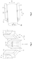
- the curved global sub-crimp surfaces of the sub-tools result in convex measuring locations 531 ( Figure 2 ). These convex formations of the pressing portions 510 are necessary to ensure a good crimp.
- a measurement of the crimp dimension D requires a special measuring device (tip geometry) in order to be able to measure between the crimping ribs 520 of two opposing pressing portions 510, which is illustrated in Figure 2 .
- the comparatively pointed tip geometry of the two measuring fingers 630 in Figure 2 is obviously unsuitable for providing reproducible measurement results due to the convex measuring locations 531. If the tips of the measuring fingers 630 are too small, eccentric measuring positions are possible, which results in incorrect crimp dimensions D, in particular crimp diameter D, at the convex measuring locations 531. According to the invention, however, such tip geometries or standard tip geometries, for example, can be used to measure the crimp dimension D.
- a crimp diameter D is the primary control dimension that must be set correctly.
- the shape of the sub-tools 10 which is common in the prior art results in eight pressing portions 510, which together with eight crimping ribs 520 form the crimp sleeve 50 in circumferential direction Um.
- the distance between opposing pressing portions 510 i.e. a crimp diameter D, should be the same for all four directions over the entire length of the pressing portions 510.
- the crimp diameter D can vary in axial direction Ax and/or in circumferential direction Um of the crimp sleeve 50 depending on a position of a measuring location, i.e. where the measuring fingers 630 (cf. Figures 6 to 8 ) of a measuring device are applied to/on the crimp sleeve 50.
- the measurement must also exclude the crimping ribs 520 between the P pressing portions 510, which requires a measuring tip geometry geometrically linked to the size of the crimp sleeve 50 in order to reduce inconsistencies in the measurements.
- At least one measuring location 530 is provided in the crimp sleeve 50 according to the invention by means of a crimping tool 1 according to the invention in a crimping method according to the invention, wherein a crimp dimension D, in particular a crimp diameter D, of the crimp sleeve 50 can be measured in accordance with the invention by means of the measuring location 530 according to the invention.
- the crimp sleeve 50 is preferably that of a crimp terminal, e.g. a crimp terminal of an assembled cable.
- measuring locations 530 are arranged in pairs on/in the crimp sleeve 50.
- measuring locations 530 relating to one another have the same axial Ax position in/on the crimp sleeve 50.
- a measuring finger 630 of a measuring device can then be placed on the outside of the crimp sleeve 50 at a single measuring location 530 and the crimp dimension D can be measured.
- another crimping tool for example comprising a crimping anvil and at least one crimping punch, can of course be used.
- the crimping tool 1 or SRC crimping tool 1 according to the invention is constructed globally as described above for this purpose.
- at least one sub-tool 10 has a local measuring location insertion device 130 arranged as a negative in and/or as a positive on the global sub-crimp surface 110.
- two sub-tools 10 lying opposite one another in radial direction Ra or a plurality of such sub-tools 10 lying opposite one another in pairs have such local measuring location insertion devices 130 in/on their global sub-crimp surfaces 110.
- Such a measuring location insertion device 130 can be configured as described above.
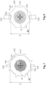
- the measuring location insertion device 130 is arranged in particular as a groove 130 preferably substantially in an axial Ax centre in the relevant sub-tool 10 (cf. Figures 3 and 4 ).
- the groove 130 extending into the global sub-crimp surface 110 of the relevant sub-tool 10 has a straight or tangential (with respect to a curvature of a sub-crimp surface 110) groove base.
- other negatives are also possible as measuring location insertion devices 130, such as, for example: an indentation, a bead, etc.
- a negative is, for example, a lack of material in the global sub-crimp surface 110 or a recess-like deviation from a regular surface of the global sub-crimp surface 110.
- the measuring location insertion device 130 is arranged in particular as a convex protrusion 130 preferably substantially in an axial Ax centre in the relevant sub-tool 10 (not shown in the figures).
- the convex protrusion 130 is formed on the global sub-crimp surface 110 of the relevant sub-tool 10 as a portion of an ellipsoid or a solid sphere.
- measuring location insertion devices 130 such as, for example: a protrusion, a beam shape, etc.
- a positive is, for example, an additional material at/on the global sub-crimp surface 110 or a protrusion-like deviation from a regular surface of the global sub-crimp surface 110.
- the crimp sleeve 50 for example of the terminal, has at least one local measuring location 530 for determining a crimp dimension D, in particular a crimp diameter D, of the crimp sleeve 50 at/in at least one of its pressing portions 510.
- the crimp sleeve 50 has two measuring locations 530 diametrically opposite one another in radial direction Ra or a plurality of such pairs of diametrically opposite measuring locations at/in its pressing portions 510.
- Such a measuring location 530 can be configured as described above.
- the crimp sleeve 50 has, analogously to a negative as the measuring location insertion device 130 of the crimping tool 1, a preferably axially centred positive as the measuring location 530 (cf. Figures 5 to 7 ), or, analogously to a positive as the measuring location insertion device 130 of the crimping tool 1, a preferably axially centred negative as the measuring location 530 (cf. Figure 8 ).
- a negative or such a positive can be of any shape, as long as measuring surfaces of the measuring locations 530 can be realized, on which measuring fingers 630 can be placed.
- this can be configured, for example, as a web 530 which extends in circumferential direction Um of the crimp sleeve 50.
- the web 530 has a straight or tangential extent (with respect to a circumferential Um curvature of a pressing portion 510 or crimp sleeve 50).
- the web 530 can be arranged here between two directly adjacent crimping ribs 520.
- a measuring surface of the web 530 can completely bridge two directly adjacent crimping ribs 520 ( Figures 5 and 6 ), and, in a second case, a measuring surface of the web 530 can be arranged between two directly adjacent crimping ribs 520 ( Figure 7 ).
- a single negative measuring location 530 this can be formed, for example, as a substantially convex measuring location 530 in a pressing portion 510 of the crimp sleeve 50 ( Figure 8 ).
- the positive or negative measuring location 530 can have a substantially planar or convex measuring surface, which is arranged on the outside of the crimp sleeve 50.
- a single measuring surface is arranged between two directly adjacent crimping ribs 520 or bridges them. If necessary, a concave measuring surface of a measuring location 530 can of course also be arranged.
- a local measuring location 530 is formed into the resulting pressing portion 510 of the crimping crimp sleeve 50 during crimping of the crimp sleeve 50.
- the measuring location 530 is formed into the pressing portion 510 by plastic forming of a material of the crimp sleeve 50.
- at least one pair of measuring locations 530/530 is formed into the relevant pressing portions 510, wherein the measuring locations 530, 530 of the pair of measuring locations 530/530 are diametrically opposite one another with respect to the radial direction Ra of the crimp sleeve 50.
- a single measuring location 530 is arranged between two directly adjacent crimping ribs 520 in the crimping process.
- the measuring location 530 can divide the pressing portion 510 into which it has been formed into two axial (Ax) portions, which can preferably be approximately the same length.
- the crimp dimension D in particular the crimp diameter D, can be measured after the crimping process.
- the measuring process can take place shortly after the crimping process or also later, for example at a different location.
- a measuring finger 630 is no longer positioned on a pressing portion 510 (cf. Figure 1 ), but is placed on a local measuring location 530 in the pressing portion 510.
- the measuring location 530 can be configured as a planar or convex measuring surface. If necessary, a convex measuring surface can also be provided.
Landscapes
- Engineering & Computer Science (AREA)
- Manufacturing & Machinery (AREA)
- Manufacturing Of Electrical Connectors (AREA)
- Connections Effected By Soldering, Adhesion, Or Permanent Deformation (AREA)
Applications Claiming Priority (1)
| Application Number | Priority Date | Filing Date | Title |
|---|---|---|---|
| DE102023118936.0A DE102023118936A1 (de) | 2023-07-18 | 2023-07-18 | Crimpwerkzeug und Verfahren zum Crimpen einer Crimphülse |
Publications (2)
| Publication Number | Publication Date |
|---|---|
| EP4496128A2 true EP4496128A2 (fr) | 2025-01-22 |
| EP4496128A3 EP4496128A3 (fr) | 2025-03-19 |
Family
ID=91958149
Family Applications (1)
| Application Number | Title | Priority Date | Filing Date |
|---|---|---|---|
| EP24189197.7A Pending EP4496128A3 (fr) | 2023-07-18 | 2024-07-17 | Outil de sertissage et procédé de sertissage d'un manchon de sertissage |
Country Status (5)
| Country | Link |
|---|---|
| US (1) | US20250030212A1 (fr) |
| EP (1) | EP4496128A3 (fr) |
| JP (1) | JP7769050B2 (fr) |
| CN (1) | CN119340761A (fr) |
| DE (1) | DE102023118936A1 (fr) |
Family Cites Families (7)
| Publication number | Priority date | Publication date | Assignee | Title |
|---|---|---|---|---|
| US4890384A (en) * | 1988-08-25 | 1990-01-02 | Amp Incorporated | Method of crimping an electrical connection |
| FR2865579A1 (fr) * | 2004-01-27 | 2005-07-29 | Framatome Connectors Int | Contact electrique serti a fut ferme, procede de sertissage d'un tel contact, et outil de sertissage correspondant. |
| GB2453360A (en) * | 2007-10-04 | 2009-04-08 | Deutsch Uk | A wire crimp,a crimping tool and a crimping method |
| JP5959450B2 (ja) | 2013-02-22 | 2016-08-02 | 古河電気工業株式会社 | ワイヤハーネスおよび端子 |
| JP2014164930A (ja) | 2013-02-23 | 2014-09-08 | Furukawa Electric Co Ltd:The | 電線付き端子及びその製造方法 |
| JP5718429B2 (ja) * | 2013-10-23 | 2015-05-13 | 株式会社フジクラ | 端子接続装置及び端子付き電線の製造方法 |
| DE102019101016A1 (de) | 2019-01-16 | 2020-07-16 | Harting Electric Gmbh & Co. Kg | Verfahren und Vorrichtung zur Überprüfung der Qualität einer Crimpung |
-
2023
- 2023-07-18 DE DE102023118936.0A patent/DE102023118936A1/de active Pending
-
2024
- 2024-07-11 US US18/769,491 patent/US20250030212A1/en active Pending
- 2024-07-12 JP JP2024112083A patent/JP7769050B2/ja active Active
- 2024-07-16 CN CN202410950966.5A patent/CN119340761A/zh active Pending
- 2024-07-17 EP EP24189197.7A patent/EP4496128A3/fr active Pending
Also Published As
| Publication number | Publication date |
|---|---|
| EP4496128A3 (fr) | 2025-03-19 |
| JP7769050B2 (ja) | 2025-11-12 |
| US20250030212A1 (en) | 2025-01-23 |
| DE102023118936A1 (de) | 2025-01-23 |
| CN119340761A (zh) | 2025-01-21 |
| JP2025015462A (ja) | 2025-01-30 |
Similar Documents
| Publication | Publication Date | Title |
|---|---|---|
| JP4209775B2 (ja) | 改良された径方向弾性的電気コネクタおよびその製造方法 | |
| KR102094628B1 (ko) | 전기 플러그 커넥터용 접촉 슬리브 | |
| JP4988927B2 (ja) | スプリング接点アセンブリ | |
| JP2018537826A (ja) | プラグコネクタソケット | |
| US7575465B2 (en) | Wire and cable insulation markings for connector termination | |
| US9431721B2 (en) | Contact element | |
| JPS63102182A (ja) | 凸面状の係合片を有する電気的なソケットコンタクト | |
| US11664617B2 (en) | Electrical terminal, method for manufacturing elastic terminal, electrical connector and electronic device | |
| CN102511111B (zh) | 压接端子 | |
| JPH06325811A (ja) | ソケット型ターミナル | |
| EP2159880A1 (fr) | Contact et fil connecté à un contact | |
| JP2005535099A (ja) | 接触子の製造方法 | |
| US11670897B2 (en) | Plug connectors for a plug connector system, plug connector system and method for producing a plug connector system | |
| JPH0623173U (ja) | 電気コネクタ用ソケットコンタクト | |
| US3098517A (en) | Connector crimping die set | |
| WO2019235207A1 (fr) | Support de ci | |
| EP4496128A2 (fr) | Outil de sertissage et procédé de sertissage d'un manchon de sertissage | |
| EP1742300A1 (fr) | Organe de contact et procédé de fabrication associé | |
| US11431113B2 (en) | Crimp connection and crimp method for a crimp assembly with at least one retention shoulder | |
| JPS6138587B2 (fr) | ||
| EP3032653B1 (fr) | Structure de connexion pour fil électrique en aluminium | |
| EP1739791A1 (fr) | Contact pour connexion par sertissage et capteur de gaz | |
| CN103503237B (zh) | 连接器 | |
| JP6987006B2 (ja) | 電子制御装置のコネクタ端子形状 | |
| KR101729068B1 (ko) | 커넥터 지그 |
Legal Events
| Date | Code | Title | Description |
|---|---|---|---|
| PUAI | Public reference made under article 153(3) epc to a published international application that has entered the european phase |
Free format text: ORIGINAL CODE: 0009012 |
|
| STAA | Information on the status of an ep patent application or granted ep patent |
Free format text: STATUS: THE APPLICATION HAS BEEN PUBLISHED |
|
| AK | Designated contracting states |
Kind code of ref document: A2 Designated state(s): AL AT BE BG CH CY CZ DE DK EE ES FI FR GB GR HR HU IE IS IT LI LT LU LV MC ME MK MT NL NO PL PT RO RS SE SI SK SM TR |
|
| PUAL | Search report despatched |
Free format text: ORIGINAL CODE: 0009013 |
|
| AK | Designated contracting states |
Kind code of ref document: A3 Designated state(s): AL AT BE BG CH CY CZ DE DK EE ES FI FR GB GR HR HU IE IS IT LI LT LU LV MC ME MK MT NL NO PL PT RO RS SE SI SK SM TR |
|
| RIC1 | Information provided on ipc code assigned before grant |
Ipc: H01R 43/058 20060101ALI20250210BHEP Ipc: H01R 43/048 20060101ALI20250210BHEP Ipc: H01R 4/20 20060101AFI20250210BHEP |
|
| STAA | Information on the status of an ep patent application or granted ep patent |
Free format text: STATUS: REQUEST FOR EXAMINATION WAS MADE |
|
| 17P | Request for examination filed |
Effective date: 20250912 |