EP4501613A1 - Installation pour la fabrication de composants d'un pneu de véhicule - Google Patents
Installation pour la fabrication de composants d'un pneu de véhicule Download PDFInfo
- Publication number
- EP4501613A1 EP4501613A1 EP24191340.9A EP24191340A EP4501613A1 EP 4501613 A1 EP4501613 A1 EP 4501613A1 EP 24191340 A EP24191340 A EP 24191340A EP 4501613 A1 EP4501613 A1 EP 4501613A1
- Authority
- EP
- European Patent Office
- Prior art keywords
- parking position
- front machine
- carcass
- parking
- machine
- Prior art date
- Legal status (The legal status is an assumption and is not a legal conclusion. Google has not performed a legal analysis and makes no representation as to the accuracy of the status listed.)
- Pending
Links
Images

Classifications
-
- B—PERFORMING OPERATIONS; TRANSPORTING
- B29—WORKING OF PLASTICS; WORKING OF SUBSTANCES IN A PLASTIC STATE IN GENERAL
- B29D—PRODUCING PARTICULAR ARTICLES FROM PLASTICS OR FROM SUBSTANCES IN A PLASTIC STATE
- B29D30/00—Producing pneumatic or solid tyres or parts thereof
- B29D30/005—General arrangement or lay-out of plants for the processing of tyres or parts thereof
- B29D2030/0055—Optimization of the cycle times of the tyre manufacturing process, e.g. adaptation of the tyre building process to the vulcanization process
-
- B—PERFORMING OPERATIONS; TRANSPORTING
- B29—WORKING OF PLASTICS; WORKING OF SUBSTANCES IN A PLASTIC STATE IN GENERAL
- B29D—PRODUCING PARTICULAR ARTICLES FROM PLASTICS OR FROM SUBSTANCES IN A PLASTIC STATE
- B29D30/00—Producing pneumatic or solid tyres or parts thereof
- B29D30/06—Pneumatic tyres or parts thereof (e.g. produced by casting, moulding, compression moulding, injection moulding, centrifugal casting)
- B29D30/08—Building tyres
- B29D30/20—Building tyres by the flat-tyre method, i.e. building on cylindrical drums
- B29D2030/202—Building tyres by the flat-tyre method, i.e. building on cylindrical drums the building drums being movable, i.e. not permanently connected to a fixed frame
Definitions
- the present invention relates to a plant for producing components of a pneumatic vehicle tire, in particular a carcass station which has a stationary carcass servicer and at least one front machine for producing a tire carcass of a pneumatic vehicle tire.
- carcass drum In a carcass station, different tire components are wound onto a carcass drum in a carcass station and further processed.
- carcass drum for example, comprises radially expandable segments that can be covered by a rubber sleeve in the form of a tube.
- EP 2 789 458 A1 a system and a method for producing a carcass for a pneumatic vehicle tire, which is completed with a belt assembly and a tread as well as other optional components to form the finished green tire, wherein the system has several work stations, in particular a carcass station, a belt-tread station and a cambering station.
- a carcass station 10 of this type is in the Fig. 1
- the carcass station 10 includes a carcass servicer 12 and a front machine 14.
- the front machine 14 has a left machine box 16, a right machine box 18 and a carcass building drum 20. After a tire carcass has been produced in the carcass station 10, this tire carcass can either be moved using a transfer device or alternatively manually transferred for transfer to a Fig. 1 not shown crowning station.
- the reference number 22 designates the left machine box in the open position.
- the front machine 14 is set up for a specific tire type with a specified size, an individual drum and additional dimension-dependent equipment. If the carcass station 10 is to produce a different tire type, the front machine 14 must be converted. For example, the carcass building drum 20 and/or dimension-relevant parts for the new tire type must be changed. During this conversion time, the carcass station 10 cannot produce. This leads to a machine downtime due to tool changes.
- a system for producing components of a pneumatic vehicle tire has a work station with a first front machine.
- the system can be configured such that the first front machine is positioned in a working position.
- the system also includes a first parking position and a second parking position.
- the system can be configured such that a second front machine is positioned in the first parking position and the second parking position is not occupied, wherein the first front machine can be moved between the working position and the second parking position and the second front machine can be moved between the first parking position and the working position.
- the second front machine is movable from the first parking position to the working position when the first front machine is in the second parking position, and the first front machine is movable from the second parking position to the working position when the second front machine is in the first parking position.
- the first parking position and the second parking position are each adjacent to the working position.
- the working position and the first and second parking positions are arranged along a first transfer axis, and the first front machine and the second front machine are movable along the first transfer axis.
- the system has a third parking position and the system is configurable such that the third parking position is not occupied, wherein the first front machine is movable from the working position via the third parking position to the second parking position when the second front machine is parked in the first parking position, and wherein the second front machine is movable from the first parking position via the third parking position to the working position when the first front machine is moved from the working position to the second parking position.
- the working position and the third parking position are arranged along a first transfer axis, and the first parking position and the second parking position are each adjacent to the third parking position.
- the first, second and third parking positions are arranged along a second transfer axis which is at an angle not equal to Zero to the first transfer axis, in particular perpendicular to the first transfer axis.
- the working position and the first parking position are arranged along a first transfer axis
- the second parking position is arranged along a second transfer axis which is arranged at a non-zero angle to the first transfer axis
- the first front machine is movable from the working position to the second parking position when the second front machine is in the first parking position
- the second front machine is movable from the first parking position to the working position when the first front machine is in the second parking position
- the second transfer axis is arranged perpendicular to the first transfer axis.
- the plant is a carcass station which can be used for producing a carcass of the pneumatic vehicle tire.
- the carcass station comprises a stationary carcass servicer.
- each front machine has a carcass machine with a carcass building drum.
- the system has a horizontal transfer system, a vertical transfer system or a combination of a horizontal and vertical transfer system with which the two front machines can be moved.
- Fig. 2 shows a system for producing components of a pneumatic vehicle tire, which has a work station with a front machine 54.
- the work station is in particular a carcass station 50, which has a stationary carcass servicer 52 and the front machine 54 for producing a tire carcass of the pneumatic vehicle tire.
- the carcass station 50 also includes a second front machine 56, which is positioned on a first parking position 58, and a second parking position 60, which is not occupied.
- the first front machine 54 has a left machine box 62, a right machine box 64 and a carcass building drum 66, with which in particular first components of the carcass can be produced.
- a transfer device or by means of a manual transfer, the carcass is transported after its production in the first front machine 54 to a Fig. 2
- the next station not shown, is the crowning station.
- Reference number 68 designates the left machine box in the open position.
- the carcass station 50 with the carcass servicer 52 and the front machines 54 and 56 can be designed in a manner known per se.
- the second front machine 56 is preferably identical or of the same construction as the first front machine 54.
- the second front machine 56 also has a left machine box 62', a right machine box 64' and a carcass building drum 66'.
- the reference number 68' again designates the left machine box in the open position.
- the first front machine 54 can be used with the existing Equipment can no longer be used for this purpose as it is specifically designed for the carcass of the first tire type.
- the first front machine 54 which is positioned at a working position 70, is therefore moved from the working position 70 to the second parking position 60, as indicated by a double arrow P1.
- the second front machine 56 is then moved from the first parking position 58 to the working position 70, indicated by a double arrow P2.
- the second front machine 56 is already prepared for the second tire type, so that the carcass station 50 is ready for production after the second front machine 56 has moved to the working position 70. This situation is shown in the Fig. 3 The time during which the carcass station 50 is not ready for production can therefore be kept very short.
- the first front machine 54 which is now located in the second parking position 60, can be converted for a carcass of a further, third tire type during the time in which the second front machine 56 is producing carcasses for the second tire type, for example by changing the carcass building drum 66 and/or dimensionally relevant parts for the third tire type.
- the second front machine 56 can be moved back to the first parking position 58 when the production of the second tire type in the second front machine 56 has ended, and the first front machine 54 can then be moved back to the working position 70 so that carcasses of the third tire type can subsequently be produced by the carcass station 50.
- One of the two front machines 54 and 56 can therefore be converted at a time while the carcass station 50 is in operation, which can therefore remain in continuous operation.
- the second front machine 56 can be moved arbitrarily between the first parking position 58 and the working position 70 when the first front machine 54 is located at the second parking position 60, and the first front machine 54 can be moved arbitrarily between the working position 70 and the second parking position 60 when the second front machine 56 is located at the first parking position 58, along an axis z, a transfer axis or a transfer path, as shown in the Fig. 2 and 3 indicated by the double arrows P1 and P2.
- the first parking position 58 and the second parking position 60 are each adjacent to the working position 70.
- the working position 70 is located directly in front of the carcass machine 64, in contrast to the parking positions 58 and 60, which are further away from the carcass machine 64.
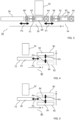
- a second embodiment of the plant for producing components of a pneumatic vehicle tire is shown in the Fig. 4 and 5 shown schematically.
- the system includes in particular a carcass station 86, which has the stationary carcass servicer 52 and the first front machine 54.
- the first front machine 54 is positioned at the working position 70 and is equipped here, for example, for producing a carcass of a fourth tire type of a pneumatic vehicle tire.
- the carcass station 86 also includes the second front machine 56, which is positioned at a first parking position 80, as well as a second parking position 82 and a third parking position 84, both of which are unoccupied.
- the third parking position 84 is arranged in a row with the working position 70, along an axis z', and the first parking position 80 is arranged parallel to the third parking position 84, in the positive direction of an axis y.
- the second parking position 82 is also arranged parallel to the third parking position 84, but in the negative direction of the axis y, so that the first Parking position 80 and the second parking position 82 are each directly adjacent to the third parking position 84.
- the third parking position 84 is directly adjacent to the working position 70.
- the y axis and the z' axis are preferably two rectangular coordinates, and in particular transfer axes along which the first front machine 52 and the second front machine 54 can be moved.
- the first front machine 54 can be moved from the working position 70 to the third parking position 84 and then moved either to the first parking position 80 or to the second parking position 82, depending on where the second front machine 56 is positioned: on the first parking position 80 or on the second parking position 82.
- the front machine 54 can no longer be used for this purpose with the existing equipment, since it is specially designed for the carcass of the fourth tire type.
- the first front machine 54 which is positioned at the working position 70, is therefore moved from the working position 70 to the third parking position 84, as indicated by a double arrow P3 in the Fig. 4 and then to the second parking position 82, indicated by a double arrow P4. Subsequently, the second front machine 56 is moved from the first parking position 80 to the third parking position 84, indicated by a double arrow P5, and then to the working position 70, indicated by the double arrow P3 and in the Fig. 5 shown.
- the second front machine 56 is already prepared for the fifth tire type, so that the carcass station 86 is ready for production after the second front machine 56 has moved to the working position 70, Fig. 5 .
- the time in which the carcass station 86 is not ready for production, can therefore also be kept very short in this embodiment.
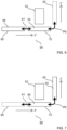
- a third embodiment of the plant for producing components of a pneumatic vehicle tire is shown in the Fig. 6 and 7 shown schematically.
- the system includes in particular a carcass station 94, which has the stationary carcass servicer 52 and the first front machine 54.
- the first front machine 54 is positioned at the working position 70 and is equipped here, for example, for producing a carcass of a sixth tire type of a pneumatic vehicle tire.
- the carcass station 94 also includes the second front machine 56, which is positioned at a first parking position 90, and a second parking position 92, which is not occupied.
- the first parking position 90 is arranged in a row with the working position 70, along an axis z", and the second parking position 92 is arranged at an angle to the first parking position 90, in the direction of an axis y'.
- the first parking position 90 as well as the second parking position 92 are each adjacent to the working position 70.
- the axis y' and the axis z" in this embodiment are preferably two rectangular coordinates, and in particular transfer axes along which the first front machine 54 and the second front machine 56 can be moved.
- the first front machine 54 can thereby be moved from the working position 70 to the second parking position 92, as shown in the Fig. 6 indicated by a double arrow P6, and then the second front machine 56 can be moved from the first parking position 90 to the working position 70, as shown in the Fig. 7 indicated by a double arrow P7.
- the second front machine 56 is already prepared for a seventh tire type with a different size, so that the carcass station 94 is ready for production after the second front machine 56 has moved to the working position 70.
- the time during which the carcass station 94 is not ready for production can therefore also be kept very short in this embodiment.
- the two front machines 54 and 56 are not stationary but are arranged to be movable and can be moved between the working position and the parking positions, for example using a horizontal or vertical transfer system of the system, or using a combination of a horizontal or vertical transfer system.
- the term "movable” is therefore not limited to horizontal movements, but can also include vertical and other movements.
Landscapes
- Engineering & Computer Science (AREA)
- Mechanical Engineering (AREA)
- Tyre Moulding (AREA)
Applications Claiming Priority (1)
| Application Number | Priority Date | Filing Date | Title |
|---|---|---|---|
| DE102023207364.1A DE102023207364A1 (de) | 2023-08-01 | 2023-08-01 | Anlage zur Herstellung von Komponenten eines Fahrzeugluftreifens |
Publications (1)
| Publication Number | Publication Date |
|---|---|
| EP4501613A1 true EP4501613A1 (fr) | 2025-02-05 |
Family
ID=92108631
Family Applications (1)
| Application Number | Title | Priority Date | Filing Date |
|---|---|---|---|
| EP24191340.9A Pending EP4501613A1 (fr) | 2023-08-01 | 2024-07-29 | Installation pour la fabrication de composants d'un pneu de véhicule |
Country Status (2)
| Country | Link |
|---|---|
| EP (1) | EP4501613A1 (fr) |
| DE (1) | DE102023207364A1 (fr) |
Citations (4)
| Publication number | Priority date | Publication date | Assignee | Title |
|---|---|---|---|---|
| EP2789458A1 (fr) | 2013-04-11 | 2014-10-15 | Continental Reifen Deutschland GmbH | Procédé et installation de fabrication d'une carcasse de pneu de véhicule |
| EP2516141B1 (fr) * | 2009-12-21 | 2016-04-13 | Pirelli Tyre S.p.A. | Procédé et installation de production de pneumatiques. |
| DE102015203023A1 (de) * | 2015-02-19 | 2016-08-25 | Continental Reifen Deutschland Gmbh | Verfahren zur Herstellung eines Fahrzeugreifens |
| EP3732031B1 (fr) * | 2017-12-28 | 2022-03-30 | Pirelli Tyre S.p.A. | Processus et installation pour la production de pneus pour des roues de véhicule |
-
2023
- 2023-08-01 DE DE102023207364.1A patent/DE102023207364A1/de active Pending
-
2024
- 2024-07-29 EP EP24191340.9A patent/EP4501613A1/fr active Pending
Patent Citations (4)
| Publication number | Priority date | Publication date | Assignee | Title |
|---|---|---|---|---|
| EP2516141B1 (fr) * | 2009-12-21 | 2016-04-13 | Pirelli Tyre S.p.A. | Procédé et installation de production de pneumatiques. |
| EP2789458A1 (fr) | 2013-04-11 | 2014-10-15 | Continental Reifen Deutschland GmbH | Procédé et installation de fabrication d'une carcasse de pneu de véhicule |
| DE102015203023A1 (de) * | 2015-02-19 | 2016-08-25 | Continental Reifen Deutschland Gmbh | Verfahren zur Herstellung eines Fahrzeugreifens |
| EP3732031B1 (fr) * | 2017-12-28 | 2022-03-30 | Pirelli Tyre S.p.A. | Processus et installation pour la production de pneus pour des roues de véhicule |
Also Published As
| Publication number | Publication date |
|---|---|
| DE102023207364A1 (de) | 2025-02-06 |
Similar Documents
| Publication | Publication Date | Title |
|---|---|---|
| DE69314067T2 (de) | Anlage zur Herstellung von Reifenkarkassen für Fahrzeugräder | |
| DE102009025759A1 (de) | Verfahren und Vorrichtung zum Aufbauen eines PKW-Radialreifens | |
| DE69413453T2 (de) | Vorrichtung und Verfahren zur Herstellung eines radialen Rohreifens und Übertragungseinheit geeignet zum Gebrauch in einer derartigen Vorrichtung | |
| WO2010052103A1 (fr) | Dispositif de montage d'une carcasse de bandage de roue de véhicule | |
| WO2006003054A1 (fr) | Procede et dispositif pour realiser un pneumatique radial | |
| EP1765581B1 (fr) | Procede et dispositif pour positionner des tringles de talon | |
| DE69515280T2 (de) | Vorrichtung zum einstufigen Aufbauen von Luftreifen | |
| DE19918523C1 (de) | Reifenaufbauvorrichtung | |
| EP4501613A1 (fr) | Installation pour la fabrication de composants d'un pneu de véhicule | |
| DE102023207362A1 (de) | Anlage zur Herstellung von Komponenten eines Fahrzeugluftreifens | |
| EP2789458B1 (fr) | Procédé et installation de fabrication d'une carcasse de pneu de véhicule | |
| EP4112287B1 (fr) | Machine de fabrication de pneus et procédé d'utilisation d'une machine de fabrication de pneus | |
| DE69012964T2 (de) | Reifenaufbautrommel. | |
| DE60211956T2 (de) | Verfahren und vorrichtung für den reifenaufbau | |
| DE3247441A1 (de) | Verfahren und vorrichtung zum herstellen von wulstkernen fuer luftreifen | |
| DE102013103633A1 (de) | Verfahren und Anlage zur Herstellung einer Karkasse für einen Fahrzeugluftreifen | |
| EP4015206A2 (fr) | Procédé et dispositif de fabrication d'au moins deux profilés pour un pneu de véhicule | |
| DE102009025758A1 (de) | Verfahren zum Aufbauen eines Fahrzeugreifens für einen Personenkraftwagen mit einer Reifenaufbaumaschine | |
| DE102015203023A1 (de) | Verfahren zur Herstellung eines Fahrzeugreifens | |
| EP3999327B1 (fr) | Procédé et dispositif de fabrication de pneus crus | |
| EP3206864A1 (fr) | Dispositif et procédé de production de pneus crus | |
| EP1954481A1 (fr) | Procede de fabrication d'un ensemble de ceinture pour bandages pneumatiques de vehicule | |
| WO2005090061A1 (fr) | Dispositif pour fabriquer des elements de pneumatiques et procede d'exploitation correspondant | |
| DE2516419A1 (de) | Vorrichtung zum herstellen einer gefalteten einlage fuer fahrzeugluftreifen | |
| DE4243350A1 (en) | System to apply beads in tyre prodn. - has cylinder which moves bead application ring obliquely up and down and is mounted on structure which slides along horizontal track |
Legal Events
| Date | Code | Title | Description |
|---|---|---|---|
| PUAI | Public reference made under article 153(3) epc to a published international application that has entered the european phase |
Free format text: ORIGINAL CODE: 0009012 |
|
| STAA | Information on the status of an ep patent application or granted ep patent |
Free format text: STATUS: THE APPLICATION HAS BEEN PUBLISHED |
|
| AK | Designated contracting states |
Kind code of ref document: A1 Designated state(s): AL AT BE BG CH CY CZ DE DK EE ES FI FR GB GR HR HU IE IS IT LI LT LU LV MC ME MK MT NL NO PL PT RO RS SE SI SK SM TR |
|
| STAA | Information on the status of an ep patent application or granted ep patent |
Free format text: STATUS: REQUEST FOR EXAMINATION WAS MADE |
|
| 17P | Request for examination filed |
Effective date: 20250805 |