EP4516452A1 - Procédé de polissage d'une surface - Google Patents
Procédé de polissage d'une surface Download PDFInfo
- Publication number
- EP4516452A1 EP4516452A1 EP24197168.8A EP24197168A EP4516452A1 EP 4516452 A1 EP4516452 A1 EP 4516452A1 EP 24197168 A EP24197168 A EP 24197168A EP 4516452 A1 EP4516452 A1 EP 4516452A1
- Authority
- EP
- European Patent Office
- Prior art keywords
- zone
- unpolished
- protective cover
- lens
- polishing
- Prior art date
- Legal status (The legal status is an assumption and is not a legal conclusion. Google has not performed a legal analysis and makes no representation as to the accuracy of the status listed.)
- Pending
Links
Images

Classifications
-
- B—PERFORMING OPERATIONS; TRANSPORTING
- B29—WORKING OF PLASTICS; WORKING OF SUBSTANCES IN A PLASTIC STATE IN GENERAL
- B29D—PRODUCING PARTICULAR ARTICLES FROM PLASTICS OR FROM SUBSTANCES IN A PLASTIC STATE
- B29D11/00—Producing optical elements, e.g. lenses or prisms
- B29D11/00009—Production of simple or compound lenses
- B29D11/00432—Auxiliary operations, e.g. machines for filling the moulds
-
- B—PERFORMING OPERATIONS; TRANSPORTING
- B24—GRINDING; POLISHING
- B24B—MACHINES, DEVICES, OR PROCESSES FOR GRINDING OR POLISHING; DRESSING OR CONDITIONING OF ABRADING SURFACES; FEEDING OF GRINDING, POLISHING, OR LAPPING AGENTS
- B24B1/00—Processes of grinding or polishing; Use of auxiliary equipment in connection with such processes
-
- B—PERFORMING OPERATIONS; TRANSPORTING
- B24—GRINDING; POLISHING
- B24B—MACHINES, DEVICES, OR PROCESSES FOR GRINDING OR POLISHING; DRESSING OR CONDITIONING OF ABRADING SURFACES; FEEDING OF GRINDING, POLISHING, OR LAPPING AGENTS
- B24B13/00—Machines or devices designed for grinding or polishing optical surfaces on lenses or surfaces of similar shape on other work; Accessories therefor
- B24B13/01—Specific tools, e.g. bowl-like; Production, dressing or fastening of these tools
- B24B13/012—Specific tools, e.g. bowl-like; Production, dressing or fastening of these tools conformable in shape to the optical surface, e.g. by fluid pressure acting on an elastic membrane
-
- B—PERFORMING OPERATIONS; TRANSPORTING
- B24—GRINDING; POLISHING
- B24B—MACHINES, DEVICES, OR PROCESSES FOR GRINDING OR POLISHING; DRESSING OR CONDITIONING OF ABRADING SURFACES; FEEDING OF GRINDING, POLISHING, OR LAPPING AGENTS
- B24B19/00—Single-purpose machines or devices for particular grinding operations not covered by any other main group
- B24B19/20—Single-purpose machines or devices for particular grinding operations not covered by any other main group for grinding dies
-
- B—PERFORMING OPERATIONS; TRANSPORTING
- B29—WORKING OF PLASTICS; WORKING OF SUBSTANCES IN A PLASTIC STATE IN GENERAL
- B29D—PRODUCING PARTICULAR ARTICLES FROM PLASTICS OR FROM SUBSTANCES IN A PLASTIC STATE
- B29D11/00—Producing optical elements, e.g. lenses or prisms
- B29D11/00009—Production of simple or compound lenses
- B29D11/00317—Production of lenses with markings or patterns
- B29D11/00326—Production of lenses with markings or patterns having particular surface properties, e.g. a micropattern
-
- B—PERFORMING OPERATIONS; TRANSPORTING
- B29—WORKING OF PLASTICS; WORKING OF SUBSTANCES IN A PLASTIC STATE IN GENERAL
- B29D—PRODUCING PARTICULAR ARTICLES FROM PLASTICS OR FROM SUBSTANCES IN A PLASTIC STATE
- B29D11/00—Producing optical elements, e.g. lenses or prisms
- B29D11/00932—Combined cutting and grinding thereof
-
- B—PERFORMING OPERATIONS; TRANSPORTING
- B29—WORKING OF PLASTICS; WORKING OF SUBSTANCES IN A PLASTIC STATE IN GENERAL
- B29L—INDEXING SCHEME ASSOCIATED WITH SUBCLASS B29C, RELATING TO PARTICULAR ARTICLES
- B29L2011/00—Optical elements, e.g. lenses, prisms
- B29L2011/0016—Lenses
Definitions
- the present invention is in the ophthalmic field, and it relates to a method for manufacturing an ophthalmic device comprising a polishing step of a surface of a mold or an ophthalmic lens or a semi-finished lens.
- the present invention is also related to an intermediate mold intended to be used for molding the ophthalmic lens.
- the present invention is also related to a finished ophthalmic lens or a semi-finished ophthalmic lens.
- a spectacle lens is specifically manufactured according to every wearer's needs which may take the form of specifications defined in a prescription established by an ophthalmologist or an optometrist.
- a lens blank is submitted to various steps to form the desired lens, in particular one, surfacing step, also called cutting step, during which the shape of the lens blank is processed to produce what can be referred to as a surfaced lens so that the latter exhibits desired optical properties.
- the shape of the surface of the lens or the lens blank may be obtained by directly cutting the surface or may be obtained by molding via a mold previously cut according to the desired optical properties.
- the surface quality obtained must be such that no irregularity occurs which would be transmitted to the resulting product and would conduct to digress from the required desired optical properties. Indeed, the resulting product may be very sensitive to these surface irregularities. There is therefore a need for a method that makes it possible to reduce these surface irregularities.
- the irregularities may have several origins.
- these irregularities may occur on the edge or in the center due to cutting instabilities.
- a way to limit these irregularities is to polish the surface of the lens or the lens blank after the cutting step.
- the polishing step may cause an undesirable sharpness reduction, attenuating the desired optical function.
- one option is to polish the protrusions but reducing the quality.
- Another solution is to keep the cut surface without polishing but having some chromatic effects.
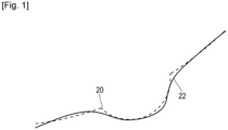
- figure 1 represents a side view of an ophthalmic device manufactured by a method according to the prior art.
- figure 1 represents a protrusion of the ophthalmic device.
- the dot line 20 is the protrusion cut by diamond turning before polishing and the line 22 is the protrusion after polishing.
- the protrusion after polishing doesn't keep the desired shape obtained by cutting before polishing and consequently doesn't have the desired optical function.
- the goal is obtained according to the present disclosure thanks to a method for manufacturing an ophthalmic device, comprising a polishing step to polish a surface of the ophthalmic device comprising at least one unpolished zone.
- the at least one unpolished zone is a zone intended not to be polished.
- the polishing step comprises:
- the ophthalmic device may be a mold or an insert intended to manufacture an ophthalmic lens or semi-finished ophthalmic lens.
- the ophthalmic device may be an ophthalmic lens.
- the ophthalmic lens may be a progressive lens (PAL), or lens for slow down the myopia or Plano lens (without correction).
- PAL progressive lens
- lens for slow down the myopia or Plano lens without correction
- the at least one unpolished zone may be micro elements, protrusion, micro lens, engraving, groove, discontinuity, pattern, figure, scattering element(s), shape.
- the at least one unpolished zone may be at least one cavity or at least one concave micro elements of an ophthalmic lens or a mold to manufacture an ophthalmic lens.
- the protective cover may fill the cavity or the concave micro elements, in other words, the material of the protective cover may fill the cavity or the concave micro elements.
- micro elements may be convex or concave, spherical or aspherical, bifocal or unifocal, or pi-Fresnel.
- the unpolished zone is protrusions
- by covering the at least one unpolished zone is possible to avoid deteriorations of the protrusions and thus to avoid for example chromatics effects.
- Advantageous and convenient features of the manufacturing method are described below.
- the covering may be taping.
- the protective cover may be a protective tape.
- the protective cover may be a film deposed on the surface so as to cover the at least one unpolished zone.
- the protective cover may be at least a layer made by an additive manufacturing process such as Fused Deposition Modeling (FDM), SLS Selective Laser Sintering, Granulate FDM, Multi Jet Fusion (MJF), Material Jetting (MJ).
- FDM Fused Deposition Modeling
- SLS Selective Laser Sintering SLS Selective Laser Sintering
- Granulate FDM Multi Jet Fusion
- MJF Multi Jet Fusion
- MJ Material Jetting
- the covering may be coating by inkjet or spin.
- the covering may be an additive manufacturing process such as Fused Deposition Modeling (FDM), SLS Selective Laser Sintering, Granulate FDM, Multi Jet Fusion (MJF), Material Jetting (MJ).
- FDM Fused Deposition Modeling
- SLS Selective Laser Sintering Granulate FDM
- Multi Jet Fusion MJF
- Material Jetting MJ
- the polishing at least a part of the surface may polish the part of the surface which is no covered by the protective cover.
- the polishing at least a part of the surface may polish the part of the surface which is no covered by the protective cover.
- the polishing may be homogenous on the part of the surface which is no covered by the protective cover.
- the material stock removal by the polishing process may be homogenous on the uncovered surface.
- material of the surface may be removed.
- the thickness of the material removal may be lower than 20 ⁇ m, lower than 1 ⁇ m and preferred lower than 0.1 ⁇ m.
- the surface comprising the at least one unpolished zone may be a surface of a mold intended to be used to mold the ophthalmic lens.
- the surface of the mold before the polishing step may be coated with NiP or ferrous material.
- the surface comprising the at least one unpolished zone may be a surface of a semi-finished lens or a finished lens.
- a surfacing step may be comprised during the manufacturing method.
- the surfacing step uses a tool to surface the surface surface of the ophthalmic device.
- the tool is made of a first material and fixed by a carrier element made of a second material.
- the first material has a higher hardness than the second element.
- the tool may be a diamond tool.
- the thickness of the protective cover may be superior to 10 ⁇ m.
- the thickness of the protective cover may be superior to 20 ⁇ m.
- the thickness of the protective cover may be comprised between 10 ⁇ m and 350 ⁇ m.
- the thickness of the protective cover being superior to 10 ⁇ m, it allows to avoid removing all the protective cover during the polishing step. Indeed, in the field of polishing of ophthalmic element, during the polishing, at least 10 ⁇ m of materials are removed.
- the thickness of the protective cover on the edge may be lower than 200 ⁇ m.
- the thickness of the protective cover on the edge may be lower than 100 ⁇ m.
- the thickness of the protective cover on the edge may be lower than 5 ⁇ m.
- the thickness of the protective cover on the edge may be as thin as possible to warrant the surface continuity between the polished surface and unpolished zone.
- the unpolished zone may be determined by a mask.
- the mask may be had different kind of geometries such as cylinder or semi cylinder or any kind of shape.
- the disclosure also provides, according to a second aspect, an intermediate mold intended to be used to manufacture an ophthalmic lens.
- the intermediate mold may comprise: a metallic bulk, a surface of the metallic bulk comprising the at least one unpolished zone, and a protective cover disposed on a part or on the totality of the at least one unpolished zone.
- the intermediate mold comprising the metallic bulk may comprise a coating having the at least one discontinuity.
- the disclosure also provides, according to a third aspect, an ophthalmic lens.
- the ophthalmic lens comprises: a surface comprising at least one unpolished zone and a protective cover disposed on a part or on the totality of the at least one unpolished zone.
- the disclosure also provides, according to a fourth aspect, a semi-finished ophthalmic lens.
- the semi-finished ophthalmic lens comprises a surface comprising the at least one unpolished zone and a protective cover disposed on a part or on the totality of the at least one unpolished zone.
- Embodiments discussed herein are merely representative and do not limit the scope of the invention. It will also be obvious to one skilled in the art that all the technical features that are defined relative to a process can be transposed, individually or in combination, to a device and conversely, all the technical features relative to a device can be transposed, individually or in combination, to a process.
- the disclosure is directed to a method for manufacturing an ophthalmic device comprising a polishing step to polish a surface of the ophthalmic device comprising at least one unpolished zone, the at least one unpolished zone is a zone intended not to be polished.
- the ophthalmic device may be a lens, an unifocal lens, a bifocal lens, a progressive lens, a semi-finished lens, a mold or an insert intented to manufacture a lens, an unifocal lens, a bifocal lens, a progressive lens, a semi-finished lens.
- the ophthalmic device may be used in the field of single vision, bifocal lens, progressive lens, Plano lens or slowing myopia.
- the at least one unpolished zone may be micro elements, protrusion, micro lens, engraving, groove, discontinuity, pattern, figure, scattering element(s), shape.
- the at least one unpolished zone may be cavity or concave micro elements. It may be at least one cavity or at least one concave micro elements of an ophthalmic lens or a mold to manufacture an ophthalmic lens.
- the protective cover may fill the cavity or the concave micro elements, in other words, the material of the protective cover may fill the cavity or the concave micro elements.
- micro elements may be convex or concave, spherical or aspherical, bifocal or unifocal, or pi-Fresnel.
- the unpolished zone may be esthetical features or technical features to slow done the myopia or technical features to correct visual defects.
- FIG. 2A illustrates the steps of the method of the present disclosure.
- the polishing step comprises:
- the unpolished zone is protrusions
- by covering the at least one unpolished zone is possible to avoid deteriorations of the protrusions and thus to avoid for example chromatics effects.
- Advantageous and convenient features of the manufacturing method are described below.
- the covering may be taping.
- the protective cover may be a protective tape, such as an adhesive film.
- the protective cover may be a film deposed on the surface so as to cover the at least one unpolished zone.
- the protective cover may be at least a layer made by an additive manufacturing process such as Fused Deposition Modeling (FDM), SLS Selective Laser Sintering, Granulate FDM, Multi Jet Fusion (MJF), Material Jetting (MJ).
- FDM Fused Deposition Modeling
- SLS Selective Laser Sintering SLS Selective Laser Sintering
- Granulate FDM Granulate FDM
- MJF Multi Jet Fusion
- MJ Material Jetting
- the covering may be coating by inkjet, spin or by aerosol.
- the covering may be an additive manufacturing process such as Fused Deposition Modeling (FDM), SLS Selective Laser Sintering, Granulate FDM, Multi Jet Fusion (MJF), Material Jetting (MJ).
- FDM Fused Deposition Modeling
- SLS Selective Laser Sintering Granulate FDM
- Multi Jet Fusion MJF
- Material Jetting MJ
- the coating may be a material that changes of state after application, for example from gas or liquid to solid.
- a mask may be used to define the unpolished zone without cover the remainder of the ophthalmic device.
- the protective cover may be Pressure Sensitive Adhesive Tape or polycarbonate or glue or ink or any kind of material which can have the needed features.
- the needed features of the protective cover may be the thickness or the adhesion criterion.
- the thickness of the protective cover on the edge may be lower than 200 ⁇ m.
- the thickness of the protective cover on the edge may be lower than 100 ⁇ m.
- the thickness of the protective cover on the edge may be lower than 5 ⁇ m.
- the thickness of the protective cover on the edge may be as thin as possible to warrant the surface continuity between the polished surface and unpolished zone.
- the adhesion criterion of the protective cover may be determined by considering at least one of the following parameters:
- the thickness of the protective cover may be determined by considering at least one of the following parameters:
- the thickness of the protective cover may be superior to 10 ⁇ m.
- the thickness of the protective cover may be superior to 20 ⁇ m.
- the thickness of the protective cover may be comprised between 10 ⁇ m and 350 ⁇ m.
- the thickness of the protective cover being superior to 10 ⁇ m, it allows to avoid removing all the protective cover during the polishing step. Indeed, in the field of polishing of ophthalmic element, during the polishing, at least 10 ⁇ m of materials are removed.
- the thickness of the protective cover on the edge may be lower than 200 ⁇ m.
- the thickness of the protective cover on the edge may be lower than 100 ⁇ m
- the thickness of the protective cover on the edge may be lower than 5 ⁇ m.
- the thickness of the protective cover on the edge may be as thin as possible to warrant the surface continuity between the polished surface and unpolished zone.
- the polishing at least a part of the surface may polish the part of the surface which is no covered by the protective cover.
- the polishing at least a part of the surface may polish the part of the surface which is no covered by the protective cover.
- the polishing may be homogenous on the part of the surface which is no covered by the protective cover.
- the material stock removal by the polishing process may be homogenous on the uncovered surface.
- the thickness of the material removal may be lower than 20 ⁇ m, lower than 1 ⁇ m and preferred lower than 0.1 ⁇ m.
- the removing may be a chemical (such as solvent or ethanol) or/and mechanical process (such a manual process, ultrasound bath or by rubbing with a cloth )
- the surface comprising the at least one unpolished zone may be a surface of a mold intended to be used to mold the ophthalmic lens.
- the surface of the mold before the polishing step may be coated with NiP or ferrous material.
- the surface comprising the at least one unpolished zone may be a surface of a semi-finished lens or a finished lens.
- the disclosure is directed to a method for manufacturing an ophthalmic device comprising a machining step to obtain the desired surface of the ophthalmic device.
- the machining step may be a cutting step also called a surfacing step.
- the machining step may be a molding step or a replicating step.
- Figure 2B illustrates a method according to an embodiment of the present disclosure taken alone or in combinations, comprising a surfacing step 16.
- a surfacing step 16 may be comprised during the manufacturing method.
- the surfacing step uses a tool to surface the surface of the ophthalmic device.
- the tool is made of a first material and fixed by a carrier element made of a second material.
- the first material has a higher hardness than the second element.
- the tool may be a diamond tool.
- the disclosure also provides, according to a second aspect, an intermediate mold intended to be used to manufacture an ophthalmic lens.
- the intermediate mold may comprise: a metallic bulk, a surface of the metallic bulk comprising the at least one unpolished zone, and a protective cover disposed on a part or on the totality of the at least one unpolished zone.
- the intermediate mold comprising the metallic bulk may comprise a coating having the at least one discontinuity.
- the disclosure also provides, according to a third aspect, an ophthalmic lens.
- the ophthalmic lens comprises: a surface comprising at least one unpolished zone and a protective cover disposed on a part or on the totality of the at least one unpolished zone.
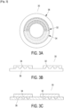
- Figures 3A,3B and 3C represent an ophthalmic device with the protective cover respectively top and side view according two embodiments of the present disclosure.
- the ophthalmic device 30 comprises a base 36.
- the ophthalmic device 30 may comprise further micro elements 32 arranged concentrically on a part of the base.
- the side view of figure 3A is illustrated according to two embodiments on figures 3B and 3C respectively with micro elements convex and concave.
- the base may be plane or curved (spherical or aspherical, symmetrical or asymmetrical) .
- the micro elements may be covered partially with a protective cover 32. The covered micro elements are the unpolished zone.
- the base may be "plano", i.e. without optical power or with optical power (unifocal, bifocal, progressive).
- the ophthalmic lens 30 may comprised further micro lenses 32 arranged concentrically on a part of the base.
- the micro lenses 32 may be the unpolished zone.
- the micro lenses 32 may be covered by a tape 34 in order to protect it during the polishing step.
- the disclosure also provides, according to a fourth aspect, a semi-finished ophthalmic lens.
- the semi-finished ophthalmic lens comprises a surface comprising the at least one unpolished zone and a protective cover disposed on a part or on the totality of the at least one unpolished zone.
Landscapes
- Engineering & Computer Science (AREA)
- Mechanical Engineering (AREA)
- Health & Medical Sciences (AREA)
- Manufacturing & Machinery (AREA)
- Ophthalmology & Optometry (AREA)
- Physics & Mathematics (AREA)
- Fluid Mechanics (AREA)
- Grinding And Polishing Of Tertiary Curved Surfaces And Surfaces With Complex Shapes (AREA)
Applications Claiming Priority (1)
| Application Number | Priority Date | Filing Date | Title |
|---|---|---|---|
| EP23306452 | 2023-08-31 |
Publications (1)
| Publication Number | Publication Date |
|---|---|
| EP4516452A1 true EP4516452A1 (fr) | 2025-03-05 |
Family
ID=88017615
Family Applications (1)
| Application Number | Title | Priority Date | Filing Date |
|---|---|---|---|
| EP24197168.8A Pending EP4516452A1 (fr) | 2023-08-31 | 2024-08-29 | Procédé de polissage d'une surface |
Country Status (3)
| Country | Link |
|---|---|
| US (1) | US20250074021A1 (fr) |
| EP (1) | EP4516452A1 (fr) |
| CN (1) | CN119526130A (fr) |
Citations (4)
| Publication number | Priority date | Publication date | Assignee | Title |
|---|---|---|---|---|
| GB2114926A (en) * | 1982-02-15 | 1983-09-01 | Hoya Lens Corp | Method of manufacturing a multifocal contact lens |
| US20040002293A1 (en) * | 2002-06-27 | 2004-01-01 | Bausch & Lomb Incorporated | Apparatus and method for target polishing intraocular lenses |
| EP1701838A1 (fr) * | 2003-12-31 | 2006-09-20 | Essilor International Compagnie Generale D'optique | Procede de fabrication d'un article optique revetu depourvu de lignes d'affinage visibles |
| JP2017536475A (ja) * | 2014-10-03 | 2017-12-07 | コーニング インコーポレイテッド | 高品質仕上げ可能な耐食性コーティングを有する反射鏡基体 |
-
2024
- 2024-08-29 EP EP24197168.8A patent/EP4516452A1/fr active Pending
- 2024-08-29 CN CN202411201242.7A patent/CN119526130A/zh active Pending
- 2024-08-29 US US18/819,769 patent/US20250074021A1/en active Pending
Patent Citations (4)
| Publication number | Priority date | Publication date | Assignee | Title |
|---|---|---|---|---|
| GB2114926A (en) * | 1982-02-15 | 1983-09-01 | Hoya Lens Corp | Method of manufacturing a multifocal contact lens |
| US20040002293A1 (en) * | 2002-06-27 | 2004-01-01 | Bausch & Lomb Incorporated | Apparatus and method for target polishing intraocular lenses |
| EP1701838A1 (fr) * | 2003-12-31 | 2006-09-20 | Essilor International Compagnie Generale D'optique | Procede de fabrication d'un article optique revetu depourvu de lignes d'affinage visibles |
| JP2017536475A (ja) * | 2014-10-03 | 2017-12-07 | コーニング インコーポレイテッド | 高品質仕上げ可能な耐食性コーティングを有する反射鏡基体 |
Also Published As
| Publication number | Publication date |
|---|---|
| CN119526130A (zh) | 2025-02-28 |
| US20250074021A1 (en) | 2025-03-06 |
Similar Documents
| Publication | Publication Date | Title |
|---|---|---|
| US8002406B2 (en) | System and method for manufacturing a lens, such as an ophthalmic lens | |
| AU734816B2 (en) | Lens block and method of processing lenses | |
| EP3863843B1 (fr) | Procédé et machine de stratification ayant un support de bloqueur améliorée | |
| EP2516110B1 (fr) | Procédé de montage d'une lentille optique en vue de son polissage | |
| EP4516452A1 (fr) | Procédé de polissage d'une surface | |
| CA2867680C (fr) | Outil pour usinage par polissage de surfaces optiques | |
| JP3236749B2 (ja) | 非球面2焦点成形型部品の作製方法 | |
| JP2000258732A (ja) | 眼鏡レンズ及びその製造方法 | |
| WO2013083977A1 (fr) | Verres de lunettes 3d délivrées sur ordonnance, et procédé de fabrication desdits verres | |
| US20160008942A1 (en) | Creation of microstructured spectacle lenses in prescription lens production | |
| US20250244611A1 (en) | Contact lens assemblies and methods of manufacture thereof | |
| JP5206231B2 (ja) | 眼鏡レンズの製造方法 | |
| JP2002127015A (ja) | 光学レンズの平滑処理方法およびこれを用いた光学レンズの製造方法、光学レンズの平滑処理装置 | |
| KR20160131121A (ko) | 안경 렌즈 반가공 제품의 세트 및 상기 세트의 설계를 위한 방법, 안경 렌즈를 생산하는 방법 및 디바이스, 및 반가공 제품의 세트의 이용 | |
| JP2007283488A (ja) | 眼鏡レンズの製造方法 | |
| EP1543377B1 (fr) | Verre de lunettes a correction negative et procedes de production de celui-ci | |
| EP4549137A1 (fr) | Procédé de fabrication d'un article optique | |
| EP4371763A1 (fr) | Doublure pelable pour protéger une tranche optique | |
| JP2014026192A (ja) | レンズの製造方法、及び眼鏡レンズ製造システム | |
| JP2001001414A (ja) | 光学レンズ及びその製造方法 | |
| JPH10337644A (ja) | 眼鏡用レンズの保持方法および保持具 | |
| CN112792666A (zh) | 一种眼镜镜片减薄方法以及系统 | |
| Platt | Optical Mass Production In A First Generation Manufacturing Base. Potentials and Limitations! | |
| JPH10100058A (ja) | 眼鏡レンズの製造方法 | |
| JP2009101440A (ja) | 眼鏡レンズの製造方法 |
Legal Events
| Date | Code | Title | Description |
|---|---|---|---|
| PUAI | Public reference made under article 153(3) epc to a published international application that has entered the european phase |
Free format text: ORIGINAL CODE: 0009012 |
|
| STAA | Information on the status of an ep patent application or granted ep patent |
Free format text: STATUS: THE APPLICATION HAS BEEN PUBLISHED |
|
| AK | Designated contracting states |
Kind code of ref document: A1 Designated state(s): AL AT BE BG CH CY CZ DE DK EE ES FI FR GB GR HR HU IE IS IT LI LT LU LV MC ME MK MT NL NO PL PT RO RS SE SI SK SM TR |
|
| STAA | Information on the status of an ep patent application or granted ep patent |
Free format text: STATUS: REQUEST FOR EXAMINATION WAS MADE |
|
| 17P | Request for examination filed |
Effective date: 20250904 |