EP4516985A2 - Dispositif de dosage - Google Patents
Dispositif de dosage Download PDFInfo
- Publication number
- EP4516985A2 EP4516985A2 EP25150305.8A EP25150305A EP4516985A2 EP 4516985 A2 EP4516985 A2 EP 4516985A2 EP 25150305 A EP25150305 A EP 25150305A EP 4516985 A2 EP4516985 A2 EP 4516985A2
- Authority
- EP
- European Patent Office
- Prior art keywords
- dosing
- information
- dosing device
- target device
- target
- Prior art date
- Legal status (The legal status is an assumption and is not a legal conclusion. Google has not performed a legal analysis and makes no representation as to the accuracy of the status listed.)
- Pending
Links
Images

Classifications
-
- D—TEXTILES; PAPER
- D06—TREATMENT OF TEXTILES OR THE LIKE; LAUNDERING; FLEXIBLE MATERIALS NOT OTHERWISE PROVIDED FOR
- D06F—LAUNDERING, DRYING, IRONING, PRESSING OR FOLDING TEXTILE ARTICLES
- D06F33/00—Control of operations performed in washing machines or washer-dryers
- D06F33/30—Control of washing machines characterised by the purpose or target of the control
- D06F33/32—Control of operational steps, e.g. optimisation or improvement of operational steps depending on the condition of the laundry
- D06F33/37—Control of operational steps, e.g. optimisation or improvement of operational steps depending on the condition of the laundry of metering of detergents or additives
-
- D—TEXTILES; PAPER
- D06—TREATMENT OF TEXTILES OR THE LIKE; LAUNDERING; FLEXIBLE MATERIALS NOT OTHERWISE PROVIDED FOR
- D06F—LAUNDERING, DRYING, IRONING, PRESSING OR FOLDING TEXTILE ARTICLES
- D06F39/00—Details of washing machines not specific to a single type of machines covered by groups D06F9/00 - D06F27/00
- D06F39/02—Devices for adding soap or other washing agents
-
- A—HUMAN NECESSITIES
- A47—FURNITURE; DOMESTIC ARTICLES OR APPLIANCES; COFFEE MILLS; SPICE MILLS; SUCTION CLEANERS IN GENERAL
- A47L—DOMESTIC WASHING OR CLEANING; SUCTION CLEANERS IN GENERAL
- A47L15/00—Washing or rinsing machines for crockery or tableware
- A47L15/0018—Controlling processes, i.e. processes to control the operation of the machine characterised by the purpose or target of the control
- A47L15/0063—Controlling processes, i.e. processes to control the operation of the machine characterised by the purpose or target of the control using remote monitoring or controlling of the dishwasher operation, e.g. networking systems
-
- A—HUMAN NECESSITIES
- A47—FURNITURE; DOMESTIC ARTICLES OR APPLIANCES; COFFEE MILLS; SPICE MILLS; SUCTION CLEANERS IN GENERAL
- A47L—DOMESTIC WASHING OR CLEANING; SUCTION CLEANERS IN GENERAL
- A47L15/00—Washing or rinsing machines for crockery or tableware
- A47L15/42—Details
- A47L15/44—Devices for adding cleaning agents; Devices for dispensing cleaning agents, rinsing aids or deodorants
- A47L15/4418—Devices for adding cleaning agents; Devices for dispensing cleaning agents, rinsing aids or deodorants in the form of liquids
-
- D—TEXTILES; PAPER
- D06—TREATMENT OF TEXTILES OR THE LIKE; LAUNDERING; FLEXIBLE MATERIALS NOT OTHERWISE PROVIDED FOR
- D06F—LAUNDERING, DRYING, IRONING, PRESSING OR FOLDING TEXTILE ARTICLES
- D06F2103/00—Parameters monitored or detected for the control of domestic laundry washing machines, washer-dryers or laundry dryers
-
- D—TEXTILES; PAPER
- D06—TREATMENT OF TEXTILES OR THE LIKE; LAUNDERING; FLEXIBLE MATERIALS NOT OTHERWISE PROVIDED FOR
- D06F—LAUNDERING, DRYING, IRONING, PRESSING OR FOLDING TEXTILE ARTICLES
- D06F2105/00—Systems or parameters controlled or affected by the control systems of washing machines, washer-dryers or laundry dryers
- D06F2105/42—Detergent or additive supply
-
- D—TEXTILES; PAPER
- D06—TREATMENT OF TEXTILES OR THE LIKE; LAUNDERING; FLEXIBLE MATERIALS NOT OTHERWISE PROVIDED FOR
- D06F—LAUNDERING, DRYING, IRONING, PRESSING OR FOLDING TEXTILE ARTICLES
- D06F34/00—Details of control systems for washing machines, washer-dryers or laundry dryers
- D06F34/04—Signal transfer or data transmission arrangements
- D06F34/05—Signal transfer or data transmission arrangements for wireless communication between components, e.g. for remote monitoring or control
Definitions
- the invention relates firstly to a dosing device according to the preamble of claim 1.
- dosing devices according to the present patent application are understood to be devices as described in the German patent applications DE 10 2011 108 396 A1 , DE 10 2011 119 021 A1 , EP 1181567 A2 , EP 12846800 A2 described.
- Such dosing devices have at least one inlet or inlet connection and at least one outlet or outlet connection.
- the dosing devices preferably have several inlets for the purpose of connection to several containers containing different media.
- the dosing devices also have several outputs, so that a connection of the dosing device to several - parallel connected - target devices is possible.
- malfunctions can occur in the dosing device or the target device.
- a malfunction can include, for example, a disturbed operating functionality of the dosing device or the target device itself, or a defective water supply line on the target device, or, for example, an empty media container on the Dosing device.
- Many other different malfunctions are also conceivable.
- the invention has the object of further developing a dosing device of the generic type in such a way that the occurrence of malfunctions is reduced or can be better controlled.
- control unit is assigned a communication interface which, after completion of the dosing process, transmits information about the successful execution of the dosing process to the target device.
- the principle of the invention essentially consists in assigning a communication interface to the dosing device, in particular to the control unit on the dosing device.
- the communication interface is designed and configured to transmit information about the dosing process to the target device after it has been carried out, and thus in particular after it has been carried out successfully.
- a successful or completed dosing process can be determined by the dosing device, for example, if the dosing device was able to meet the corresponding requirements of the target device.
- a completed or successful execution of the dosing process can be certified by the dosing device if the requested medium has been pumped in sufficient quantity, i.e. in accordance with the requested volume, by the pump assigned to the dosing device to the target device.
- a message from the dosing device pump can help determine whether the dosing process is successful.
- a pump is understood to mean any conveying device, in particular a hose pump, a diaphragm pump, a piston pump, but also any other suitable conveying device, such as a screw conveyor or a powder conveying device.
- Other sensors or detectors that can be assigned to the dosing device can also be queried or taken into account when determining that a successful dosing has taken place.
- the dosing device in particular its control unit, can detect conductivity or flow measurements and determine a positive dosing result when the correct measurement results are received. If the dosing device has a motor-driven actuator that can, for example, address different media inlets and can manage different communicative switching connections to the target device, the dosing device can also rely on a proper feedback or response function of the motor that a corresponding control has been carried out successfully.
- control unit can address the communication interface on the dosing device side, from which information about the successful execution of the dosing process is transmitted to the target device.
- a second communication interface on the target device side can be arranged on the target device, which receives the corresponding information.
- a control device can be arranged on the target device, which can process this information.
- the target device can therefore obtain the information that the dosing process has taken place or has been carried out successfully.
- the invention enables the target device to take measures if necessary if appropriate information about the successful execution of the dosing process is not transmitted to the target device, or is not transmitted to the target device within a predetermined time. For example, if the target device does not receive information about the successful execution of the dosing process from the dosing device, it can take measures to prevent subsequent errors from occurring. For example, in the case of a target device designed as a textile commercial washing machine, the laundry to be treated could otherwise be damaged.
- the target device can cancel or interrupt the washing or cleaning program to be carried out on the target device, or give the user an appropriate warning, for example acoustic or visual, about the presence of a fault.
- the information transmitted to the target device that the dosing process has been carried out correctly enables further steps to be carried out on the target device within the scope of the washing or cleaning program selected or set there. This increases process reliability.
- a dosing device for dosing and supplying media to a target device is capable of removing a predetermined amount, i.e. a predetermined volume, of medium from at least one container connected to the dosing device.
- the dosing device is connected on the input side to a plurality of different containers, which are preferably filled with different media.
- the dosing device can carry out a corresponding switching of the communication paths between the different inputs and the at least one output of the dosing device by activating a motor, in particular an actuator, and thus, for example, successively supply different components of the detergent to a commercial textile washing machine, or supply different media, i.e. different chemicals, at different times according to different washing steps of a washing process.
- the target device is understood to be any suitable washing or cleaning device, in particular a commercial textile washing machine or a commercial dishwasher, or another device in which a washing, cleaning or disinfection process is carried out.
- a dosing device is basically arranged separately from the target device and is not integrated into a conventional household washing machine or conventional dishwasher.
- a dosing device according to the type according to the invention is designed to enable connection to a plurality of target devices, even a plurality of target devices of different types.
- the dosing device has a control unit, which can be formed by a microprocessor, for example.
- the control unit receives a request signal from the target device, in particular from a control unit of the target device.
- the transmission of request signals can also take place via the communication interface that is assigned to the control unit.
- the dosing device can remove the predetermined volume of the medium (predetermined in the case of different media present) from the corresponding container. Furthermore, this volume can be conveyed to the target device. In one embodiment of the invention, this is done by the control unit addressing a pump, i.e. a conveying device in the sense of the patent application, which removes and conveys the corresponding amount of media from the container for a predetermined time or a predetermined speed or, depending on the type of pump, by directly setting a volume.
- a pump i.e. a conveying device in the sense of the patent application, which removes and conveys the corresponding amount of media from the container for a predetermined time or a predetermined speed or, depending on the type of pump, by directly setting a volume.
- a communication interface is assigned to the control unit.
- the communication interface can, for example, be designed as a connection socket for the plug of a connecting cable.
- the communication interface can also carry out a wireless transmission of information to the target device.
- a conventional transmission and reception standard can be used, for example using WLAN or BLUETOOTH.
- the communication interface transmits information about the completion of the dosing process to the target device.
- the information transmission can take place, for example, in the form of coded information, for example a bit sequence.
- the invention also encompasses the transmission of information about the completion of the dosing process to the target device as a relay output signal, for example by applying a voltage or a voltage sequence.
- the target device recognizes the transmitted information in the form of the applied voltage or in the form of the transmitted signal as information that the dosing process has been carried out by the dosing device.
- a dosing device can be provided in terms of its structural design in particular by a device according to the applicants' patent applications mentioned at the outset.
- the disclosure content of these patent applications described at the outset is hereby included in the content of the present patent application for the purpose of avoiding repetition and for the purpose of referring to individual features, including the inclusion of features in the features of this patent application.
- the invention relates to a dosing device according to the preamble of claim 2.
- the principle of the invention essentially consists in the exchange of data between a first communication interface on the dosing device side and a second communication interface on the target device side.
- a large number of different pieces of information or details can be transmitted via the target device and/or the dosing device. This makes it possible to control dosing processes in an efficient and improved manner and to avoid faults or to treat the occurrence of faults in such a way that the resulting impairments can be kept to a minimum.
- the invention solves the problem according to a third aspect with the features of claim 3, and is accordingly characterized in that the control unit is assigned a device for collision prevention, which, when colliding, in particular simultaneous, requirements for carrying out dosing processes from both target devices occur, prioritizes the dosing processes, in particular determines a processing sequence.
- the principle of the invention is essentially that in a dosing device connected to two or more target devices is, in the event of a collision, a prioritization measure can be taken.
- a collision prevention device is provided which is arranged in or on the dosing device.
- the collision prevention device can, if necessary, carry out a prioritization of colliding dosing processes. For example, a processing sequence can be determined in the course of prioritizing dosing processes.
- the collision prevention device is also designed and constructed in such a way that it can detect the existence of conflicting dosing requests. It is advantageously designed in such a way that, after detecting the existence of conflicting dosing requests, it initiates measures to prioritize the conflicting dosing processes.
- Dosing processes can be prioritized, for example, according to importance or, alternatively, according to the order in which dosing requests are received. Other ordering or prioritization criteria can also be considered.
- prioritization of the dosing processes can, according to the invention, in particular include that the dosing process that has already started is first - in every case - terminated and the second dosing process is only started after the first dosing process has been completed. This enables particularly reliable processing of conflicting dosing requests.
- the dosing device transmits information to the target device whose request for a dosing process has been given lower priority, which takes the collision that has occurred into account.
- the dosing device can transmit information to the target device that now has to wait or that has been given lower priority.
- the information can be transmitted that the corresponding target device has to pause for a while.
- it can also be communicated, for example, how long the target device has to wait, i.e. a period of time is transmitted that the dosing device will probably still need to complete the first - prioritized - dosing process that is currently taking place.
- the target device can, for example, take measures - if necessary - to optimally carry out the washing or cleaning process that is being carried out on the target device - despite the required pause - for example by interrupting it.
- the dosing device enables particularly efficient dosing and transmission of media to different target devices.
- this enables the The design effort can be kept to a minimum because only one dosing device is required for several target devices.
- only containers with the corresponding media need to be connected centrally to the dosing device, while still ensuring that all target devices are supplied with the medium. This can also significantly simplify the storage and warehousing as well as the procurement of media.
- a first communication interface is assigned to the dosing device and a second communication interface is assigned to the target device. This enables bi-directional transmission of information about the target device and/or about the dosing device between the dosing device and the target device.
- the two communication interfaces are connected to one another via an electrical line, in particular a signal line.
- an electrical line in particular a signal line.
- Such a wired connection between the two communication interfaces enables a particularly secure and optically visible connection. In the simplest case, this can be achieved using a cable that has plugs at both ends. The plugs can be inserted into the sockets provided on the dosing device and on the target device.
- each communication interface is assigned a plug socket.
- the two communication interfaces on the dosing device and on the target device are wirelessly connected to one another.
- a wireless connection between two communication interfaces can be made using conventional standards. Standards such as WLAN or BLUETOOTH are particularly suitable.
- each communication interface is assigned a transmitting and/or receiving module for wirelessly transmitting and/or receiving signals.
- the dosing device is arranged and designed externally, i.e. separately, from the target device. It is therefore a dosing device that is not an integral part of the target device.
- the invention relates to a method according to claim 12.
- the subject matter of claim 12 is based on the task of specifying a method with which the occurrence of disturbances during the processing of dosing processes is reduced or made better controllable.
- the dosing device - for the different embodiments - has been designated with the reference number 10, in particular with the addition of lower case letters.
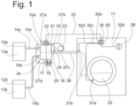
- a first embodiment of a dosing device 10a comprises a mixing distributor device 34 which - similar to the applicants' patent applications described at the outset - can consist of two disks, in particular an input disk 17 and an output disk 18, or comprises such disks 17, 18.
- the input disk 17 of the dosing device 10a is assigned a pair of input-side connections 15a, 15b. These are connected via media lines 14a, 14b to two containers 12a, 12b, on each of which a medium 13a, 13b is arranged.
- the medium is in particular a liquid, in particular a detergent, or a cleaning agent, or a disinfectant, or a component of one of the agents listed above, or an aid for a washing, or cleaning, or disinfection process.
- the media are in powder form or provided by a fluid.
- the number of media is arbitrary in the different embodiments. The same applies to the number of connected containers, the number of connections 15 on the input side of the dosing device 10a, and the number of outputs 16 on the output side of the respective dosing device 10, 10a.
- the dosing device 10a has only a single output connection 16, which connects the dosing device 10a to a target device 11 via a conveying line 26.
- this target device also serves as an example for other suitable target devices, such as commercial dishwashers, or other washing or cleaning or disinfection or processing or treatment facilities or systems or machines.
- the input disk 17 and the output disk 18 are rotatable relative to each other about a rotation axis 19.
- One disk 18 can be set in relative motion relative to the other disk 17 by a motor 20 which is only indicated schematically. Construction details are shown in Fig. 1 not shown, and are left to the expert, who can derive corresponding suggestions, for example, from the applicants' patent applications described at the beginning.
- the dosing device 10a has a control device 21, which is only indicated in block diagram form as a black box.
- the control unit 21 is connected to a communication interface 22 on the dosing device side via a signal or control line 27a.
- the communication interface 22 is in turn connected to a Fig. 1 shown communication line 25 is connected to the target device 11.
- the control unit 21 is also connected to a pump 23 via a control or signal line 27b.
- the control unit 21 can control the pump 23 via the signal line 27b and cause it to suck a certain amount of medium through the mixing distributor device 34 out of the respective container 12a or 12b and then convey it through the fluid line 26 to the target device 11.
- the control unit 21 is further connected to the motor 20 via the signal line 27d and can address the motor to cause one of the input-side terminals 15a, 15b to be communicatively connected to the output 26.
- a certain amount of medium 13a, 13b can be removed from the corresponding container 12a, 12b, that is, pumped out and at the same time pumped through the delivery line 26 to the target device 11.
- the control unit 21 is also connected via a signal line 27c to a schematically indicated sensor 24, or detector.
- the detector can be, for example, a flow meter, i.e. a flow measuring device, or alternatively a conductivity sensor. There could also be several, in Fig. 1 Detectors or sensors 24 (not shown) can be used, all of which can report their measurement results to the control unit 21.
- the control unit 21 is thus able to carry out or initiate dosing processes and to determine whether dosing processes have been carried out successfully. For example, such a determination as to whether a dosing process has been carried out correctly can depend on whether the control unit 21 receives corresponding, expected or possibly within an expected range of feedback after the motor 20 and/or pump 23 and/or a corresponding sensor 24 have responded. For example, in the event that the sensor 24 is designed as a conductivity measuring sensor, when the pump 23 responds and a certain medium 13a, 13b is conveyed, it can be expected that a certain conductivity will be detected by the conductivity measuring sensor at a certain point in time. If the expected conductivity is measured, the dosing process can be classified as completed or successful by the control unit 21.
- control unit 21 can be expected to pump a specific amount, i.e. a specific volume, of fluid through a specific measuring range, for example a measuring range of a flowmeter 24, when the pump 23 responds. If the control unit 21 detects a corresponding response signal from the flowmeter, or at least does not receive a corresponding interference signal from the connected unit 23, 24 or 20, the control unit 21 can assume that the dosing process to be carried out was successful or carried out correctly.
- control unit 21 receives corresponding interference signals or does not receive the expected feedback, it can assume that the dosing process has not taken place or has not been carried out successfully.
- the first communication interface 22 is designed and configured to transmit a corresponding signal or corresponding information about a completed dosing to the target device 11 via the communication line 25.
- the target device 11 has Fig. 1 a program selector switch 28 which enables the setting of a washing or cleaning program.
- This program selector switch is connected to a control unit 29 of the target device 11 via a signal line 32b.
- the control unit 29 corresponds, at least with regard to its block diagram function, to the control unit 21 of the dosing device 10a of the Fig. 1 .
- the control unit 29 is connected to a target device-side communication interface 30 via a signal line 32a. This is in turn connected to the signal or connection line or communication line 25.
- the control unit 29 is shown Fig. 1 furthermore connected to a sensor or detector 31b via a signal line 32d, and connected to a sensor or detector 31a via a signal line 32c.
- the two sensors 31a, 31b can, for example, determine or monitor the presence of liquid or medium, in particular the presence of water, or the presence of a certain conductivity, or temperature, or pH value, or a certain quantity, for example a maximum or minimum amount of liquid present, for example a fill level, and transmit corresponding measured values or measurement results to the control unit 29.
- the execution of a washing process and the transmission of dosing information can be carried out in one embodiment of the Fig. 1 for example, as follows: After a user has set a washing program on the target device 11 via the program selector switch 28, the control device 29 can use the second communication interface 30 to send a dosing request to the dosing device 10a. For example, in order to carry out a specific washing program, it may be required in a first step that the medium 13a is supplied in a predetermined amount at a predetermined time.
- the control unit 29 transmits this information via the second communication interface 30 and the connecting line 25 to the first communication interface 22 and to the control unit 21 of the dosing device 10a.
- the dosing device 10a can now initiate the corresponding dosing process and, by activating the motor 20 and subsequently activating the pump 23, initiate a corresponding delivery of the required amount of medium to the target device 11.
- a corresponding success signal can be transmitted via the communication interface 22 by feedback via the connecting line 25 to the communication interface 30 on the target device side.
- the control unit 29 can take note of the dosing success and then, in a second step, for example, make a subsequent dosing request or carry out a suitable measure on the target device itself, for example introducing fresh water, or increasing the temperature, or carrying out a washing drum rotation, etc.
- the control device 29 In the event that one of the sensors 31b, 31a in the target device 11 or the control device 29 detects the occurrence of any fault, for example that the water supply to the target device 11 is interrupted, or incorrect feedback values are received from the units connected to the control device 29, in particular the sensors 31a, 31b, information that a fault is present can be transmitted to the dosing device 10a. This can then, for example, interrupt the dosing process for this target device 11.
- control unit 21 determines after carrying out a dosing process that this is not has been properly completed, a corresponding signal is transmitted to the target device 11, or at least a signal indicating that dosing has been carried out successfully is not transmitted. From this, the control device 29 of the target device 11 can recognize or conclude that the dosing has not been carried out properly. Upon receipt and knowledge of this signal, the control device 29 can then initiate appropriate measures to ensure that no further subsequent problems arise. In particular, the control device 29 can, for example, interrupt the further washing process and/or initiate an appropriate acoustic or optical display for the user of the target device, which draws attention to the fact that an error has occurred during the dosing process.
- information can be exchanged about the manufacturer of the target device and/or the manufacturer of the dosing device. This allows the other device to adjust to the device, depending on the specifics of the manufacturer's information. For example, it can be stipulated that different manufacturers expect or take into account different special features when carrying out the washing or cleaning process, so that an optimized working method can be achieved.
- technical information about the target device and/or the dosing device can be transmitted. This includes, for example, information about a performance class of the target device or information about the possible number of different media or containers that can be connected or are connected to a dosing device and/or about the number of target devices that can be connected or are connected to a dosing device.
- the status of the target device and/or the status of the dosing device can be transmitted. This can ensure, for example, that dosing only actually takes place when the target device is in a corresponding status of a washing or cleaning process.
- information about the presence or absence of a fault on the target device and/or information about the presence or absence of a fault on the dosing device can be transmitted.
- the other device can take the status of the device into account and initiate appropriate measures with the aim of preventing a fault or preventing subsequent faults from occurring.
- the target device can transmit information about the washing program to be carried out to the dosing device. This can include information about the media to be used in the washing program or cleaning program to be carried out and the times at which they are to be used. There is also the possibility, particularly in the case that several target devices are connected to the dosing device, that the dosing device can Goals of optimized dosing overall, decides for itself when to carry out certain dosing processes.
- it can be designed to handle the prioritization of conflicting dosing requests. In particular, it can be further designed to prevent such a possible collision of conflicting dosing requests in advance. This can be done, for example, by the dosing device transmitting information to the corresponding target device or, if necessary, to several target devices that dosing will be ready at certain times. The target device can then adapt or optimize its own washing and/or cleaning process based on knowledge of the operating status of the dosing device or on knowledge of a soon-to-be-expected, possibly changing operating status of the dosing device.
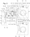
- the metering device designated there with 10b has two mixing distributor devices 34a and 34b. These are connected to one another via an intermediate line 35 and are arranged geometrically inverted to one another.
- the first mixing distribution device 34b has an input disk 17a with three connections 15a, 15b, 15c, and an output disk 18a that can be rotated relative thereto and can be controlled via a motor 20b.
- the only output 16d is connected via the intermediate line 35 to the only input 15d of the second mixing distribution device 34a. Its input disk 17b can be rotated about the axis of rotation 19, i.e. relative to the second output disk 18b, via the second motor 20a.
- Three output connections 16a, 16b, 16c are connected to the output disk 18b.
- Fluid delivery lines 26a, 26b are only shown for the two output connections 16a, 16c, which lead to corresponding target devices 11a, 11b.
- a first pump 23a is connected to the first fluid line 26a and a second pump 23b is connected to the second fluid line 26b.
- the target device that can be connected to the third connection line 26c is in Fig. 2 not shown for the sake of clarity.
- control unit 21 is designed to carry out a control via the several signal lines 27a, 27b, 27c, 27d, 27e, 27f, which functions approximately as follows:
- a dosing request is received from a corresponding target device 11a or 11b via the corresponding signal line 25a or 25b
- a corresponding fluid connection is first established between the relevant container 12a, 12b, 12c and the corresponding delivery line 26a and 26b by activating the two motors 20a, 20b.
- the specified delivery quantity of volume is then delivered to the corresponding target device 11a or 11b by activating the respective pump 23a or 23b.
- only a single pump 23c can be provided in the region of the intermediate line 35, as shown in dashed lines.
- control unit 21 can contain an integrated or separate device 36 for collision prevention, which ensures, for example, that if a dosing process has begun, this is first completed before a second dosing process requested at the same time as the first dosing process is carried out is started and processed.
- an importance scale can be introduced - and used when processing dosing processes - which takes into account, for example, that certain target devices should not or may not pause for an indefinite length of time, at least at certain times during certain washing or cleaning processes.
- dosing processes could be brought forward under certain circumstances, including the possibility that dosing processes that have already begun are aborted and paused in order to be continued again later, after a second dosing process has been carried out.
- the dosing device 10b or the The collision prevention device 36 integrated in the control unit 21 ensures that the target device that has a lower priority, i.e. that has to wait a little, for example, is informed that the dosing process cannot or will only begin later, for example a few minutes later.
- the control unit 21 or the communication interface 22 can transmit a corresponding collision signal via the respective connecting line 25a, 25b to the respective control device 29a, 29b, or to the respective target device-side communication interface 30a, 30b of the target device 11a, 11b.
- the corresponding target device 11a, 11b After receiving corresponding collision information, the corresponding target device 11a, 11b can adjust to it, and the control device 29a, 29b connected to the corresponding target device 11a, 11b can initiate a corresponding measure on the corresponding target device 11a, 11b if necessary.
- the mixing distributor device designated 34a in the Fig. 2 illustrated embodiment is designed such that when a communication path is provided between the input connection 15d of the input disk 17b and one of the output connections 16a, 16b, 16c of the output disk 18b, for example the output connection 16a, the remaining output connections 16b, 16c are blocked.
- the second mixing distributor device 34a is designed such that the output connections (for example 16b, 16c) that are not connected to the input connection 15d are not blocked, but remain open after the corresponding flushing of the associated fluid delivery line 26b, 26c.
- the output connections for example 16b, 16c
- a first mixing distributor device 34a has an input disk 17a and an output disk 18a.
- the input disk 17a has - for the sake of simplicity - only one input connection 15a
- the output disk 18a has - also for the sake of simplicity - only two output connections 16a, 16b.
- the output connection 16a is connected to a second mixing distribution device 34b via a first intermediate line 35a and the second connection 16b is connected to a third mixing distribution device 34c via a second intermediate line 35b.
- the second mixing distributor device 34b also has an input disk 17b and an output disk 18b, which are rotatable relative to each other about a rotation axis 19b.
- the third mixing distributor device 34c has a first input disk 17c and a second output disk 18c, which are rotatable relative to each other about a rotation axis 19c.
- Each of the two output disks 18b, 18c has three output connections 16c, 16d, 16e and 16f, 16g, 16h.
- Fig. 3 it is possible to connect a plurality of, in the present embodiment, Fig. 3 , a total of six target devices can be connected. For the sake of clarity, Fig. 3 but only two target devices 11a and 11f are shown.
- the dosing device 10c can also control or prevent a collision of simultaneous dosing requests from different target devices 11a, 11f via the communication interface 22 by means of the collision prevention device 36 integrated in the control unit 21.
- Fig. 3 shows a cascade of mixing distribution devices 34a, 34b, 34c with the result that a plurality of target devices 11a, 11b can be supplied with one medium or with different media by means of a single dosing device 10c.
- the embodiment of the Fig. 3 also includes variants in which a plurality of containers, in particular a plurality of different media, are connected to the dosing device 10.
- the device 36 for preventing collisions can be an integral part of the corresponding control unit 21 on the dosing device 10, or can also be designed separately from this.
- the device 36 for preventing collisions can be formed by a microprocessor or be part of the control unit 21 of the dosing device 10, 10a, 10b, 10c.
Landscapes
- Engineering & Computer Science (AREA)
- Textile Engineering (AREA)
- Devices For Dispensing Beverages (AREA)
- Loading And Unloading Of Fuel Tanks Or Ships (AREA)
- Detail Structures Of Washing Machines And Dryers (AREA)
Applications Claiming Priority (3)
| Application Number | Priority Date | Filing Date | Title |
|---|---|---|---|
| DE102015107976.3A DE102015107976A1 (de) | 2015-05-20 | 2015-05-20 | Dosiereinrichtung u.a. |
| EP20186553.2A EP3754089B1 (fr) | 2015-05-20 | 2016-05-18 | Dispositif de dosage |
| EP16001125.0A EP3095907B1 (fr) | 2015-05-20 | 2016-05-18 | Dispositif de dosage |
Related Parent Applications (3)
| Application Number | Title | Priority Date | Filing Date |
|---|---|---|---|
| EP20186553.2A Division EP3754089B1 (fr) | 2015-05-20 | 2016-05-18 | Dispositif de dosage |
| EP20186553.2A Division-Into EP3754089B1 (fr) | 2015-05-20 | 2016-05-18 | Dispositif de dosage |
| EP16001125.0A Division EP3095907B1 (fr) | 2015-05-20 | 2016-05-18 | Dispositif de dosage |
Publications (2)
| Publication Number | Publication Date |
|---|---|
| EP4516985A2 true EP4516985A2 (fr) | 2025-03-05 |
| EP4516985A3 EP4516985A3 (fr) | 2025-04-23 |
Family
ID=56120884
Family Applications (3)
| Application Number | Title | Priority Date | Filing Date |
|---|---|---|---|
| EP20186553.2A Active EP3754089B1 (fr) | 2015-05-20 | 2016-05-18 | Dispositif de dosage |
| EP16001125.0A Active EP3095907B1 (fr) | 2015-05-20 | 2016-05-18 | Dispositif de dosage |
| EP25150305.8A Pending EP4516985A3 (fr) | 2015-05-20 | 2016-05-18 | Dispositif de dosage |
Family Applications Before (2)
| Application Number | Title | Priority Date | Filing Date |
|---|---|---|---|
| EP20186553.2A Active EP3754089B1 (fr) | 2015-05-20 | 2016-05-18 | Dispositif de dosage |
| EP16001125.0A Active EP3095907B1 (fr) | 2015-05-20 | 2016-05-18 | Dispositif de dosage |
Country Status (3)
| Country | Link |
|---|---|
| EP (3) | EP3754089B1 (fr) |
| DE (1) | DE102015107976A1 (fr) |
| ES (2) | ES2828926T3 (fr) |
Families Citing this family (32)
| Publication number | Priority date | Publication date | Assignee | Title |
|---|---|---|---|---|
| DE102015110862B4 (de) * | 2015-07-06 | 2019-03-07 | Beatrice Saier | Dosiereinrichtung zur Dosierung und Zuführung von Medien und Verfahren |
| DE102016102829A1 (de) | 2016-02-18 | 2017-08-24 | Beatrice Saier | Dosiereinrichtung und Verfahren zum Betreiben einer Dosiereinrichtung |
| WO2017162291A1 (fr) | 2016-03-24 | 2017-09-28 | Electrolux Appliances Aktiebolag | Machine à laver comprenant un dispositif d'adoucissement d'eau et une unité de commande électronique locale |
| DE102017103168B3 (de) | 2016-11-08 | 2018-03-01 | Beatrice Saier | Dosiereinrichtung |
| DE102016225854A1 (de) * | 2016-12-21 | 2018-06-21 | Henkel Ag & Co. Kgaa | Nachrüstbare Sensoreinheit zur Steuerung einer Dosiervorrichtung |
| DE102016225828A1 (de) | 2016-12-21 | 2018-06-21 | Henkel Ag & Co. Kgaa | Verfahren zur Dosierung von Reinigungsmitteln |
| DE102016125928A1 (de) | 2016-12-30 | 2018-07-05 | Beatrice Saier | Dosiereinrichtung und Verfahren zum Betreiben einer Dosiereinrichtung |
| PL3348700T3 (pl) * | 2017-01-12 | 2021-10-04 | Electrolux Appliances Aktiebolag | Urządzenie gospodarstwa domowego zawierające moduł dopływu wody |
| DE102017114767A1 (de) | 2017-04-04 | 2018-10-04 | Beatrice Saier | Dosiereinrichtung und Verfahren zum Betreiben einer Dosiereinrichtung |
| DE102017114665A1 (de) | 2017-06-30 | 2019-01-03 | Beatrice Saier | Dosiereinrichtung u.a. |
| DE102017215258A1 (de) * | 2017-08-31 | 2019-02-28 | BSH Hausgeräte GmbH | Wäschepflegegerät mit einem Dosiermodul |
| CN111247283B (zh) * | 2017-10-25 | 2023-05-30 | E.G.O.电气设备制造股份有限公司 | 洗衣机贮槽、洗衣机和用于操作洗衣机的方法 |
| DE102018113644A1 (de) | 2018-06-07 | 2019-12-12 | Beatrice Saier | Dosiereinrichtung |
| CN110656469B (zh) * | 2018-06-29 | 2021-05-18 | 杭州神林电子有限公司 | 洗涤剂投放器 |
| DE102019135125A1 (de) * | 2019-12-19 | 2021-06-24 | Miele & Cie. Kg | Einrichtung zum Zuführen von Behandlungsmittel für eine Waschmaschine und Waschmaschine |
| DE102020113828A1 (de) | 2020-02-13 | 2021-08-19 | Beatrice Saier | Sauglanze |
| EP3865831B1 (fr) | 2020-02-13 | 2024-03-20 | Herbert Saier GmbH | Lance d'aspiration |
| DE102020118060B3 (de) | 2020-06-12 | 2021-09-09 | Beatrice Saier | Dosiereinrichtung |
| DE102020116298A1 (de) | 2020-06-19 | 2021-12-23 | Beatrice Saier | Pulver-Dosiereinrichtung |
| EP4162856A1 (fr) | 2021-10-07 | 2023-04-12 | Michael Saier | Dispositif de dosage |
| DE102022116396A1 (de) | 2022-06-02 | 2023-12-07 | Beatrice Saier | Dosiereinrichtung zur Dosierung pulverförmiger oder feststoffartiger Medien |
| DE102022117015A1 (de) | 2022-07-07 | 2024-01-18 | Herbert Saier GmbH Elektrische Steuerungen | Sauglanze |
| EP4306913A1 (fr) | 2022-07-14 | 2024-01-17 | Herbert Saier GmbH | Dispositif de raccordement |
| DE102022126804A1 (de) | 2022-07-14 | 2024-01-25 | Herbert Saier GmbH Elektrische Steuerungen | Anschlussvorrichtung |
| DE102022117813A1 (de) | 2022-07-15 | 2024-01-18 | Herbert Saier GmbH Elektrische Steuerungen | Vorrichtung zur Bereitstellung einer Medienlösung |
| DE102023108275A1 (de) | 2023-03-31 | 2024-10-02 | Herbert Saier Gmbh | Dosiereinrichtung |
| EP4636152A1 (fr) | 2024-04-18 | 2025-10-22 | Herbert Saier GmbH | Dispositif de dosage |
| DE102024119640A1 (de) * | 2024-07-03 | 2026-01-08 | Herbert Saier Gmbh | Dosiereinrichtung |
| EP4675032A3 (fr) | 2024-07-03 | 2026-02-25 | Herbert Saier GmbH | Dispositif de dosage |
| DE102024120420A1 (de) * | 2024-07-18 | 2026-01-22 | Herbert Saier Gmbh | Dosiereinrichtung |
| DE102024120607A1 (de) * | 2024-07-19 | 2026-01-22 | Herbert Saier Gmbh | Dosiereinrichtung |
| DE102024120873A1 (de) * | 2024-07-23 | 2026-01-29 | Herbert Saier Gmbh | Dosiereinrichtung |
Citations (3)
| Publication number | Priority date | Publication date | Assignee | Title |
|---|---|---|---|---|
| EP1181567A1 (fr) | 1999-04-21 | 2002-02-27 | Sunrise Telecom, Inc. | Detection points de raccordement par analyse de domaine de frequence |
| DE102011108396A1 (de) | 2010-07-28 | 2012-06-28 | Beatrice Saier | Vorrichtung zur Dosierung und Mischung von Fluiden-Mischverteiler |
| DE102011119021B3 (de) | 2011-11-22 | 2013-05-16 | Beatrice Saier | Vorrichtung und Verfahren zum schaltbaren Verbinden |
Family Cites Families (7)
| Publication number | Priority date | Publication date | Assignee | Title |
|---|---|---|---|---|
| DE3907361A1 (de) * | 1989-03-08 | 1990-09-20 | Henkel Kgaa | Pulverdosiergeraet |
| US5014211A (en) * | 1989-06-16 | 1991-05-07 | Diversey Corporation | Microprocessor controlled liquid chemical delivery system and method |
| US5897671A (en) * | 1997-11-07 | 1999-04-27 | Diversey Lever, Inc. | System and method for washing machine cycle identification and chemical dosing identification |
| US6375935B1 (en) | 2000-04-28 | 2002-04-23 | Brent R. Constantz | Calcium phosphate cements prepared from silicate solutions |
| DE10114256A1 (de) * | 2001-03-22 | 2002-10-02 | Henkel Kgaa | Dosiersystem für Waschsubstanzen |
| DE202008001532U1 (de) * | 2008-02-01 | 2008-04-10 | Weber, Lothar Ernst Wilhelm | Vorrichtung zum Waschen oder Reinigen von Gegenständen |
| US9447536B2 (en) * | 2011-10-14 | 2016-09-20 | Delaware Capital Formation, Inc. | Intelligent network for chemical dispensing system |
-
2015
- 2015-05-20 DE DE102015107976.3A patent/DE102015107976A1/de active Pending
-
2016
- 2016-05-18 EP EP20186553.2A patent/EP3754089B1/fr active Active
- 2016-05-18 EP EP16001125.0A patent/EP3095907B1/fr active Active
- 2016-05-18 ES ES16001125T patent/ES2828926T3/es active Active
- 2016-05-18 ES ES20186553T patent/ES3018135T3/es active Active
- 2016-05-18 EP EP25150305.8A patent/EP4516985A3/fr active Pending
Patent Citations (3)
| Publication number | Priority date | Publication date | Assignee | Title |
|---|---|---|---|---|
| EP1181567A1 (fr) | 1999-04-21 | 2002-02-27 | Sunrise Telecom, Inc. | Detection points de raccordement par analyse de domaine de frequence |
| DE102011108396A1 (de) | 2010-07-28 | 2012-06-28 | Beatrice Saier | Vorrichtung zur Dosierung und Mischung von Fluiden-Mischverteiler |
| DE102011119021B3 (de) | 2011-11-22 | 2013-05-16 | Beatrice Saier | Vorrichtung und Verfahren zum schaltbaren Verbinden |
Also Published As
| Publication number | Publication date |
|---|---|
| EP4516985A3 (fr) | 2025-04-23 |
| EP3095907B1 (fr) | 2020-09-02 |
| EP3754089A1 (fr) | 2020-12-23 |
| EP3095907A1 (fr) | 2016-11-23 |
| EP3754089B1 (fr) | 2025-03-26 |
| ES3018135T3 (en) | 2025-05-14 |
| ES2828926T3 (es) | 2021-05-28 |
| EP3754089C0 (fr) | 2025-03-26 |
| DE102015107976A1 (de) | 2016-11-24 |
Similar Documents
| Publication | Publication Date | Title |
|---|---|---|
| EP3095907B1 (fr) | Dispositif de dosage | |
| EP3091114B2 (fr) | Systeme de dosage de milieux pour installations de lavage et/ou de nettoyage | |
| EP3115498B1 (fr) | Dispositif de dosage destine au dosage et a l'introduction de milieux et procede | |
| EP2913431B1 (fr) | Système de détection de la consommation d'un fluide dans une installation de nettoyage ou de lavage ou similaire | |
| DE102018113644A1 (de) | Dosiereinrichtung | |
| DE102017200481B4 (de) | Verfahren zu einem Betrieb eines Schmierstoffverteilsystem | |
| EP3319061A1 (fr) | Dispositif de dosage | |
| EP3343186A2 (fr) | Dispositif de dosage et son procédé de fonctionnement | |
| DE102011014142A1 (de) | Fahrzeugsteuervorrichtung für eine CAN-Kommunikation und Diagnoseverfahren hierfür | |
| EP3866650B1 (fr) | Machine de préparation de boissons | |
| DE102014101079A1 (de) | Verfahren zum Betrieb einer Küchenmaschine und Küchenmaschine | |
| DE112012004029T5 (de) | Slave-Vorrichtung, Master-Vorrichtung und Kommunikationsverfahren | |
| DE112018002555T5 (de) | Automatische USB-Host-zu-Host-Umschaltung | |
| DE102011081640A1 (de) | Steuersystem | |
| DE102020118060B3 (de) | Dosiereinrichtung | |
| DE19649577B4 (de) | Kommunikationssystem | |
| WO2016026620A1 (fr) | Procédé de test d'un appareil de terrain | |
| EP2143366A1 (fr) | Procédé de dosage d'un premier moyen de traitement et d'un second moyen de traitement dans le récipient de nettoyage d'un lave-vaisselle | |
| DE102024110795A1 (de) | Filtervorrichtung für ein Reinigungsgerät, Verfahren und Vorrichtung zum Betreiben zumindest eines Reinigungsgerätes im Zusammenhang mit einer Filtervorrichtung und Reinigungssystem | |
| DE102010029839B4 (de) | Steuersystem | |
| DE10155886B4 (de) | Automatisierbare Mess-, Reinigungs-und/oder Kalibriereinrichtung für Elektroden zur Messung von ph-Werten oder Redoxpotentialen | |
| DE202017100160U1 (de) | Schmierstoffverteilsystem | |
| BE1031619B1 (de) | Filtervorrichtung für ein Reinigungsgerät, Verfahren und Vorrichtung zum Betreiben zumindest eines Reinigungsgerätes im Zusammenhang mit einer Filtervorrichtung und Reinigungssystem | |
| DE102020104083A1 (de) | Verfahren zur Prüfung eines Systemzustands eines mechatronischen Systems eines Fahrzeuges | |
| EP4512285A1 (fr) | Machine à café automatique avec un affichage comprenant une zone de pré/avertissement et produit de programme informatique |
Legal Events
| Date | Code | Title | Description |
|---|---|---|---|
| PUAI | Public reference made under article 153(3) epc to a published international application that has entered the european phase |
Free format text: ORIGINAL CODE: 0009012 |
|
| STAA | Information on the status of an ep patent application or granted ep patent |
Free format text: STATUS: THE APPLICATION HAS BEEN PUBLISHED |
|
| AC | Divisional application: reference to earlier application |
Ref document number: 3095907 Country of ref document: EP Kind code of ref document: P Ref document number: 3754089 Country of ref document: EP Kind code of ref document: P |
|
| AK | Designated contracting states |
Kind code of ref document: A2 Designated state(s): AL AT BE BG CH CY CZ DE DK EE ES FI FR GB GR HR HU IE IS IT LI LT LU LV MC MK MT NL NO PL PT RO RS SE SI SK SM TR |
|
| REG | Reference to a national code |
Ref country code: DE Ref legal event code: R079 Free format text: PREVIOUS MAIN CLASS: D06F0039020000 Ipc: D06F0033370000 |
|
| PUAL | Search report despatched |
Free format text: ORIGINAL CODE: 0009013 |
|
| AK | Designated contracting states |
Kind code of ref document: A3 Designated state(s): AL AT BE BG CH CY CZ DE DK EE ES FI FR GB GR HR HU IE IS IT LI LT LU LV MC MK MT NL NO PL PT RO RS SE SI SK SM TR |
|
| RIC1 | Information provided on ipc code assigned before grant |
Ipc: D06F 105/42 20200101ALN20250320BHEP Ipc: D06F 103/00 20200101ALN20250320BHEP Ipc: A47L 15/00 20060101ALN20250320BHEP Ipc: A47L 15/44 20060101ALN20250320BHEP Ipc: D06F 39/02 20060101ALI20250320BHEP Ipc: D06F 33/37 20200101AFI20250320BHEP |
|
| STAA | Information on the status of an ep patent application or granted ep patent |
Free format text: STATUS: REQUEST FOR EXAMINATION WAS MADE |
|
| 17P | Request for examination filed |
Effective date: 20250903 |