EP4520498A2 - Coffrage servant à la fabrication d'un segment de cuvelage en béton d'un système d'aménagement pour tunnel - Google Patents
Coffrage servant à la fabrication d'un segment de cuvelage en béton d'un système d'aménagement pour tunnel Download PDFInfo
- Publication number
- EP4520498A2 EP4520498A2 EP25154557.0A EP25154557A EP4520498A2 EP 4520498 A2 EP4520498 A2 EP 4520498A2 EP 25154557 A EP25154557 A EP 25154557A EP 4520498 A2 EP4520498 A2 EP 4520498A2
- Authority
- EP
- European Patent Office
- Prior art keywords
- formwork
- wall
- walls
- base
- closed position
- Prior art date
- Legal status (The legal status is an assumption and is not a legal conclusion. Google has not performed a legal analysis and makes no representation as to the accuracy of the status listed.)
- Pending
Links
Images


Classifications
-
- B—PERFORMING OPERATIONS; TRANSPORTING
- B25—HAND TOOLS; PORTABLE POWER-DRIVEN TOOLS; MANIPULATORS
- B25J—MANIPULATORS; CHAMBERS PROVIDED WITH MANIPULATION DEVICES
- B25J11/00—Manipulators not otherwise provided for
-
- B—PERFORMING OPERATIONS; TRANSPORTING
- B25—HAND TOOLS; PORTABLE POWER-DRIVEN TOOLS; MANIPULATORS
- B25J—MANIPULATORS; CHAMBERS PROVIDED WITH MANIPULATION DEVICES
- B25J5/00—Manipulators mounted on wheels or on carriages
- B25J5/02—Manipulators mounted on wheels or on carriages travelling along a guideway
- B25J5/04—Manipulators mounted on wheels or on carriages travelling along a guideway wherein the guideway is also moved, e.g. travelling crane bridge type
-
- B—PERFORMING OPERATIONS; TRANSPORTING
- B25—HAND TOOLS; PORTABLE POWER-DRIVEN TOOLS; MANIPULATORS
- B25J—MANIPULATORS; CHAMBERS PROVIDED WITH MANIPULATION DEVICES
- B25J9/00—Program-controlled manipulators
- B25J9/0009—Constructional details, e.g. manipulator supports, bases
-
- B—PERFORMING OPERATIONS; TRANSPORTING
- B28—WORKING CEMENT, CLAY, OR STONE
- B28B—SHAPING CLAY OR OTHER CERAMIC COMPOSITIONS; SHAPING SLAG; SHAPING MIXTURES CONTAINING CEMENTITIOUS MATERIAL, e.g. PLASTER
- B28B11/00—Apparatus or processes for treating or working the shaped or preshaped articles
- B28B11/24—Apparatus or processes for treating or working the shaped or preshaped articles for curing, setting or hardening
- B28B11/245—Curing concrete articles
-
- B—PERFORMING OPERATIONS; TRANSPORTING
- B28—WORKING CEMENT, CLAY, OR STONE
- B28B—SHAPING CLAY OR OTHER CERAMIC COMPOSITIONS; SHAPING SLAG; SHAPING MIXTURES CONTAINING CEMENTITIOUS MATERIAL, e.g. PLASTER
- B28B15/00—General arrangement or layout of plant ; Industrial outlines or plant installations
- B28B15/002—Mobile plants, e.g. on vehicles or on boats
-
- B—PERFORMING OPERATIONS; TRANSPORTING
- B28—WORKING CEMENT, CLAY, OR STONE
- B28B—SHAPING CLAY OR OTHER CERAMIC COMPOSITIONS; SHAPING SLAG; SHAPING MIXTURES CONTAINING CEMENTITIOUS MATERIAL, e.g. PLASTER
- B28B17/00—Details of, or accessories for, apparatus for shaping the material; Auxiliary measures taken in connection with such shaping
- B28B17/0063—Control arrangements
- B28B17/0081—Process control
-
- B—PERFORMING OPERATIONS; TRANSPORTING
- B28—WORKING CEMENT, CLAY, OR STONE
- B28B—SHAPING CLAY OR OTHER CERAMIC COMPOSITIONS; SHAPING SLAG; SHAPING MIXTURES CONTAINING CEMENTITIOUS MATERIAL, e.g. PLASTER
- B28B5/00—Producing shaped articles from the material in moulds or on moulding surfaces, carried or formed by, in or on conveyors irrespective of the manner of shaping
- B28B5/04—Producing shaped articles from the material in moulds or on moulding surfaces, carried or formed by, in or on conveyors irrespective of the manner of shaping in moulds moved in succession past one or more shaping stations
-
- B—PERFORMING OPERATIONS; TRANSPORTING
- B28—WORKING CEMENT, CLAY, OR STONE
- B28B—SHAPING CLAY OR OTHER CERAMIC COMPOSITIONS; SHAPING SLAG; SHAPING MIXTURES CONTAINING CEMENTITIOUS MATERIAL, e.g. PLASTER
- B28B7/00—Moulds; Cores; Mandrels
- B28B7/0002—Auxiliary parts or elements of the mould
- B28B7/0014—Fastening means for mould parts, e.g. for attaching mould walls on mould tables; Mould clamps
-
- B—PERFORMING OPERATIONS; TRANSPORTING
- B28—WORKING CEMENT, CLAY, OR STONE
- B28B—SHAPING CLAY OR OTHER CERAMIC COMPOSITIONS; SHAPING SLAG; SHAPING MIXTURES CONTAINING CEMENTITIOUS MATERIAL, e.g. PLASTER
- B28B7/00—Moulds; Cores; Mandrels
- B28B7/0029—Moulds or moulding surfaces not covered by B28B7/0058 - B28B7/36 and B28B7/40 - B28B7/465, e.g. moulds assembled from several parts
- B28B7/0035—Moulds characterised by the way in which the sidewalls of the mould and the moulded article move with respect to each other during demoulding
- B28B7/0044—Moulds characterised by the way in which the sidewalls of the mould and the moulded article move with respect to each other during demoulding the sidewalls of the mould being only tilted away from the sidewalls of the moulded article, e.g. moulds with hingedly mounted sidewalls
-
- B—PERFORMING OPERATIONS; TRANSPORTING
- B28—WORKING CEMENT, CLAY, OR STONE
- B28B—SHAPING CLAY OR OTHER CERAMIC COMPOSITIONS; SHAPING SLAG; SHAPING MIXTURES CONTAINING CEMENTITIOUS MATERIAL, e.g. PLASTER
- B28B7/00—Moulds; Cores; Mandrels
- B28B7/38—Treating surfaces of moulds, cores, or mandrels to prevent sticking
- B28B7/386—Cleaning
-
- E—FIXED CONSTRUCTIONS
- E21—EARTH OR ROCK DRILLING; MINING
- E21D—SHAFTS; TUNNELS; GALLERIES; LARGE UNDERGROUND CHAMBERS
- E21D11/00—Lining tunnels, galleries or other underground cavities, e.g. large underground chambers; Linings therefor; Making such linings in situ, e.g. by assembling
- E21D11/04—Lining with building materials
- E21D11/08—Lining with building materials with preformed concrete slabs
- E21D11/086—Methods of making concrete lining segments
Definitions
- the invention relates to a formwork for producing a concrete segment of a tunnel lining system, comprising a concrete trough for receiving a quantity of concrete required to produce the segment and, if necessary, for receiving the intended reinforcement of the concrete segment, wherein the concrete trough has at least one base and walls adapted to the base, wherein at least one wall is detachable from the base and pivotable relative to the base between a closed position and an open position,
- Such formwork is preferably used in a production plant for the manufacture of the concrete segment of the tunnel lining system for the production of the concrete segment.
- the object of the invention is therefore to reduce at least partial aspects of the problems mentioned above.
- the formwork has at least one drive system for pivoting the at least one wall between the open and the closed position and for holding it in the respective position, and in that the drive system has at least one actuator for pivoting the at least one wall between the open and the closed position.
- a further teaching of the invention provides that at least two walls touch each other at one of their two outer end regions with their short sides in the closed position, thereby forming a corner of the concrete trough. It is advantageous that a male engagement element is provided on one of the two walls in the outer end region and a female engagement element is provided on the other wall in the outer end region, which engage with each other when the two walls are in the closed position. This makes it easy to ensure the corner is closed.
- the two walls are connected to one another in their outer end regions by means of at least one screw connection or a clamp connection, wherein the screw connection or clamp connection preferably serves to secure the position, and/or wherein the screw connection comprises a screw with a spring element arranged along at least part of the screw.
- the clamping connection has a locking element that is arranged on one of the wall elements and is pivotally movable between an open and a closed position by at least one actuator, for example, a hydraulic cylinder or a spindle system. It is advantageous that the actuator is connected to the drive system described below. This allows for a simple securing mechanism.
- a further teaching of the invention provides that the at least one wall is connected to at least two actuators of the drive system for movement between the open and closed positions. This allows the necessary holding forces to be applied and distributed in a simple manner.
- a further teaching of the invention provides that the at least one wall element has two outer end regions, and that at least one actuator is provided for each end region to move and hold the wall element. It has been shown that this makes it particularly easy to ensure a tight seal, even when the formwork is filled with concrete and the side walls are possibly deformed as a result.
- a further teaching of the invention provides that the drive system can be connected to an external drive at a workstation for driving the drive system. This allows the assembly of the formwork to be as simple as possible, since a drive in the formwork is eliminated.
- a further teaching of the invention provides that the drive system is a hydraulic system with at least one hydraulic circuit, wherein the drive system has at least one hydraulic cylinder as an actuator connected to the hydraulic circuit. This allows both movement and holding to be provided with sufficient forces in a simple manner.
- the hydraulic circuit has a blocking element for maintaining the pressure in the hydraulic circuit, which is preferably a load-bearing valve. It is further advantageous that the hydraulic circuit has an element for compensating for a pressure change and/or a volume change in the hydraulic circuit, which is preferably a dummy cylinder or a diaphragm accumulator. It is further advantageous that the hydraulic circuit has at least one connection element for detachably connecting the hydraulic circuit to a hydraulic unit as an external drive of the drive system at a work station. It is also advantageous that the individual hydraulic cylinders are connected by means of pressure sequence valves. This makes it possible to easily control the sequence of the individual steps of opening and/or closing the formwork.
- a hydraulic circuit according to the invention can be easily provided by at least one of the aforementioned elements.
- the drive system is a mechanical drive as an actuator, preferably a spindle drive. It is advantageous for the mechanical drive to be self-locking or to be provided with a locking element. It is further advantageous for the mechanical drive to have a connecting element for detachable connection to an external rotary drive, for example, a torque screwdriver, as the external drive of the drive system at a workstation.
- a further teaching of the invention provides that at least one pivotable cover element is provided on the formwork, which can be arranged on the upper side of the concrete trough and at least partially covers the upper side. It is advantageous that the cover element is pivotable between an open and a closed position by at least one actuator, for example a hydraulic cylinder or a spindle system, which preferably holds the cover element in the respective position. It is further advantageous that the actuator is connected to the previously described drive system.
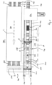
- Figures 1 to 4 show a production plant 100 for concrete segments 500 in which a formwork 10 according to the invention is used.
- the production plant 100 is designed, for example, as a circulation plant for the formwork 10.
- the formwork according to the invention can also be used in a stationary plant (not shown), in which the formwork remains in one location for the production steps before being introduced into a hardening plant for the accelerated initial hardening of the concrete segment 500, if such hardening is necessary.
- the circulation system consists of a production line 200 and a hardening tunnel 300.
- the hardening tunnel 300 has at least one hardening line 310, in Figure 1 shown are three hardening lines 310.
- the production line 200 and the hardening tunnel 300 or its hardening lines 310 are connected by a cross conveyor 400.
- the production facility 100 has a transport path 110.
- the transport path 110 has a track 111 on which a transport means 112 can travel.
- a formwork 10 according to the invention is arranged on the transport means 112.
- the transport means 112 move along the transport path 110 in the direction of arrow A through the production line 200.
- the cross conveyor 400 After passing through the production line 200, they are fed by the cross conveyor 400 in the direction of arrow B to the hardening lines 320 of the hardening tunnel 300.
- the cross conveyor 400 also has a track 111 on which the transport means 112 are moved. The same applies to the hardening lines 320 of the hardening tunnel 300.
- the transport means 112 After passing through the hardening tunnel 300 in the direction of arrow C, the transport means 112 are returned to the production line 200 by means of the cross conveyor 400 in the direction of arrow D. The circulation is then completed.
- the production line 200 has six workstations 210 - 260.
- the formwork 10 is opened as explained below.
- the finished segment 500 is removed from the formwork 10 by means of a lifting element (not shown).
- the formwork 10 is cleaned and prepared for the insertion of the installed elements and for concreting.
- a release agent formwork oil
- a release agent is applied, for example, to all surfaces and parts of the formwork that will come into contact with the concrete of the segment 500 to be produced and are not intended to become part of the segment 500.
- the formwork 10 is equipped with the components that are part of the finished segment 500. These include, for example, reinforcement 510, electrical anchors (not shown), a protective liner, or the like.
- the formwork 10 is checked with the inserted components to ensure that the formwork 10 is correctly assembled and the built-in components of the segment 500 are correctly arranged.
- the assembly of the formwork 10 with the components can also be carried out in the work stations 230, 240.
- any formwork covers (not shown) are installed, the concrete to be poured is prepared according to the required mix and in the required quantity, and poured into the formwork 10. The poured concrete is then compacted in the known manner. Pouring and compacting can be performed alternately until the required amount of concrete has been poured.
- the concrete surface 520 of the segment is treated, for example, by smoothing. Any covers are removed before smoothing.
- the production line 200 is then left after the sixth work station 260 in this example, in which the transport means 112 with the formwork 10 and the raw segment 500 completely produced therein is transferred to the cross conveyor 400.
- the number of workstations shown here is only an example. A specialist can easily adjust the number of workstations as needed by combining or decoupling individual work steps.
- a first embodiment of the formwork 10 (see Fig. 5 to 10 ) is arranged, for example, above a base 11 of the transport means 112.
- the formwork itself has a base 12 with which it can be arranged on the base 11.
- an interior space 17 is provided as a concrete trough, which is formed from a floor 16 and inner walls of the end walls 15 and side walls 14. The built-in components and the concrete are introduced into this concrete trough or into this interior space 17.
- the base 12 is pivotally connected, in a non-limiting manner, to two side walls 14 of the formwork 10 via pivot connections 13.
- the formwork 10 has two end walls 15.
- the end walls 15 are firmly connected to the base 12. It is equally possible here for the end walls 15 to be firmly pivotably connected to the base 12 via articulated connections.
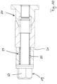
- the side walls 14 are connected to the base 12 and the end walls 15 via screw connections.
- a screw connection is shown in Figure 10 It has a screw 19 that is screwed into a threaded element 20 arranged on the base 12 or, for example, on the end wall 15.
- the screw 19 is inserted into a sleeve 21 that is attached, for example, to the side wall 14 above a through opening (not shown).
- the sleeve 21 has a spring portion 22 in which a spring 23 is provided.
- the screw 19 can be screwed into the threaded element 20 and thus lock the side wall 14 against the base 12 and/or the end wall 15.
- a drive system is provided that enables the movement of the side walls 14 against the base 12 and/or the end walls 15, or alternatively, the floor 16.
- this can be a spindle system as a mechanical drive that, when driven, rotates the side walls 14 around the pivot connection 13 in the double arrow direction G either away from the base 12 and the end walls 15 and the floor 16 or towards them.
- other drive systems such as hydraulic cylinders, can also be used for this purpose.
- a further embodiment with a hydraulic drive system is explained in a second embodiment of the invention, but can also be used alternatively in the first embodiment.
- a mechanical drive system it can be designed to be self-locking, so that no screw connections are necessary to hold the side walls 14 against the floor 16 and the side walls 15.
- a locking element (not shown) can be used to ensure holding by preventing reverse movement of the spindle drive.
- the central spindle can also be driven with a suitable tool, preferably the same tool with which the screws 19 are loosened and tightened.
- a rod element 24 is shown which is movable from the central spindle in the double arrow direction H.
- the screw 19 is screwed into the threaded element 20 against the spring element 23, or when unscrewing, the spring element 23 presses the screw 19 outwards so that it moves more easily out of the threaded element 20 when unscrewing.
- the formwork 10 has engagement openings 25 in the area of the screws 19, into which a torque transfer element 151 engages in order to create the tool 150 or to relieve the robot 140, which would otherwise have to transfer the torque accordingly.
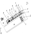
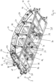
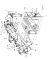
- a second embodiment of the formwork 10 according to the invention is shown in the Fig. 11 to 15 shown.
- the formwork 10 has an interior space 17 for accommodating reinforcement, built-in components, and concrete for producing the concrete segment 500.
- This space is formed by a base 16 and the inner sides of the side walls 14 and the end walls 15.
- the base 16 is arranged on a base 12.
- the side walls 14 and the end walls 15 are fixedly pivotably mounted on the base via a pivot connection 13, 26.
- the pivot connection 13, 26 is connected to the side wall 14 and the end wall 15, respectively, via a connecting element 27.
- the connecting elements 27 Via the connecting elements 27, the side walls 14 and end walls 15 are pivoted about a pivot point 28, so that the side walls 14 and end walls 15 detach from the base 16 and are pivoted outwards, as shown in Figure 13 is shown.
- the pivoting occurs in the direction of the double arrow I.
- the base 12 has a lower frame 28, on which, among other things, a chassis is arranged, which here, for example, has wheels 29.
- the frame 28 can also be arranged on a transport element 112 in order to be moved along a production line, or the travel path of the production line itself has rollers on which the formwork 10 can be moved.
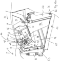
- base elements 31 and actuators 32 here preferably in the form of hydraulic cylinders, which are firmly connected to the base element 31.
- a movement element 33 of the actuator 32 here for example a piston rod, is connected to the connecting element 27.
- the connecting element 27 is moved by a side wall 34 of the base 12 in the direction of the double arrow H.
- it is rotated about the pivot point 38, so that the side wall 14 is moved away from the interior space 17 or floor 16, so that the formwork 10 is opened with respect to the side walls 14.
- At least one actuator 35 is provided to open the end walls 15, which are also connected to the base 12 via a connecting element 27 with a pivot connection 26 having a pivot point 38.
- This actuator can be arranged in the interior 30 in a similar way to the previously described actuator 32 in connection with the base element 31.
- the actuator 35 is arranged on the side wall 14 via a connection 36.
- the actuator 35 is rotatable about a first axis 37 and simultaneously rotatable about a second axis 39, so that when the end wall 15 is open, the actuator 35 can be pivoted together with the side wall 14 when the same is opened.
- connection 40 with which the actuator 35 is connected to the end wall 15.
- the actuator 35 has a movement element 41, here, for example, a piston rod, which can be moved out of the actuator 35 in the double-arrow direction H in order to pivot the end wall 15 about the pivot point 38 in the pivot connection 26 in the double-arrow direction I.
- a corner 46 of the interior space 17 is formed by the contact of an outer side 42 of an end wall 15 with an outer side 43 of a side wall 14.
- a male and a female engagement element 44, 45 are provided on the outer side 42 of the end wall 15 and, correspondingly, on the outer side 43 of the side wall 14, which engage with each other when the formwork is closed.
- the male engagement element 45 is preferably arranged on the end wall 15 and the female engagement element 44 on the side wall 14, such that the male engagement element 45 prevents movement of the side wall 14 when the end wall 15 is closed.
- the end wall 15 is pressed at its outer end 42 onto the side wall 14 at its outer end 43.
- the male engagement element 45 engages the female engagement element 44 and thereby locks, in addition to attracting and holding the movement element 33 of the actuator 32, so that the side wall 14 cannot be detached from the base 16 as long as the end wall 15 rests against the base 16.
- the formwork 10 has two covers 50 which are attached to the base 12 and which, during the manufacturing process of the concrete segment 500, are either closed, as in Figure 11 shown, or opened, as in Figure 13 and 14 shown.
- the covers 50 can be pivoted in the direction of the double arrow J between the closed position on the interior space 17 and the open position. They serve to close the formwork 10 or its interior space 17 upwards when the concrete is poured into the interior space 17.
- formwork 10 is known with partial covers, such as the covers 50 shown here in the second embodiment of the formwork 10 according to the invention, or even without a cover 50, as is the case, for example, in the first embodiment according to the invention.
- the uncovered areas are closed with a cover before the formwork 10 is filled with concrete, leaving open areas through which the concrete is then poured into the interior space 17.
- These additional covers are attached before or in the concreting work station.
- covers 50 are provided on the formwork 10 that can be moved between an open and a closed position, they are closed in or before the concreting work station. After concreting, the covers are either removed or opened again in order to process the surface 520 of the raw concrete segment in a corresponding further work station/in a further work step. After this work step is completed, the covers 50 are closed again.
- the formwork 10 is then fed to the hardening station with the covers 50 closed. Within the hardening station, the covers 50 then remain closed accordingly. After hardening is complete, the covers 50 are opened. Subsequently, the side walls 14 and the end walls 15 are also opened in the necessary sequence.
- the pre-hardened concrete segment 500 can then be removed.
- the formwork 10 is cleaned accordingly and prepared for the production of a new concrete segment 500, as previously described.
- the side walls 14, end walls 15, and cover 50 are either closed or remain open.
- the covers 50, end walls 15, and side walls 14 may then need to be reopened to allow for complete cleaning.
- the side walls 14 and end walls 15 are closed.
- the interior space 17 is then fitted with the appropriate reinforcement and built-in components.
- the lids 50 are provided with connecting elements 51, which are connected to the base 12 via a pivot connection 52.
- the pivot connection 52 is rotatably arranged on a projection element 53.
- An actuator 54 is provided, which is connected to the base 12 parallel to the projection element 53.
- the connecting element 51 extends beyond the pivot connection 52.
- the movement element 55 of the actuator 54 then engages this part of the connecting element 51.
- spring elements 56 are provided for support.
- the actuator 54 is preferably a hydraulic cylinder.
- the moving element 55 represents the piston rod of the hydraulic cylinder.
- the actuator 54 also holds the cover 50 in the respective position.
- securing elements 57 are provided on the cover 50 for securing the lid. These securing elements are equipped with an actuator 58 having a movement element 59.
- the movement element 59 is connected to a locking element 60, which can be moved, preferably pivoted, between a locking position and a free position by extending and retracting the movement element 59.
- engagement openings 61 are provided for locking, into which the locking element 60 engages for locking. Locking occurs, for example, during curing.
- the actuators of formwork 10 are part of a hydraulic circuit.
- the actuators are referred to below as hydraulic cylinders.
- the hydraulic cylinders 32 for opening and closing the side walls and the hydraulic cylinders 35 for opening and closing the end walls are provided such that the walls close when the hydraulic cylinder retracts.
- the hydraulic cylinders 54 of the cover 50 and the hydraulic cylinders 58 for actuating the locking elements 60 are arranged such that the cover 50 and the locking element 60 close when the hydraulic cylinder retracts.
- the hydraulic circuit is connected to a hydraulic unit (not shown) via a connection.
- a hydraulic unit not shown
- the application of the holding force of the hydraulic cylinders after closing the side walls 14 and end walls 15, as well as after closing the covers 50 and the locking elements 60, must remain in place even after the hydraulic circuit of the formwork 10 is disconnected from the drive unit.
- load-holding valves (not shown) integrated into the hydraulic circuit. These valves prevent the hydraulic fluid introduced into the hydraulic cylinder from flowing back out once the hydraulic unit no longer supplies the hydraulic circuit with hydraulic fluid, thus maintaining a constant pressure on the piston surface of the hydraulic cylinder.
- compensation elements are provided at appropriate points in the hydraulic circuit. These can be, for example, diaphragm accumulators or dummy cylinders.
- the cylinders that are first supplied with hydraulic fluid determine the necessary control sequence. Between the individual cylinders, the sequence of control of the Switchable locking elements for individual movements can be provided. These are preferably pressure sequence valves.
Landscapes
- Engineering & Computer Science (AREA)
- Mechanical Engineering (AREA)
- Chemical & Material Sciences (AREA)
- Ceramic Engineering (AREA)
- Manufacturing & Machinery (AREA)
- Structural Engineering (AREA)
- Robotics (AREA)
- Architecture (AREA)
- Mining & Mineral Resources (AREA)
- Automation & Control Theory (AREA)
- Civil Engineering (AREA)
- General Life Sciences & Earth Sciences (AREA)
- Geochemistry & Mineralogy (AREA)
- Geology (AREA)
- Life Sciences & Earth Sciences (AREA)
- Lining And Supports For Tunnels (AREA)
- Moulds, Cores, Or Mandrels (AREA)
- Devices For Post-Treatments, Processing, Supply, Discharge, And Other Processes (AREA)
- On-Site Construction Work That Accompanies The Preparation And Application Of Concrete (AREA)
Applications Claiming Priority (3)
| Application Number | Priority Date | Filing Date | Title |
|---|---|---|---|
| DE102019109084 | 2019-04-07 | ||
| EP20721159.0A EP3953122B1 (fr) | 2019-04-07 | 2020-04-07 | Installation de production et procédé de fabrication d'un cuvelage en béton d'un système de construction de tunnels |
| PCT/EP2020/059943 WO2020208046A2 (fr) | 2019-04-07 | 2020-04-07 | Installation de production et procédé de fabrication d'un cuvelage en béton d'un système de soutènement de tunnel |
Related Parent Applications (1)
| Application Number | Title | Priority Date | Filing Date |
|---|---|---|---|
| EP20721159.0A Division EP3953122B1 (fr) | 2019-04-07 | 2020-04-07 | Installation de production et procédé de fabrication d'un cuvelage en béton d'un système de construction de tunnels |
Publications (2)
| Publication Number | Publication Date |
|---|---|
| EP4520498A2 true EP4520498A2 (fr) | 2025-03-12 |
| EP4520498A3 EP4520498A3 (fr) | 2025-05-07 |
Family
ID=67220630
Family Applications (6)
| Application Number | Title | Priority Date | Filing Date |
|---|---|---|---|
| EP19182281.6A Withdrawn EP3722058A1 (fr) | 2019-04-07 | 2019-06-25 | Installation de production et procédé de fabrication d'un cuvelage en béton d'un système de construction de tunnels |
| EP20721158.2A Active EP3953121B1 (fr) | 2019-04-07 | 2020-04-07 | Coffrage servant à la fabrication d'un segment de cuvelage en béton d'un système d'aménagement pour tunnel |
| EP25154557.0A Pending EP4520498A3 (fr) | 2019-04-07 | 2020-04-07 | Coffrage servant à la fabrication d'un segment de cuvelage en béton d'un système d'aménagement pour tunnel |
| EP24176651.8A Pending EP4397455A3 (fr) | 2019-04-07 | 2020-04-07 | Installation de production et procédé de fabrication d'un cuvelage en béton d'un système de soutènement de tunnel |
| EP20721159.0A Active EP3953122B1 (fr) | 2019-04-07 | 2020-04-07 | Installation de production et procédé de fabrication d'un cuvelage en béton d'un système de construction de tunnels |
| EP21167296.9A Withdrawn EP3892429A1 (fr) | 2019-04-07 | 2021-04-07 | Installation de durcissement permettant de durcir un cuvelage de béton dans un système de construction de tunnel |
Family Applications Before (2)
| Application Number | Title | Priority Date | Filing Date |
|---|---|---|---|
| EP19182281.6A Withdrawn EP3722058A1 (fr) | 2019-04-07 | 2019-06-25 | Installation de production et procédé de fabrication d'un cuvelage en béton d'un système de construction de tunnels |
| EP20721158.2A Active EP3953121B1 (fr) | 2019-04-07 | 2020-04-07 | Coffrage servant à la fabrication d'un segment de cuvelage en béton d'un système d'aménagement pour tunnel |
Family Applications After (3)
| Application Number | Title | Priority Date | Filing Date |
|---|---|---|---|
| EP24176651.8A Pending EP4397455A3 (fr) | 2019-04-07 | 2020-04-07 | Installation de production et procédé de fabrication d'un cuvelage en béton d'un système de soutènement de tunnel |
| EP20721159.0A Active EP3953122B1 (fr) | 2019-04-07 | 2020-04-07 | Installation de production et procédé de fabrication d'un cuvelage en béton d'un système de construction de tunnels |
| EP21167296.9A Withdrawn EP3892429A1 (fr) | 2019-04-07 | 2021-04-07 | Installation de durcissement permettant de durcir un cuvelage de béton dans un système de construction de tunnel |
Country Status (12)
| Country | Link |
|---|---|
| US (2) | US20220250277A1 (fr) |
| EP (6) | EP3722058A1 (fr) |
| AU (2) | AU2020271386A1 (fr) |
| CA (2) | CA3134788A1 (fr) |
| ES (2) | ES3015142T3 (fr) |
| HR (2) | HRP20250321T1 (fr) |
| HU (2) | HUE071056T2 (fr) |
| IL (2) | IL287000B1 (fr) |
| PL (2) | PL3953122T3 (fr) |
| RS (2) | RS65995B1 (fr) |
| SG (2) | SG11202111146SA (fr) |
| WO (2) | WO2020208046A2 (fr) |
Families Citing this family (10)
| Publication number | Priority date | Publication date | Assignee | Title |
|---|---|---|---|---|
| CN112278760B (zh) * | 2020-11-06 | 2022-04-01 | 广东博智林机器人有限公司 | 预制构件转运系统及转运方法 |
| CN112523778B (zh) * | 2020-12-02 | 2023-06-16 | 广东磐龙交通环境设施工程有限公司 | 一种轨道交通管片预埋连接套筒 |
| CN113021610A (zh) * | 2021-03-12 | 2021-06-25 | 修武县奥德隆科技有限责任公司 | 用于超低能耗房屋装配墙板的智能化生产线 |
| CN113681704A (zh) * | 2021-08-26 | 2021-11-23 | 成都锐龙机械制造有限公司 | 一种梁的预制装置及其应用的控制系统 |
| IT202100029252A1 (it) * | 2021-11-18 | 2023-05-18 | Fama Srl | Cassaforma e procedimento per la produzione di conci gettati |
| CN115008594B (zh) * | 2022-06-22 | 2024-02-06 | 一鸣建设集团有限公司 | 一种建筑隔墙板流水线生产系统 |
| CN115614063B (zh) * | 2022-11-23 | 2023-09-29 | 中国安能集团第三工程局有限公司 | 一种隧道二次衬砌模板台车 |
| DE102023124388A1 (de) * | 2023-09-11 | 2025-03-13 | FUCHS Europoles Wind GmbH | Konisches oder zylindrisches Ringsegment, Spannbetonturm und Verfahren zur Herstellung eines Ringsegments |
| CN116968164B (zh) * | 2023-09-12 | 2024-02-06 | 江苏丰和隧道设备有限公司 | 一种智能化的盾构管片蒸养出库控制方法及系统 |
| EP4621166A1 (fr) | 2024-03-19 | 2025-09-24 | Siemens Gamesa Renewable Energy Innovation & Technology, S.L. | Procédé de fabrication d'une tour, tour et moule de coulée |
Family Cites Families (33)
| Publication number | Priority date | Publication date | Assignee | Title |
|---|---|---|---|---|
| DE1887648U (de) * | 1962-01-20 | 1965-02-10 | Bauunternehmung Lorenz Resting, Hoch-Tief-Stahlbeton und Industriebau, Lünen-Brambauer | Vorgefertigte reihbare Zelle zum Beschleunigen des Abbindens von Betonfertigteilen |
| SE318510B (fr) * | 1966-12-17 | 1969-12-08 | W Schneider | |
| JPS5263216A (en) * | 1975-11-20 | 1977-05-25 | P S Concrete | Mold for production of concrete segment |
| JPS54152027A (en) * | 1978-05-22 | 1979-11-29 | Agency Of Ind Science & Technol | Separation and purification of chlorophyll |
| JPS5751864Y2 (fr) * | 1978-07-22 | 1982-11-11 | ||
| JPS5794103A (en) * | 1980-12-03 | 1982-06-11 | Daikin Ind Ltd | Hydraulic circuit |
| GB2127343B (en) * | 1982-09-03 | 1986-07-30 | Myrayarn Limited | Improvements in or relating to methods of casting concrete articles |
| JPH0354127Y2 (fr) * | 1984-09-20 | 1991-11-28 | ||
| FR2581923B1 (fr) * | 1985-02-20 | 1988-04-08 | Alskanor Const Maisons Ind | Moule ouvrant pour obtention de pieces notamment en beton |
| JPH04189506A (ja) * | 1990-11-26 | 1992-07-08 | Nippon Pressed Concrete Co Ltd | コンクリートセグメント製作用型枠 |
| DE19511744C2 (de) * | 1995-03-30 | 1997-08-14 | Ytong Ag | Vorrichtung zur Betätigung von Verriegelungseinrichtungen an einer Schalungsform für Beton, insbesondere für Gasbeton |
| JPH08277898A (ja) * | 1995-04-05 | 1996-10-22 | Takeshi Yanagisawa | ロボット装置 |
| JP2001047421A (ja) * | 1999-08-11 | 2001-02-20 | Fujimi Koken Kk | 型枠装置 |
| WO2004065086A2 (fr) * | 2003-01-20 | 2004-08-05 | Roland Weber | Usine de chantier mobile, compacte et flexible |
| DE102005042179B4 (de) * | 2005-09-06 | 2010-07-08 | Thyssenkrupp Drauz Nothelfer Gmbh | Flexible Fertigungszelle für die Bearbeitung von Bauteilen, insbesondere von Fahrzeugkarosserien |
| DE202006016561U1 (de) * | 2006-10-30 | 2007-03-08 | Kastner, Erich | Vorrichtung zum Herstellen von Fertigteilen aus aushärtbarer Gießmasse |
| DE102007032236B4 (de) * | 2007-07-11 | 2009-04-16 | Rekers Betonwerk Gmbh & Co. Kg | Schalung zur Herstellung von Betonfertigteilen |
| WO2010089114A1 (fr) * | 2009-02-04 | 2010-08-12 | Sms Siemag Ag | Dispositif d'agrandissement de la zone de travail |
| CN101486229A (zh) * | 2009-02-10 | 2009-07-22 | 江苏工业学院 | 隧道混凝土管片钢模液压驱动铰链开合装置 |
| DE102009051583A1 (de) * | 2009-10-21 | 2011-04-28 | IPR-Intelligente Peripherien für Roboter GmbH | Robotersystem und Verfahren zum Verlegen eines Schienenstrangs |
| DE102012010664A1 (de) * | 2012-05-31 | 2012-12-13 | Daimler Ag | Produktionsanlage mit einer Mehrzahl von Arbeitsstationen und Verfahren zum Betreiben einer solchen Produktionsanlage |
| NZ713015A (en) * | 2013-03-14 | 2020-03-27 | Solidia Technologies Inc | Curing systems for materials that consume carbon dioxide |
| CN103726857B (zh) * | 2013-11-28 | 2017-01-04 | 江苏牧羊控股有限公司 | 一种盾构管片柔性模具 |
| CN105082346B (zh) * | 2015-02-09 | 2019-02-19 | 中交第三航务工程局有限公司 | 一种盾构管片预制智能流水生产线 |
| CN206158755U (zh) * | 2016-11-16 | 2017-05-10 | 中铁工程装备集团机电工程有限公司 | 一种盾构管片生产模具 |
| MX2017009909A (es) * | 2017-07-31 | 2019-02-08 | German Becerril Hernandez | Sistema automatizado de construccion robotizado y metodo de construccion. |
| CN207359319U (zh) * | 2017-10-31 | 2018-05-15 | 中建七局第四建筑有限公司 | 一种移动光伏智能一体化标养室 |
| CN207495750U (zh) * | 2017-11-20 | 2018-06-15 | 上海隧道工程有限公司构件分公司 | 用于水泥管片圆弧面自动收水抹平系统的龙门架运动装置 |
| CN107901208A (zh) * | 2017-12-07 | 2018-04-13 | 郑州市第建筑工程集团有限公司 | 预制钢筋混凝土管片全自动生产线 |
| CN107932697A (zh) * | 2017-12-15 | 2018-04-20 | 周兆弟 | 一种合模螺栓 |
| CN208359048U (zh) * | 2018-06-07 | 2019-01-11 | 中国水利水电夹江水工机械有限公司 | 一种管片水养搬运系统 |
| CN109159273A (zh) * | 2018-10-24 | 2019-01-08 | 中建科技有限公司 | 地下综合预制管廊混凝土预制构件的自动化生产方法 |
| CN109227899A (zh) * | 2018-11-21 | 2019-01-18 | 扬州牧羊隧道设备有限公司 | 一种新型隧道衬砌管片模具 |
-
2019
- 2019-06-25 EP EP19182281.6A patent/EP3722058A1/fr not_active Withdrawn
-
2020
- 2020-04-07 HU HUE20721159A patent/HUE071056T2/hu unknown
- 2020-04-07 ES ES20721159T patent/ES3015142T3/es active Active
- 2020-04-07 CA CA3134788A patent/CA3134788A1/fr active Pending
- 2020-04-07 EP EP20721158.2A patent/EP3953121B1/fr active Active
- 2020-04-07 RS RS20241013A patent/RS65995B1/sr unknown
- 2020-04-07 SG SG11202111146SA patent/SG11202111146SA/en unknown
- 2020-04-07 EP EP25154557.0A patent/EP4520498A3/fr active Pending
- 2020-04-07 ES ES20721158T patent/ES2988348T3/es active Active
- 2020-04-07 WO PCT/EP2020/059943 patent/WO2020208046A2/fr not_active Ceased
- 2020-04-07 EP EP24176651.8A patent/EP4397455A3/fr active Pending
- 2020-04-07 AU AU2020271386A patent/AU2020271386A1/en not_active Abandoned
- 2020-04-07 EP EP20721159.0A patent/EP3953122B1/fr active Active
- 2020-04-07 PL PL20721159.0T patent/PL3953122T3/pl unknown
- 2020-04-07 HR HRP20250321TT patent/HRP20250321T1/hr unknown
- 2020-04-07 RS RS20250264A patent/RS66664B1/sr unknown
- 2020-04-07 PL PL20721158.2T patent/PL3953121T3/pl unknown
- 2020-04-07 HR HRP20241259TT patent/HRP20241259T1/hr unknown
- 2020-04-07 US US17/599,075 patent/US20220250277A1/en not_active Abandoned
- 2020-04-07 AU AU2020271618A patent/AU2020271618A1/en not_active Abandoned
- 2020-04-07 SG SG11202111147TA patent/SG11202111147TA/en unknown
- 2020-04-07 WO PCT/EP2020/059870 patent/WO2020208006A2/fr not_active Ceased
- 2020-04-07 CA CA3134789A patent/CA3134789A1/fr active Pending
- 2020-04-07 IL IL287000A patent/IL287000B1/en unknown
- 2020-04-07 HU HUE20721158A patent/HUE068257T2/hu unknown
-
2021
- 2021-04-07 US US17/599,732 patent/US20220168921A1/en not_active Abandoned
- 2021-04-07 EP EP21167296.9A patent/EP3892429A1/fr not_active Withdrawn
- 2021-10-05 IL IL287001A patent/IL287001A/en unknown
Also Published As
Similar Documents
| Publication | Publication Date | Title |
|---|---|---|
| EP3953121B1 (fr) | Coffrage servant à la fabrication d'un segment de cuvelage en béton d'un système d'aménagement pour tunnel | |
| DE102020111413A1 (de) | Schnellverbindungssystem | |
| WO2005037553A1 (fr) | Elements structurels mobiles dans une machine d'impression | |
| WO1984004127A1 (fr) | Echafaudage a progression par moteur pour batiments, tendeur de cable, et procede pour construire et/ou entretenir des batiments de grande hauteur | |
| EP4200479A1 (fr) | Unité à changement rapide et système à changement rapide | |
| DE2323267A1 (de) | Vorrichtung zum aufbringen einer verbindungsmuffe auf zwei stangen, insbesondere bewehrungsstaehle | |
| DE10139807B4 (de) | Manipulationsvorrichtung | |
| EP1261465A1 (fr) | Surmoule | |
| EP0348870B1 (fr) | Construction constituée par l'assemblage d'éléments préfabriqués en béton armé utilisant la technique du béton précontraint | |
| EP1673223A1 (fr) | Unites d'impression et procede de deplacement d'un element structurel | |
| DE102021117304A1 (de) | Schachteckenschalung | |
| DE202021102613U1 (de) | Pressring, Presswerkzeug und Adapterelemente | |
| DE202014104553U1 (de) | Schnellwechselvorrichtung für ein Baugerät mit Ausleger | |
| DE102020122839A1 (de) | Schaltbare Magnetvorrichtung | |
| DE2132021A1 (de) | Vorrichtung,vorzugsweise Richtvorrichtung zum Ausfuehren der Operationen fuer das Ausbessern und Zurueckverformen bzw.Zurueckfuehren auf die urspruengliche Form von z.B.verbeulten oder beschaedigten Blechen von Karosserien,insbesondere von Kraftfahrzeugen | |
| DE4122567C2 (fr) | ||
| DE102018212422A1 (de) | Magnetische Schalungsvorrichtung | |
| DE19628608A1 (de) | Extrusionskopf mit Schließzylindern | |
| EP1964808A2 (fr) | Plaque d'appui | |
| EP3318384B1 (fr) | Porte-outil et installation de fabrication avec un tel porte-outil | |
| DE69009192T2 (de) | Pfeileraufbau. | |
| DE69608379T2 (de) | Verfahren zum Verbinden eines Abzweigrohrs an eine Hauptleitung | |
| DE60016464T2 (de) | Werkzeugzusammenbau | |
| EP1587659A1 (fr) | Dispositif pour distribuer de la matiere plastique en fusion dans un moule de coulage par injection avec plusieurs etages | |
| DE3739221A1 (de) | Strebausbau |
Legal Events
| Date | Code | Title | Description |
|---|---|---|---|
| PUAI | Public reference made under article 153(3) epc to a published international application that has entered the european phase |
Free format text: ORIGINAL CODE: 0009012 |
|
| STAA | Information on the status of an ep patent application or granted ep patent |
Free format text: STATUS: THE APPLICATION HAS BEEN PUBLISHED |
|
| AC | Divisional application: reference to earlier application |
Ref document number: 3953122 Country of ref document: EP Kind code of ref document: P |
|
| AK | Designated contracting states |
Kind code of ref document: A2 Designated state(s): AL AT BE BG CH CY CZ DE DK EE ES FI FR GB GR HR HU IE IS IT LI LT LU LV MC MK MT NL NO PL PT RO RS SE SI SK SM TR |
|
| REG | Reference to a national code |
Ref country code: DE Ref legal event code: R079 Free format text: PREVIOUS MAIN CLASS: B28B0011240000 Ipc: B28B0005040000 |
|
| PUAL | Search report despatched |
Free format text: ORIGINAL CODE: 0009013 |
|
| AK | Designated contracting states |
Kind code of ref document: A3 Designated state(s): AL AT BE BG CH CY CZ DE DK EE ES FI FR GB GR HR HU IE IS IT LI LT LU LV MC MK MT NL NO PL PT RO RS SE SI SK SM TR |
|
| RIC1 | Information provided on ipc code assigned before grant |
Ipc: B28B 11/24 20060101ALI20250402BHEP Ipc: B25J 11/00 20060101ALI20250402BHEP Ipc: E21D 11/08 20060101ALI20250402BHEP Ipc: B28B 7/00 20060101ALI20250402BHEP Ipc: B25J 5/04 20060101ALI20250402BHEP Ipc: B28B 17/00 20060101ALI20250402BHEP Ipc: B28B 15/00 20060101ALI20250402BHEP Ipc: B28B 5/04 20060101AFI20250402BHEP |
|
| STAA | Information on the status of an ep patent application or granted ep patent |
Free format text: STATUS: REQUEST FOR EXAMINATION WAS MADE |
|
| 17P | Request for examination filed |
Effective date: 20251104 |