EP4527471A1 - Dispositif de décharge de pression d'explosion sans flamme - Google Patents
Dispositif de décharge de pression d'explosion sans flamme Download PDFInfo
- Publication number
- EP4527471A1 EP4527471A1 EP23198348.7A EP23198348A EP4527471A1 EP 4527471 A1 EP4527471 A1 EP 4527471A1 EP 23198348 A EP23198348 A EP 23198348A EP 4527471 A1 EP4527471 A1 EP 4527471A1
- Authority
- EP
- European Patent Office
- Prior art keywords
- filter mats
- strip
- filter
- composite
- mats
- Prior art date
- Legal status (The legal status is an assumption and is not a legal conclusion. Google has not performed a legal analysis and makes no representation as to the accuracy of the status listed.)
- Pending
Links
Images




Classifications
-
- A—HUMAN NECESSITIES
- A62—LIFE-SAVING; FIRE-FIGHTING
- A62C—FIRE-FIGHTING
- A62C4/00—Flame traps allowing passage of gas but not of flame or explosion wave
Definitions
- a device for flameless explosion venting is currently being marketed by the applicant under the name Q-Box II.
- the Q-Box II is reliable and has proven itself over many years of use.
- the Q-Box II has a welded frame formed by the side walls and the connecting parts, which are joined together by welding.
- the side walls are roughly in the shape of a quarter circle.
- the Q-Box as a whole is therefore roughly in the shape of a right cylinder with the base area of a quarter circle.
- This cylinder has a curved side formed by the outer bars, the outer round arches, and filter mats.
- the rear of the Q-Box is closed by a wall that connects to the filter mats and the side walls.
- the last side of the Q-Box is closed by an explosion venting device, usually a rectangular bursting disc.
- the Q-Box can be connected to a container or a line. If an explosion occurs in the container or pipe, the explosion venting device opens due to the pressure increase, allowing the hot, possibly burning gases inside the container or pipe to flow through the opened explosion venting device into the interior of the Q-Box. From there, the gases can escape through the filter mats into the surrounding atmosphere. This cools the gases and extinguishes the flames, so that little or no hot gas or flames can escape from the Q-Box.
- the inventors were given the task of proposing a new device for flameless explosion venting based on the Q-Box II, which would require less space during shipping compared to the Q-Box II.
- the device according to the invention for flameless explosion pressure relief comprises an inventive composite of filter mats.
- This inventive composite of filter mats comprises several filter mats. Each filter mat has a first end and a second end, which are opposite one another. The first ends of the filter mats are connected to one another. The ends of the filter mats can be connected to one another directly or indirectly, for example via connecting means. Direct connection is possible by gluing or sewing or the like.
- the filter mats can be layers of knitted fabrics, woven fabrics, and nonwovens. The knitted fabrics, woven fabrics, and nonwovens can be made of metallic threads or wires.
- the connecting means can not only have the function of connecting the ends of the filter mats to each other, but also of connecting the assembly to the connecting parts of the device.
- the connecting means can each have at least one connecting structure for connecting to the connecting parts of the device for flameless pressure relief.
- the assembly can thus be used as a unit over the Connecting structures of the connecting means are connected to the remaining device for flameless pressure relief.
- the connecting structures can be suitable and configured for a detachable connection between the assembly and the connecting parts. This makes it possible to replace the assembly with filter mats of a flameless pressure relief device.
- the connecting means of a composite according to the invention can comprise sleeves as connecting structures through which, for example, screws for fastening the connecting means to the connecting parts can be inserted or through which screws are inserted.
- a composite according to the invention can have two receptacles as connecting means.
- the first ends of the filter mats or of the part of the filter mats can be accommodated in a first of the two receptacles.
- the second ends of the filter mats or of the part of the filter mats can then preferably be accommodated in a second of the two receptacles.
- the receptacles can have a first bar and a second bar, between which the ends of the filter mats or part of the filter mats are arranged.
- the filter mats can be held between these two bars and by these two bars in a force-fitting manner.
- the ends of the filter mats or part of the filter mats can be held by a form-fitting arrangement between the two bars.
- the receptacle can have holding elements. These can be attached to one of the bars or to both bars of each receptacle.
- the sleeves can form such holding elements.
- the sleeves can connect the first bar and the second bar.
- the filter mats or the filter mats of the part of the filter mats can have through holes at the first end and at the second end through which the sleeve passes. This connects the filter mats to one another by a positive fit.
- first end and the second end of a filter mat of the filter mats or of a part of the filter mats that are not accommodated in one of the receptacles to be attached to a first bar of the bars of each receptacle.
- the first strip of each receptacle can have a strip, and a fold can be provided at each of the first and second ends of the filter mat or part of the filter mats. These folds can be wrapped around one of the strips each.
- the first end or the second end of the filter mat or of the filter mats and the receptacle can have through-holes that form connecting elements for attaching the assembly to the connecting means.
- the through-holes of the receptacles can in particular be provided in the strip around which the fold is wrapped. Rivets can be inserted into the through-holes.
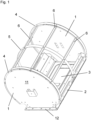
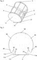
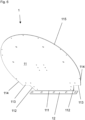
- the device V according to the invention shown in the figures has identical side walls 1 with side surfaces 11, with an edge of an arcuate section 115 and with a first straight section 111 opposite the side wall 1 is mirror-symmetrical to a plane perpendicular to the side surface which contains the perpendicular bisector of the first straight section 111.
- the arcuate portion 115 of the edge of the side surfaces 11 is a circular arc.
- the circular arc extends over an angular range of 230° from one end to the other.
- the edge has a second straight section 112 that forms a tangent to the end of the arcuate section.
- These second straight sections 112 are each followed by a third straight section 113 that is parallel to the first straight section 111 and extends inward from the second straight section 112.
- a fourth straight section 114 begins, parallel to the second straight section 112, and adjoins one of the ends of the first straight section 111.
- the first straight section 111 and the fourth straight section 114 form an angle of approximately 115°.
- the first straight section 111 is followed by a flange area 12 angled outwards by approximately 90° relative to the side surface 11.
- the identical connecting parts 2 each have a flange area 21, which, together with the flange area 12 of the side walls 1, forms a flange 12, 21 with which the flameless pressure relief device can be attached to another object.
- This can be, for example, a container or a pipeline.
- a rupture disc 6 of the device is arranged between the other object and the flange 12, 21.
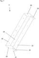
- the connecting parts 2 have a first connecting strip 22 connected to the flange area 21 and angled upwards at an angle of approximately 65° relative to the flange.
- the first connecting strip 22 follows the fourth straight section 114 at the edge of the side surface 11 of the side wall 1, which then also determines the orientation of the first connecting strip 22.
- the height of the connecting strip 22 corresponds to the length of the fourth straight section 114 of the edge of the side surface 11.
- Tabs 23 are provided at the ends of the first connecting strip 22. These are angled by approximately 90° relative to the first connecting strip 23 and are fastened to the first and second side walls 1, respectively. For this purpose, through holes are provided in the tabs 23, with which through holes in the side wall 1 are aligned.
- the connecting parts 2 and the side walls 1 are connected by rivets 81, which are set in these through holes. In a device according to the invention, a different type of connection between the side walls 1 and the side walls could also be selected.
- the connecting parts 2 each have a web 24. This connects to the first connecting strip 22. This preferably lies in a plane parallel to the flange area 21 and follows the edge of the side surface 11 in the area of the third straight section 113. It is as deep as the third straight section 113 of the edge of the side surface 11 is long.
- the depth of the web 24 corresponds to the thickness of a filter mat or a composite of filter mats which is or are Figures 1 to 9a are not shown.
- the connecting parts 2 each have a second connecting strip 25.
- This second connecting strip 25 is arranged in a plane parallel to the first connecting strip 22 and adjoins the web 24. Furthermore, the second Connecting strip 25 the edge of the side surface 11 in the region of the second straight section 112. It is approximately as high as the second straight section 112 is long.
- Tabs 26 can be provided at the ends of the second connecting strip 25. These are angled by approximately 90° with respect to the second connecting strip and rest against the first and second side walls 1, respectively. Through holes are provided in the tabs 26, with which through holes in the side wall are aligned.
- the connecting parts and the side walls are connected by rivets 82, which are placed in these through holes. In a device according to the invention, a different type of connection between the side walls 1 and the side walls could also be selected.
- the orientation of the first connecting strip 22 is selected such that an opening rupture disc 3 opens with the maximum possible opening angle in the interior of the device without first striking the first connecting strip 22.
- the maximum possible opening angle in the device according to the invention is determined by the pivot radius of the opening part of the rupture disc 3 and by where this opening part strikes the inside of the filter mat or the assembly with filter mats.
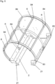
- Round arches of the device according to the invention can be designed in various ways. For example, there can be two first outer round arches 4. Each of these round arches 4 can rest against an inner side of one of the side walls 1 or overlap one of the side walls 1.
- Ends of the first outer round arches 4 are connected to the connecting parts 2, in particular to the first second connecting strips 25.
- the ends of the outer round arches 4 and the second connecting strips 25 have aligned through holes into which rivets 83 are inserted.
- the first outer arches 4 can be connected to the ends of outer bars 6. For this purpose, aligned through holes are provided at the ends of the outer bars 6 and in the first outer arches 4, into which rivets 84 are inserted.
- the first outer arches 4 may have a U-shaped cross-section.
- the legs of the first outer arches 4, which are U-shaped in cross-section, are directed inward and rest against the filter mat or the composite of filter mats.
- each first outer round arch 4 which is U-shaped in cross-section and which rests against the side wall 1
- through holes are provided which are aligned with through holes in the side walls. Rivets 85 are inserted into these through holes.
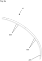
- Slots 411 can be provided on both sides of the through holes in the legs 41 of each first outer round arch 4 resting against the side wall 1, as shown in the Fig. 8a These slots prevent the previously created through holes from deforming due to the applied bending forces when the sheet is bent.
- the first outer round arches 4 can have recesses at connection points or in a region of the connection points with outer bars 6, into which the respective outer bar 6 engages, which is connected at these connection points to the first outer round arch 4 and the side walls 1.
- the outer round arches also include a second outer round arch 5. This is arranged between the first outer round arches 4.
- the second outer round arch 5 can have a cross-section of have a rectangular profile.
- a device according to the invention may also have no second outer round arch or several second outer round arches.
- the second outer arch 5 can cross the outer bars 6.
- the outer bars 6 have slots at these intersections.
- the second outer arch 5 is inserted through these slots.
- aligned through holes can be provided in the outer bars 6 and in the second outer arch, into which rivets 86 are inserted.
- Ends of the second outer arch 5 are connected to the connecting parts 2, in particular to the first second connecting strips 25.
- the ends of the second outer arch 5 and the second connecting strips 25 have aligned through holes into which rivets 87 are inserted.
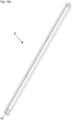
- the outer bars 6 are bars with a U-profile ( Fig. 10 ) or hat profile ( Fig. 10a ) as a cross-sectional profile.
- Tabs 61 are provided at the ends of the outer bars 6. These tabs 61 are angled relative to the remaining outer bars and are connected to one of the side walls 1. For this purpose, aligned through holes are provided in the tabs 61 and the side walls 1, into which rivets 87 are inserted.
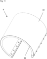
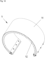
- a device according to the invention can comprise a composite 9 of filter mats ( Fig. 11 to 14 ).
- the composite 9 comprises a first outer filter mat 91 and several inner filter mats 92.
- the inner filter mats 92 are placed on top of one another and are shown in the figures as a compact block of inner filter mats 92.
- the ends of the inner filter mats 92 are each enclosed in a receptacle 93, 94, 95.
- Each of these receptacles has a first strip 93, a second strip 94, and several sleeves 95.
- the first strip 93 has three strips 931, 932, 933.
- a first strip 931 of the three strips 931, 932, 933 and a second strip 932 of the three strips 931, 932, 933 are approximately at right angles to one another.
- a third strip 933 is attached to the second strip 932, and the second and third strips 932, 933 form an acute angle of approximately 15 to 30°.
- Through holes are provided along a straight line in the first strip 931 at a distance from the second strip 932.
- Sleeves 95 are attached to the first strip, parallel to the second strip and continuing the through holes in the first strip 931.
- the sleeves have a length approximately equal to the width of the second strip.
- the second strip 94 is attached to the ends of the sleeves 95.
- the second strip 94 has a central strip 941 and two outer strips 942.
- the central strip also has through holes along a straight line and at a distance from the sleeves 95 and the through holes in the first strip 93, which connect to the sleeves 95, so that a channel is formed between the through holes in the first strip 93 and the through holes in the second strip 94, which channel is delimited by the sleeves 95.
- the two outer strips adjoin the middle strip 941 and form an angle of approximately 135° with the middle strip 941.
- An edge of the outer strips 942 opposite the middle strip 941 is serrated, and the resulting serrations engage the inner filter mats 92.
- the inner filter mats 92 also have through-holes at their enclosed ends.
- the sleeves 95 extend through these through-holes in the enclosed ends, which are thereby enclosed between the first strip 93 and the second strip 94 of the receptacle 93, 94, 95.
- the outer filter mat 91 also has through-holes that align with the channels formed, among other things, by the sleeves 95.
- the assembly 9 is screwed to the connecting parts 2 by screws 97, which are guided through the channels and the through-holes in the outer filter mat 91, and cap nuts 98, which are screwed onto the ends of the screws. By tightening the cap nuts 98, the outer filter mat 91 can be pressed against the second bar 94, although this is not shown in the figures.
- the outer filter mat 91 is then connected to the receptacles 93, 94, 95 not only by positive locking, but also by frictional locking.
- the ends of the outer filter mat 91 are pulled over a side of the third strip 933 facing away from the second strip 932 of the first strip 93 and folded, wherein the fold encloses the end of the third strip 933 of the first strip 93.
- the third strips 933 and the ends of the outer filter mat 91 pulled over the third strips 933 rest against the webs 24 of the connecting parts 2 and are fastened to the webs 24 of the connecting parts 2 by means of rivets.
- the assembly 9 of the filter mats 91, 92 forms a unit that can be pre-assembled and only later brought together with the remaining parts of the device according to the invention when the device is fully assembled.
- the assembly 9 like the other parts 1, 2, 3, 4, 5, 6 and the screws, nuts, and rivets connecting these parts, can be transported to a location where assembly takes place.
- a kit containing these parts (1, 2, 3, 4, 5, 6, 9) and the bolts, nuts, and rivets connecting these parts can be assembled at the manufacturing site.
- This kit is then assembled at another location, such as a sales office or on a construction site. This has the advantage that the kits are smaller in volume than the fully assembled devices, saving space during shipping.
- the filter mats 91, 92 can be made from pre-cut pieces of knitted fabric.
- the inner filter mats 92 can have different mesh sizes.
- the mesh size is on average between 1 and 6 mm, preferably 1.2 to 5.5 mm.
Landscapes
- Health & Medical Sciences (AREA)
- Public Health (AREA)
- Business, Economics & Management (AREA)
- Emergency Management (AREA)
- Filtering Materials (AREA)
Priority Applications (1)
| Application Number | Priority Date | Filing Date | Title |
|---|---|---|---|
| EP23198348.7A EP4527471A1 (fr) | 2023-09-19 | 2023-09-19 | Dispositif de décharge de pression d'explosion sans flamme |
Applications Claiming Priority (1)
| Application Number | Priority Date | Filing Date | Title |
|---|---|---|---|
| EP23198348.7A EP4527471A1 (fr) | 2023-09-19 | 2023-09-19 | Dispositif de décharge de pression d'explosion sans flamme |
Publications (1)
| Publication Number | Publication Date |
|---|---|
| EP4527471A1 true EP4527471A1 (fr) | 2025-03-26 |
Family
ID=88097445
Family Applications (1)
| Application Number | Title | Priority Date | Filing Date |
|---|---|---|---|
| EP23198348.7A Pending EP4527471A1 (fr) | 2023-09-19 | 2023-09-19 | Dispositif de décharge de pression d'explosion sans flamme |
Country Status (1)
| Country | Link |
|---|---|
| EP (1) | EP4527471A1 (fr) |
Citations (4)
| Publication number | Priority date | Publication date | Assignee | Title |
|---|---|---|---|---|
| US3711259A (en) * | 1969-03-19 | 1973-01-16 | Dunlop Holdings Ltd | Safety device |
| US20130206759A1 (en) * | 2010-05-04 | 2013-08-15 | R. Stahl Schaltgerate Gmbh | Pressure relief device for pressure-proof encapsulated housings |
| US20200179735A1 (en) * | 2017-06-01 | 2020-06-11 | R. Stahl Schaltgerate Gmbh | Flame arrester |
| EP3718607A1 (fr) * | 2019-04-04 | 2020-10-07 | Rembe GmbH Safety + Control | Dispositif de décharge de pression sans flamme ou à réduction de flamme |
-
2023
- 2023-09-19 EP EP23198348.7A patent/EP4527471A1/fr active Pending
Patent Citations (4)
| Publication number | Priority date | Publication date | Assignee | Title |
|---|---|---|---|---|
| US3711259A (en) * | 1969-03-19 | 1973-01-16 | Dunlop Holdings Ltd | Safety device |
| US20130206759A1 (en) * | 2010-05-04 | 2013-08-15 | R. Stahl Schaltgerate Gmbh | Pressure relief device for pressure-proof encapsulated housings |
| US20200179735A1 (en) * | 2017-06-01 | 2020-06-11 | R. Stahl Schaltgerate Gmbh | Flame arrester |
| EP3718607A1 (fr) * | 2019-04-04 | 2020-10-07 | Rembe GmbH Safety + Control | Dispositif de décharge de pression sans flamme ou à réduction de flamme |
Similar Documents
| Publication | Publication Date | Title |
|---|---|---|
| EP2608991B1 (fr) | Dispositifs pour systèmes de protection de personnes d'un véhicule | |
| DE102014117113A1 (de) | Verbindungsvorrichtung für Gebäudeträger | |
| DE9110293U1 (de) | Gassack-Rückhaltesystem-Baugruppe | |
| DE4322253A1 (de) | Schalung mit Schaltafeln und Verbindungsmitteln | |
| WO2014079955A1 (fr) | Manchette intérieure de garniture d'étanchéité à mécanisme d'arrêt amélioré | |
| DE202016103737U1 (de) | Trapezlochzange | |
| EP4527471A1 (fr) | Dispositif de décharge de pression d'explosion sans flamme | |
| DE102012111341B3 (de) | Dichtungsinnenmanschette mit verbessertem Arretierungsmechanismus | |
| EP4527470A1 (fr) | Dispositif de décharge de pression d'explosion sans flamme | |
| EP0386496B1 (fr) | Cache-radiateur | |
| EP2625346A2 (fr) | Sous-structure métallique de plafond | |
| DE202019107202U1 (de) | Zugfedernanordnung | |
| DE102019114570A1 (de) | Gasisolierter Behälter | |
| EP3623016B1 (fr) | Battant coupe-feu doté d'un boitier pour un clapet d'arrêt, monté sur ledit battant coupe-feu, pivotant autour d'un axe de pivotement et d'un jeu de montage entourant coté extérieur le boitier | |
| EP3514287A1 (fr) | Cadre pour une gouttière de câble | |
| DE20302128U1 (de) | Verbindungselement zur Verbindung zweier Rohre | |
| WO2020249439A1 (fr) | Nœud d'échafaudage, rosette d'échafaudage, tige d'échafaudage et montant d'échafaudage, et procédé de fabrication pour une rosette d'échafaudage | |
| DE19841314A1 (de) | Vorrichtung zum Verbinden von zwei Rohren | |
| DE19701442C1 (de) | Schraubverbindung | |
| DE2422771C3 (de) | Raumfachwerk | |
| DE202020000683U1 (de) | Geschossfangvorrichtung | |
| DE4426105C2 (de) | Verfahren zum formschlüssigen Verbinden von Profilen aus plastisch verformbaren Metallen | |
| EP4477925A1 (fr) | Disque de rupture angulaire, en particulier rectangulaire | |
| DE69329892T2 (de) | Wärmetauscher mit, mit Stützen verbundenen, Wasserkästen insbesondere für Fahrzeuge | |
| DE2922368C2 (de) | Umfangsdichtung für einen gasgekühlten Hochtemperaturreaktor |
Legal Events
| Date | Code | Title | Description |
|---|---|---|---|
| PUAI | Public reference made under article 153(3) epc to a published international application that has entered the european phase |
Free format text: ORIGINAL CODE: 0009012 |
|
| STAA | Information on the status of an ep patent application or granted ep patent |
Free format text: STATUS: THE APPLICATION HAS BEEN PUBLISHED |
|
| AK | Designated contracting states |
Kind code of ref document: A1 Designated state(s): AL AT BE BG CH CY CZ DE DK EE ES FI FR GB GR HR HU IE IS IT LI LT LU LV MC ME MK MT NL NO PL PT RO RS SE SI SK SM TR |
|
| STAA | Information on the status of an ep patent application or granted ep patent |
Free format text: STATUS: REQUEST FOR EXAMINATION WAS MADE |
|
| 17P | Request for examination filed |
Effective date: 20250709 |