EP4529865A2 - Dissecteurs chirurgicaux et techniques de fabrication - Google Patents
Dissecteurs chirurgicaux et techniques de fabrication Download PDFInfo
- Publication number
- EP4529865A2 EP4529865A2 EP24212521.9A EP24212521A EP4529865A2 EP 4529865 A2 EP4529865 A2 EP 4529865A2 EP 24212521 A EP24212521 A EP 24212521A EP 4529865 A2 EP4529865 A2 EP 4529865A2
- Authority
- EP
- European Patent Office
- Prior art keywords
- end effector
- clutch
- jaw
- drive
- shaft
- Prior art date
- Legal status (The legal status is an assumption and is not a legal conclusion. Google has not performed a legal analysis and makes no representation as to the accuracy of the status listed.)
- Pending
Links
Images


Classifications
-
- A—HUMAN NECESSITIES
- A61—MEDICAL OR VETERINARY SCIENCE; HYGIENE
- A61B—DIAGNOSIS; SURGERY; IDENTIFICATION
- A61B17/00—Surgical instruments, devices or methods
- A61B17/12—Surgical instruments, devices or methods for ligaturing or otherwise compressing tubular parts of the body, e.g. blood vessels or umbilical cord
- A61B17/128—Surgical instruments, devices or methods for ligaturing or otherwise compressing tubular parts of the body, e.g. blood vessels or umbilical cord for applying or removing clamps or clips
- A61B17/1285—Surgical instruments, devices or methods for ligaturing or otherwise compressing tubular parts of the body, e.g. blood vessels or umbilical cord for applying or removing clamps or clips for minimally invasive surgery
-
- A—HUMAN NECESSITIES
- A61—MEDICAL OR VETERINARY SCIENCE; HYGIENE
- A61B—DIAGNOSIS; SURGERY; IDENTIFICATION
- A61B17/00—Surgical instruments, devices or methods
- A61B17/04—Surgical instruments, devices or methods for suturing wounds; Holders or packages for needles or suture materials
- A61B17/0469—Suturing instruments for use in minimally invasive surgery, e.g. endoscopic surgery
-
- A—HUMAN NECESSITIES
- A61—MEDICAL OR VETERINARY SCIENCE; HYGIENE
- A61B—DIAGNOSIS; SURGERY; IDENTIFICATION
- A61B17/00—Surgical instruments, devices or methods
- A61B17/04—Surgical instruments, devices or methods for suturing wounds; Holders or packages for needles or suture materials
- A61B17/0482—Needle or suture guides
-
- A—HUMAN NECESSITIES
- A61—MEDICAL OR VETERINARY SCIENCE; HYGIENE
- A61B—DIAGNOSIS; SURGERY; IDENTIFICATION
- A61B17/00—Surgical instruments, devices or methods
- A61B17/04—Surgical instruments, devices or methods for suturing wounds; Holders or packages for needles or suture materials
- A61B17/06—Needles ; Sutures; Needle-suture combinations; Holders or packages for needles or suture materials
- A61B17/06114—Packages or dispensers for needles or sutures
-
- A—HUMAN NECESSITIES
- A61—MEDICAL OR VETERINARY SCIENCE; HYGIENE
- A61B—DIAGNOSIS; SURGERY; IDENTIFICATION
- A61B17/00—Surgical instruments, devices or methods
- A61B17/04—Surgical instruments, devices or methods for suturing wounds; Holders or packages for needles or suture materials
- A61B17/06—Needles ; Sutures; Needle-suture combinations; Holders or packages for needles or suture materials
- A61B17/062—Needle manipulators
-
- A—HUMAN NECESSITIES
- A61—MEDICAL OR VETERINARY SCIENCE; HYGIENE
- A61B—DIAGNOSIS; SURGERY; IDENTIFICATION
- A61B17/00—Surgical instruments, devices or methods
- A61B17/12—Surgical instruments, devices or methods for ligaturing or otherwise compressing tubular parts of the body, e.g. blood vessels or umbilical cord
- A61B17/122—Clamps or clips, e.g. for the umbilical cord
- A61B17/1222—Packages or dispensers therefor
-
- A—HUMAN NECESSITIES
- A61—MEDICAL OR VETERINARY SCIENCE; HYGIENE
- A61B—DIAGNOSIS; SURGERY; IDENTIFICATION
- A61B17/00—Surgical instruments, devices or methods
- A61B17/12—Surgical instruments, devices or methods for ligaturing or otherwise compressing tubular parts of the body, e.g. blood vessels or umbilical cord
- A61B17/122—Clamps or clips, e.g. for the umbilical cord
- A61B17/1227—Spring clips
-
- A—HUMAN NECESSITIES
- A61—MEDICAL OR VETERINARY SCIENCE; HYGIENE
- A61B—DIAGNOSIS; SURGERY; IDENTIFICATION
- A61B17/00—Surgical instruments, devices or methods
- A61B17/28—Surgical forceps
- A61B17/285—Surgical forceps combined with cutting implements
-
- A—HUMAN NECESSITIES
- A61—MEDICAL OR VETERINARY SCIENCE; HYGIENE
- A61B—DIAGNOSIS; SURGERY; IDENTIFICATION
- A61B17/00—Surgical instruments, devices or methods
- A61B17/28—Surgical forceps
- A61B17/29—Forceps for use in minimally invasive surgery
-
- A—HUMAN NECESSITIES
- A61—MEDICAL OR VETERINARY SCIENCE; HYGIENE
- A61B—DIAGNOSIS; SURGERY; IDENTIFICATION
- A61B17/00—Surgical instruments, devices or methods
- A61B17/28—Surgical forceps
- A61B17/29—Forceps for use in minimally invasive surgery
- A61B17/2909—Handles
-
- A—HUMAN NECESSITIES
- A61—MEDICAL OR VETERINARY SCIENCE; HYGIENE
- A61B—DIAGNOSIS; SURGERY; IDENTIFICATION
- A61B17/00—Surgical instruments, devices or methods
- A61B17/28—Surgical forceps
- A61B17/29—Forceps for use in minimally invasive surgery
- A61B17/295—Forceps for use in minimally invasive surgery combined with cutting implements
-
- A—HUMAN NECESSITIES
- A61—MEDICAL OR VETERINARY SCIENCE; HYGIENE
- A61B—DIAGNOSIS; SURGERY; IDENTIFICATION
- A61B17/00—Surgical instruments, devices or methods
- A61B17/32—Surgical cutting instruments
- A61B17/320068—Surgical cutting instruments using mechanical vibrations, e.g. ultrasonic
-
- A—HUMAN NECESSITIES
- A61—MEDICAL OR VETERINARY SCIENCE; HYGIENE
- A61B—DIAGNOSIS; SURGERY; IDENTIFICATION
- A61B17/00—Surgical instruments, devices or methods
- A61B17/34—Trocars; Puncturing needles
- A61B17/3417—Details of tips or shafts, e.g. grooves, expandable, bendable; Multiple coaxial sliding cannulas, e.g. for dilating
- A61B17/3421—Cannulas
-
- A—HUMAN NECESSITIES
- A61—MEDICAL OR VETERINARY SCIENCE; HYGIENE
- A61B—DIAGNOSIS; SURGERY; IDENTIFICATION
- A61B18/00—Surgical instruments, devices or methods for transferring non-mechanical forms of energy to or from the body
- A61B18/04—Surgical instruments, devices or methods for transferring non-mechanical forms of energy to or from the body by heating
- A61B18/12—Surgical instruments, devices or methods for transferring non-mechanical forms of energy to or from the body by heating by passing a current through the tissue to be heated, e.g. high-frequency current
- A61B18/14—Probes or electrodes therefor
- A61B18/1442—Probes having pivoting end effectors, e.g. forceps
- A61B18/1445—Probes having pivoting end effectors, e.g. forceps at the distal end of a shaft, e.g. forceps or scissors at the end of a rigid rod
-
- A—HUMAN NECESSITIES
- A61—MEDICAL OR VETERINARY SCIENCE; HYGIENE
- A61B—DIAGNOSIS; SURGERY; IDENTIFICATION
- A61B34/00—Computer-aided surgery; Manipulators or robots specially adapted for use in surgery
- A61B34/30—Surgical robots
-
- A—HUMAN NECESSITIES
- A61—MEDICAL OR VETERINARY SCIENCE; HYGIENE
- A61B—DIAGNOSIS; SURGERY; IDENTIFICATION
- A61B34/00—Computer-aided surgery; Manipulators or robots specially adapted for use in surgery
- A61B34/70—Manipulators specially adapted for use in surgery
- A61B34/76—Manipulators having means for providing feel, e.g. force or tactile feedback
-
- A—HUMAN NECESSITIES
- A61—MEDICAL OR VETERINARY SCIENCE; HYGIENE
- A61B—DIAGNOSIS; SURGERY; IDENTIFICATION
- A61B90/00—Instruments, implements or accessories specially adapted for surgery or diagnosis and not covered by any of the groups A61B1/00 - A61B50/00, e.g. for luxation treatment or for protecting wound edges
- A61B90/03—Automatic limiting or abutting means, e.g. for safety
-
- A—HUMAN NECESSITIES
- A61—MEDICAL OR VETERINARY SCIENCE; HYGIENE
- A61B—DIAGNOSIS; SURGERY; IDENTIFICATION
- A61B90/00—Instruments, implements or accessories specially adapted for surgery or diagnosis and not covered by any of the groups A61B1/00 - A61B50/00, e.g. for luxation treatment or for protecting wound edges
- A61B90/90—Identification means for patients or instruments, e.g. tags
- A61B90/98—Identification means for patients or instruments, e.g. tags using electromagnetic means, e.g. transponders
-
- G—PHYSICS
- G16—INFORMATION AND COMMUNICATION TECHNOLOGY [ICT] SPECIALLY ADAPTED FOR SPECIFIC APPLICATION FIELDS
- G16H—HEALTHCARE INFORMATICS, i.e. INFORMATION AND COMMUNICATION TECHNOLOGY [ICT] SPECIALLY ADAPTED FOR THE HANDLING OR PROCESSING OF MEDICAL OR HEALTHCARE DATA
- G16H40/00—ICT specially adapted for the management or administration of healthcare resources or facilities; ICT specially adapted for the management or operation of medical equipment or devices
- G16H40/20—ICT specially adapted for the management or administration of healthcare resources or facilities; ICT specially adapted for the management or operation of medical equipment or devices for the management or administration of healthcare resources or facilities, e.g. managing hospital staff or surgery rooms
-
- G—PHYSICS
- G16—INFORMATION AND COMMUNICATION TECHNOLOGY [ICT] SPECIALLY ADAPTED FOR SPECIFIC APPLICATION FIELDS
- G16H—HEALTHCARE INFORMATICS, i.e. INFORMATION AND COMMUNICATION TECHNOLOGY [ICT] SPECIALLY ADAPTED FOR THE HANDLING OR PROCESSING OF MEDICAL OR HEALTHCARE DATA
- G16H40/00—ICT specially adapted for the management or administration of healthcare resources or facilities; ICT specially adapted for the management or operation of medical equipment or devices
- G16H40/60—ICT specially adapted for the management or administration of healthcare resources or facilities; ICT specially adapted for the management or operation of medical equipment or devices for the operation of medical equipment or devices
- G16H40/63—ICT specially adapted for the management or administration of healthcare resources or facilities; ICT specially adapted for the management or operation of medical equipment or devices for the operation of medical equipment or devices for local operation
-
- G—PHYSICS
- G16—INFORMATION AND COMMUNICATION TECHNOLOGY [ICT] SPECIALLY ADAPTED FOR SPECIFIC APPLICATION FIELDS
- G16H—HEALTHCARE INFORMATICS, i.e. INFORMATION AND COMMUNICATION TECHNOLOGY [ICT] SPECIALLY ADAPTED FOR THE HANDLING OR PROCESSING OF MEDICAL OR HEALTHCARE DATA
- G16H40/00—ICT specially adapted for the management or administration of healthcare resources or facilities; ICT specially adapted for the management or operation of medical equipment or devices
- G16H40/60—ICT specially adapted for the management or administration of healthcare resources or facilities; ICT specially adapted for the management or operation of medical equipment or devices for the operation of medical equipment or devices
- G16H40/67—ICT specially adapted for the management or administration of healthcare resources or facilities; ICT specially adapted for the management or operation of medical equipment or devices for the operation of medical equipment or devices for remote operation
-
- G—PHYSICS
- G16—INFORMATION AND COMMUNICATION TECHNOLOGY [ICT] SPECIALLY ADAPTED FOR SPECIFIC APPLICATION FIELDS
- G16H—HEALTHCARE INFORMATICS, i.e. INFORMATION AND COMMUNICATION TECHNOLOGY [ICT] SPECIALLY ADAPTED FOR THE HANDLING OR PROCESSING OF MEDICAL OR HEALTHCARE DATA
- G16H50/00—ICT specially adapted for medical diagnosis, medical simulation or medical data mining; ICT specially adapted for detecting, monitoring or modelling epidemics or pandemics
- G16H50/70—ICT specially adapted for medical diagnosis, medical simulation or medical data mining; ICT specially adapted for detecting, monitoring or modelling epidemics or pandemics for mining of medical data, e.g. analysing previous cases of other patients
-
- A—HUMAN NECESSITIES
- A61—MEDICAL OR VETERINARY SCIENCE; HYGIENE
- A61B—DIAGNOSIS; SURGERY; IDENTIFICATION
- A61B17/00—Surgical instruments, devices or methods
- A61B17/04—Surgical instruments, devices or methods for suturing wounds; Holders or packages for needles or suture materials
- A61B17/06—Needles ; Sutures; Needle-suture combinations; Holders or packages for needles or suture materials
-
- A—HUMAN NECESSITIES
- A61—MEDICAL OR VETERINARY SCIENCE; HYGIENE
- A61B—DIAGNOSIS; SURGERY; IDENTIFICATION
- A61B17/00—Surgical instruments, devices or methods
- A61B17/068—Surgical staplers, e.g. containing multiple staples or clamps
-
- A—HUMAN NECESSITIES
- A61—MEDICAL OR VETERINARY SCIENCE; HYGIENE
- A61B—DIAGNOSIS; SURGERY; IDENTIFICATION
- A61B17/00—Surgical instruments, devices or methods
- A61B17/32—Surgical cutting instruments
- A61B17/3201—Scissors
-
- A—HUMAN NECESSITIES
- A61—MEDICAL OR VETERINARY SCIENCE; HYGIENE
- A61B—DIAGNOSIS; SURGERY; IDENTIFICATION
- A61B17/00—Surgical instruments, devices or methods
- A61B17/34—Trocars; Puncturing needles
- A61B17/3417—Details of tips or shafts, e.g. grooves, expandable, bendable; Multiple coaxial sliding cannulas, e.g. for dilating
-
- A—HUMAN NECESSITIES
- A61—MEDICAL OR VETERINARY SCIENCE; HYGIENE
- A61B—DIAGNOSIS; SURGERY; IDENTIFICATION
- A61B17/00—Surgical instruments, devices or methods
- A61B2017/00017—Electrical control of surgical instruments
-
- A—HUMAN NECESSITIES
- A61—MEDICAL OR VETERINARY SCIENCE; HYGIENE
- A61B—DIAGNOSIS; SURGERY; IDENTIFICATION
- A61B17/00—Surgical instruments, devices or methods
- A61B2017/00017—Electrical control of surgical instruments
- A61B2017/00022—Sensing or detecting at the treatment site
- A61B2017/00039—Electric or electromagnetic phenomena other than conductivity, e.g. capacity, inductivity, Hall effect
-
- A—HUMAN NECESSITIES
- A61—MEDICAL OR VETERINARY SCIENCE; HYGIENE
- A61B—DIAGNOSIS; SURGERY; IDENTIFICATION
- A61B17/00—Surgical instruments, devices or methods
- A61B2017/00017—Electrical control of surgical instruments
- A61B2017/00115—Electrical control of surgical instruments with audible or visual output
- A61B2017/00119—Electrical control of surgical instruments with audible or visual output alarm; indicating an abnormal situation
- A61B2017/00123—Electrical control of surgical instruments with audible or visual output alarm; indicating an abnormal situation and automatic shutdown
-
- A—HUMAN NECESSITIES
- A61—MEDICAL OR VETERINARY SCIENCE; HYGIENE
- A61B—DIAGNOSIS; SURGERY; IDENTIFICATION
- A61B17/00—Surgical instruments, devices or methods
- A61B2017/00017—Electrical control of surgical instruments
- A61B2017/00115—Electrical control of surgical instruments with audible or visual output
- A61B2017/00128—Electrical control of surgical instruments with audible or visual output related to intensity or progress of surgical action
-
- A—HUMAN NECESSITIES
- A61—MEDICAL OR VETERINARY SCIENCE; HYGIENE
- A61B—DIAGNOSIS; SURGERY; IDENTIFICATION
- A61B17/00—Surgical instruments, devices or methods
- A61B2017/00017—Electrical control of surgical instruments
- A61B2017/00137—Details of operation mode
- A61B2017/00154—Details of operation mode pulsed
- A61B2017/00172—Pulse trains, bursts, intermittent continuous operation
-
- A—HUMAN NECESSITIES
- A61—MEDICAL OR VETERINARY SCIENCE; HYGIENE
- A61B—DIAGNOSIS; SURGERY; IDENTIFICATION
- A61B17/00—Surgical instruments, devices or methods
- A61B2017/00017—Electrical control of surgical instruments
- A61B2017/00221—Electrical control of surgical instruments with wireless transmission of data, e.g. by infrared radiation or radiowaves
-
- A—HUMAN NECESSITIES
- A61—MEDICAL OR VETERINARY SCIENCE; HYGIENE
- A61B—DIAGNOSIS; SURGERY; IDENTIFICATION
- A61B17/00—Surgical instruments, devices or methods
- A61B2017/0023—Surgical instruments, devices or methods disposable
-
- A—HUMAN NECESSITIES
- A61—MEDICAL OR VETERINARY SCIENCE; HYGIENE
- A61B—DIAGNOSIS; SURGERY; IDENTIFICATION
- A61B17/00—Surgical instruments, devices or methods
- A61B17/00234—Surgical instruments, devices or methods for minimally invasive surgery
- A61B2017/00292—Surgical instruments, devices or methods for minimally invasive surgery mounted on or guided by flexible, e.g. catheter-like, means
- A61B2017/003—Steerable
- A61B2017/00305—Constructional details of the flexible means
- A61B2017/00309—Cut-outs or slits
-
- A—HUMAN NECESSITIES
- A61—MEDICAL OR VETERINARY SCIENCE; HYGIENE
- A61B—DIAGNOSIS; SURGERY; IDENTIFICATION
- A61B17/00—Surgical instruments, devices or methods
- A61B17/00234—Surgical instruments, devices or methods for minimally invasive surgery
- A61B2017/00292—Surgical instruments, devices or methods for minimally invasive surgery mounted on or guided by flexible, e.g. catheter-like, means
- A61B2017/003—Steerable
- A61B2017/00318—Steering mechanisms
- A61B2017/00323—Cables or rods
- A61B2017/00327—Cables or rods with actuating members moving in opposite directions
-
- A—HUMAN NECESSITIES
- A61—MEDICAL OR VETERINARY SCIENCE; HYGIENE
- A61B—DIAGNOSIS; SURGERY; IDENTIFICATION
- A61B17/00—Surgical instruments, devices or methods
- A61B17/00234—Surgical instruments, devices or methods for minimally invasive surgery
- A61B2017/00353—Surgical instruments, devices or methods for minimally invasive surgery one mechanical instrument performing multiple functions, e.g. cutting and grasping
-
- A—HUMAN NECESSITIES
- A61—MEDICAL OR VETERINARY SCIENCE; HYGIENE
- A61B—DIAGNOSIS; SURGERY; IDENTIFICATION
- A61B17/00—Surgical instruments, devices or methods
- A61B2017/00367—Details of actuation of instruments, e.g. relations between pushing buttons, or the like, and activation of the tool, working tip, or the like
- A61B2017/00389—Button or wheel for performing multiple functions, e.g. rotation of shaft and end effector
- A61B2017/00393—Button or wheel for performing multiple functions, e.g. rotation of shaft and end effector with means for switching between functions
-
- A—HUMAN NECESSITIES
- A61—MEDICAL OR VETERINARY SCIENCE; HYGIENE
- A61B—DIAGNOSIS; SURGERY; IDENTIFICATION
- A61B17/00—Surgical instruments, devices or methods
- A61B2017/00367—Details of actuation of instruments, e.g. relations between pushing buttons, or the like, and activation of the tool, working tip, or the like
- A61B2017/00398—Details of actuation of instruments, e.g. relations between pushing buttons, or the like, and activation of the tool, working tip, or the like using powered actuators, e.g. stepper motors, solenoids
-
- A—HUMAN NECESSITIES
- A61—MEDICAL OR VETERINARY SCIENCE; HYGIENE
- A61B—DIAGNOSIS; SURGERY; IDENTIFICATION
- A61B17/00—Surgical instruments, devices or methods
- A61B2017/00367—Details of actuation of instruments, e.g. relations between pushing buttons, or the like, and activation of the tool, working tip, or the like
- A61B2017/00407—Ratchet means
-
- A—HUMAN NECESSITIES
- A61—MEDICAL OR VETERINARY SCIENCE; HYGIENE
- A61B—DIAGNOSIS; SURGERY; IDENTIFICATION
- A61B17/00—Surgical instruments, devices or methods
- A61B2017/0042—Surgical instruments, devices or methods with special provisions for gripping
- A61B2017/00424—Surgical instruments, devices or methods with special provisions for gripping ergonomic, e.g. fitting in fist
-
- A—HUMAN NECESSITIES
- A61—MEDICAL OR VETERINARY SCIENCE; HYGIENE
- A61B—DIAGNOSIS; SURGERY; IDENTIFICATION
- A61B17/00—Surgical instruments, devices or methods
- A61B2017/0046—Surgical instruments, devices or methods with a releasable handle; with handle and operating part separable
-
- A—HUMAN NECESSITIES
- A61—MEDICAL OR VETERINARY SCIENCE; HYGIENE
- A61B—DIAGNOSIS; SURGERY; IDENTIFICATION
- A61B17/00—Surgical instruments, devices or methods
- A61B2017/0046—Surgical instruments, devices or methods with a releasable handle; with handle and operating part separable
- A61B2017/00464—Surgical instruments, devices or methods with a releasable handle; with handle and operating part separable for use with different instruments
-
- A—HUMAN NECESSITIES
- A61—MEDICAL OR VETERINARY SCIENCE; HYGIENE
- A61B—DIAGNOSIS; SURGERY; IDENTIFICATION
- A61B17/00—Surgical instruments, devices or methods
- A61B2017/0046—Surgical instruments, devices or methods with a releasable handle; with handle and operating part separable
- A61B2017/00473—Distal part, e.g. tip or head
-
- A—HUMAN NECESSITIES
- A61—MEDICAL OR VETERINARY SCIENCE; HYGIENE
- A61B—DIAGNOSIS; SURGERY; IDENTIFICATION
- A61B17/00—Surgical instruments, devices or methods
- A61B2017/00477—Coupling
-
- A—HUMAN NECESSITIES
- A61—MEDICAL OR VETERINARY SCIENCE; HYGIENE
- A61B—DIAGNOSIS; SURGERY; IDENTIFICATION
- A61B17/00—Surgical instruments, devices or methods
- A61B2017/00477—Coupling
- A61B2017/00482—Coupling with a code
-
- A—HUMAN NECESSITIES
- A61—MEDICAL OR VETERINARY SCIENCE; HYGIENE
- A61B—DIAGNOSIS; SURGERY; IDENTIFICATION
- A61B17/00—Surgical instruments, devices or methods
- A61B2017/00526—Methods of manufacturing
-
- A—HUMAN NECESSITIES
- A61—MEDICAL OR VETERINARY SCIENCE; HYGIENE
- A61B—DIAGNOSIS; SURGERY; IDENTIFICATION
- A61B17/00—Surgical instruments, devices or methods
- A61B2017/00681—Aspects not otherwise provided for
- A61B2017/00734—Aspects not otherwise provided for battery operated
-
- A—HUMAN NECESSITIES
- A61—MEDICAL OR VETERINARY SCIENCE; HYGIENE
- A61B—DIAGNOSIS; SURGERY; IDENTIFICATION
- A61B17/00—Surgical instruments, devices or methods
- A61B2017/00831—Material properties
- A61B2017/00876—Material properties magnetic
-
- A—HUMAN NECESSITIES
- A61—MEDICAL OR VETERINARY SCIENCE; HYGIENE
- A61B—DIAGNOSIS; SURGERY; IDENTIFICATION
- A61B17/00—Surgical instruments, devices or methods
- A61B17/04—Surgical instruments, devices or methods for suturing wounds; Holders or packages for needles or suture materials
- A61B17/06—Needles ; Sutures; Needle-suture combinations; Holders or packages for needles or suture materials
- A61B17/06066—Needles, e.g. needle tip configurations
- A61B2017/06076—Needles, e.g. needle tip configurations helically or spirally coiled
-
- A—HUMAN NECESSITIES
- A61—MEDICAL OR VETERINARY SCIENCE; HYGIENE
- A61B—DIAGNOSIS; SURGERY; IDENTIFICATION
- A61B17/00—Surgical instruments, devices or methods
- A61B17/04—Surgical instruments, devices or methods for suturing wounds; Holders or packages for needles or suture materials
- A61B17/06—Needles ; Sutures; Needle-suture combinations; Holders or packages for needles or suture materials
- A61B17/06066—Needles, e.g. needle tip configurations
- A61B2017/0608—J-shaped
-
- A—HUMAN NECESSITIES
- A61—MEDICAL OR VETERINARY SCIENCE; HYGIENE
- A61B—DIAGNOSIS; SURGERY; IDENTIFICATION
- A61B17/00—Surgical instruments, devices or methods
- A61B17/28—Surgical forceps
- A61B17/2812—Surgical forceps with a single pivotal connection
- A61B17/282—Jaws
- A61B2017/2825—Inserts of different material in jaws
-
- A—HUMAN NECESSITIES
- A61—MEDICAL OR VETERINARY SCIENCE; HYGIENE
- A61B—DIAGNOSIS; SURGERY; IDENTIFICATION
- A61B17/00—Surgical instruments, devices or methods
- A61B17/28—Surgical forceps
- A61B17/29—Forceps for use in minimally invasive surgery
- A61B2017/2901—Details of shaft
- A61B2017/2902—Details of shaft characterized by features of the actuating rod
- A61B2017/2903—Details of shaft characterized by features of the actuating rod transferring rotary motion
-
- A—HUMAN NECESSITIES
- A61—MEDICAL OR VETERINARY SCIENCE; HYGIENE
- A61B—DIAGNOSIS; SURGERY; IDENTIFICATION
- A61B17/00—Surgical instruments, devices or methods
- A61B17/28—Surgical forceps
- A61B17/29—Forceps for use in minimally invasive surgery
- A61B17/2909—Handles
- A61B2017/291—Handles the position of the handle being adjustable with respect to the shaft
-
- A—HUMAN NECESSITIES
- A61—MEDICAL OR VETERINARY SCIENCE; HYGIENE
- A61B—DIAGNOSIS; SURGERY; IDENTIFICATION
- A61B17/00—Surgical instruments, devices or methods
- A61B17/28—Surgical forceps
- A61B17/29—Forceps for use in minimally invasive surgery
- A61B2017/2926—Details of heads or jaws
-
- A—HUMAN NECESSITIES
- A61—MEDICAL OR VETERINARY SCIENCE; HYGIENE
- A61B—DIAGNOSIS; SURGERY; IDENTIFICATION
- A61B17/00—Surgical instruments, devices or methods
- A61B17/28—Surgical forceps
- A61B17/29—Forceps for use in minimally invasive surgery
- A61B2017/2926—Details of heads or jaws
- A61B2017/2927—Details of heads or jaws the angular position of the head being adjustable with respect to the shaft
- A61B2017/2929—Details of heads or jaws the angular position of the head being adjustable with respect to the shaft with a head rotatable about the longitudinal axis of the shaft
-
- A—HUMAN NECESSITIES
- A61—MEDICAL OR VETERINARY SCIENCE; HYGIENE
- A61B—DIAGNOSIS; SURGERY; IDENTIFICATION
- A61B17/00—Surgical instruments, devices or methods
- A61B17/28—Surgical forceps
- A61B17/29—Forceps for use in minimally invasive surgery
- A61B2017/2926—Details of heads or jaws
- A61B2017/2931—Details of heads or jaws with releasable head
-
- A—HUMAN NECESSITIES
- A61—MEDICAL OR VETERINARY SCIENCE; HYGIENE
- A61B—DIAGNOSIS; SURGERY; IDENTIFICATION
- A61B17/00—Surgical instruments, devices or methods
- A61B17/28—Surgical forceps
- A61B17/29—Forceps for use in minimally invasive surgery
- A61B2017/2926—Details of heads or jaws
- A61B2017/2932—Transmission of forces to jaw members
- A61B2017/2933—Transmission of forces to jaw members camming or guiding means
-
- A—HUMAN NECESSITIES
- A61—MEDICAL OR VETERINARY SCIENCE; HYGIENE
- A61B—DIAGNOSIS; SURGERY; IDENTIFICATION
- A61B17/00—Surgical instruments, devices or methods
- A61B17/28—Surgical forceps
- A61B17/29—Forceps for use in minimally invasive surgery
- A61B2017/2926—Details of heads or jaws
- A61B2017/2932—Transmission of forces to jaw members
- A61B2017/2943—Toothed members, e.g. rack and pinion
-
- A—HUMAN NECESSITIES
- A61—MEDICAL OR VETERINARY SCIENCE; HYGIENE
- A61B—DIAGNOSIS; SURGERY; IDENTIFICATION
- A61B17/00—Surgical instruments, devices or methods
- A61B17/28—Surgical forceps
- A61B17/29—Forceps for use in minimally invasive surgery
- A61B2017/2926—Details of heads or jaws
- A61B2017/2945—Curved jaws
-
- A—HUMAN NECESSITIES
- A61—MEDICAL OR VETERINARY SCIENCE; HYGIENE
- A61B—DIAGNOSIS; SURGERY; IDENTIFICATION
- A61B17/00—Surgical instruments, devices or methods
- A61B17/32—Surgical cutting instruments
- A61B2017/320044—Blunt dissectors
-
- A—HUMAN NECESSITIES
- A61—MEDICAL OR VETERINARY SCIENCE; HYGIENE
- A61B—DIAGNOSIS; SURGERY; IDENTIFICATION
- A61B18/00—Surgical instruments, devices or methods for transferring non-mechanical forms of energy to or from the body
- A61B2018/00053—Mechanical features of the instrument of device
- A61B2018/00059—Material properties
- A61B2018/00071—Electrical conductivity
- A61B2018/00083—Electrical conductivity low, i.e. electrically insulating
-
- A—HUMAN NECESSITIES
- A61—MEDICAL OR VETERINARY SCIENCE; HYGIENE
- A61B—DIAGNOSIS; SURGERY; IDENTIFICATION
- A61B18/00—Surgical instruments, devices or methods for transferring non-mechanical forms of energy to or from the body
- A61B2018/00053—Mechanical features of the instrument of device
- A61B2018/00107—Coatings on the energy applicator
- A61B2018/00136—Coatings on the energy applicator with polymer
-
- A—HUMAN NECESSITIES
- A61—MEDICAL OR VETERINARY SCIENCE; HYGIENE
- A61B—DIAGNOSIS; SURGERY; IDENTIFICATION
- A61B18/00—Surgical instruments, devices or methods for transferring non-mechanical forms of energy to or from the body
- A61B2018/00053—Mechanical features of the instrument of device
- A61B2018/00172—Connectors and adapters therefor
- A61B2018/00178—Electrical connectors
-
- A—HUMAN NECESSITIES
- A61—MEDICAL OR VETERINARY SCIENCE; HYGIENE
- A61B—DIAGNOSIS; SURGERY; IDENTIFICATION
- A61B18/00—Surgical instruments, devices or methods for transferring non-mechanical forms of energy to or from the body
- A61B2018/00315—Surgical instruments, devices or methods for transferring non-mechanical forms of energy to or from the body for treatment of particular body parts
- A61B2018/00345—Vascular system
- A61B2018/00404—Blood vessels other than those in or around the heart
-
- A—HUMAN NECESSITIES
- A61—MEDICAL OR VETERINARY SCIENCE; HYGIENE
- A61B—DIAGNOSIS; SURGERY; IDENTIFICATION
- A61B18/00—Surgical instruments, devices or methods for transferring non-mechanical forms of energy to or from the body
- A61B2018/00571—Surgical instruments, devices or methods for transferring non-mechanical forms of energy to or from the body for achieving a particular surgical effect
- A61B2018/00577—Ablation
-
- A—HUMAN NECESSITIES
- A61—MEDICAL OR VETERINARY SCIENCE; HYGIENE
- A61B—DIAGNOSIS; SURGERY; IDENTIFICATION
- A61B18/00—Surgical instruments, devices or methods for transferring non-mechanical forms of energy to or from the body
- A61B2018/00571—Surgical instruments, devices or methods for transferring non-mechanical forms of energy to or from the body for achieving a particular surgical effect
- A61B2018/00601—Cutting
-
- A—HUMAN NECESSITIES
- A61—MEDICAL OR VETERINARY SCIENCE; HYGIENE
- A61B—DIAGNOSIS; SURGERY; IDENTIFICATION
- A61B18/00—Surgical instruments, devices or methods for transferring non-mechanical forms of energy to or from the body
- A61B2018/00571—Surgical instruments, devices or methods for transferring non-mechanical forms of energy to or from the body for achieving a particular surgical effect
- A61B2018/0063—Sealing
-
- A—HUMAN NECESSITIES
- A61—MEDICAL OR VETERINARY SCIENCE; HYGIENE
- A61B—DIAGNOSIS; SURGERY; IDENTIFICATION
- A61B18/00—Surgical instruments, devices or methods for transferring non-mechanical forms of energy to or from the body
- A61B2018/00636—Sensing and controlling the application of energy
- A61B2018/00642—Sensing and controlling the application of energy with feedback, i.e. closed loop control
-
- A—HUMAN NECESSITIES
- A61—MEDICAL OR VETERINARY SCIENCE; HYGIENE
- A61B—DIAGNOSIS; SURGERY; IDENTIFICATION
- A61B18/00—Surgical instruments, devices or methods for transferring non-mechanical forms of energy to or from the body
- A61B2018/00636—Sensing and controlling the application of energy
- A61B2018/00666—Sensing and controlling the application of energy using a threshold value
- A61B2018/00672—Sensing and controlling the application of energy using a threshold value lower
-
- A—HUMAN NECESSITIES
- A61—MEDICAL OR VETERINARY SCIENCE; HYGIENE
- A61B—DIAGNOSIS; SURGERY; IDENTIFICATION
- A61B18/00—Surgical instruments, devices or methods for transferring non-mechanical forms of energy to or from the body
- A61B2018/00636—Sensing and controlling the application of energy
- A61B2018/00666—Sensing and controlling the application of energy using a threshold value
- A61B2018/00678—Sensing and controlling the application of energy using a threshold value upper
-
- A—HUMAN NECESSITIES
- A61—MEDICAL OR VETERINARY SCIENCE; HYGIENE
- A61B—DIAGNOSIS; SURGERY; IDENTIFICATION
- A61B18/00—Surgical instruments, devices or methods for transferring non-mechanical forms of energy to or from the body
- A61B2018/00636—Sensing and controlling the application of energy
- A61B2018/00696—Controlled or regulated parameters
- A61B2018/00702—Power or energy
-
- A—HUMAN NECESSITIES
- A61—MEDICAL OR VETERINARY SCIENCE; HYGIENE
- A61B—DIAGNOSIS; SURGERY; IDENTIFICATION
- A61B18/00—Surgical instruments, devices or methods for transferring non-mechanical forms of energy to or from the body
- A61B2018/00636—Sensing and controlling the application of energy
- A61B2018/00696—Controlled or regulated parameters
- A61B2018/0072—Current
-
- A—HUMAN NECESSITIES
- A61—MEDICAL OR VETERINARY SCIENCE; HYGIENE
- A61B—DIAGNOSIS; SURGERY; IDENTIFICATION
- A61B18/00—Surgical instruments, devices or methods for transferring non-mechanical forms of energy to or from the body
- A61B2018/00636—Sensing and controlling the application of energy
- A61B2018/00773—Sensed parameters
- A61B2018/00827—Current
-
- A—HUMAN NECESSITIES
- A61—MEDICAL OR VETERINARY SCIENCE; HYGIENE
- A61B—DIAGNOSIS; SURGERY; IDENTIFICATION
- A61B18/00—Surgical instruments, devices or methods for transferring non-mechanical forms of energy to or from the body
- A61B2018/00636—Sensing and controlling the application of energy
- A61B2018/00773—Sensed parameters
- A61B2018/00875—Resistance or impedance
-
- A—HUMAN NECESSITIES
- A61—MEDICAL OR VETERINARY SCIENCE; HYGIENE
- A61B—DIAGNOSIS; SURGERY; IDENTIFICATION
- A61B18/00—Surgical instruments, devices or methods for transferring non-mechanical forms of energy to or from the body
- A61B2018/00636—Sensing and controlling the application of energy
- A61B2018/00773—Sensed parameters
- A61B2018/00892—Voltage
-
- A—HUMAN NECESSITIES
- A61—MEDICAL OR VETERINARY SCIENCE; HYGIENE
- A61B—DIAGNOSIS; SURGERY; IDENTIFICATION
- A61B18/00—Surgical instruments, devices or methods for transferring non-mechanical forms of energy to or from the body
- A61B18/04—Surgical instruments, devices or methods for transferring non-mechanical forms of energy to or from the body by heating
- A61B18/12—Surgical instruments, devices or methods for transferring non-mechanical forms of energy to or from the body by heating by passing a current through the tissue to be heated, e.g. high-frequency current
- A61B18/14—Probes or electrodes therefor
- A61B18/1442—Probes having pivoting end effectors, e.g. forceps
- A61B2018/1452—Probes having pivoting end effectors, e.g. forceps including means for cutting
- A61B2018/1457—Probes having pivoting end effectors, e.g. forceps including means for cutting having opposing blades cutting tissue grasped by the jaws, i.e. combined scissors and pliers
-
- A—HUMAN NECESSITIES
- A61—MEDICAL OR VETERINARY SCIENCE; HYGIENE
- A61B—DIAGNOSIS; SURGERY; IDENTIFICATION
- A61B18/00—Surgical instruments, devices or methods for transferring non-mechanical forms of energy to or from the body
- A61B18/04—Surgical instruments, devices or methods for transferring non-mechanical forms of energy to or from the body by heating
- A61B18/12—Surgical instruments, devices or methods for transferring non-mechanical forms of energy to or from the body by heating by passing a current through the tissue to be heated, e.g. high-frequency current
- A61B18/14—Probes or electrodes therefor
- A61B18/1442—Probes having pivoting end effectors, e.g. forceps
- A61B2018/146—Scissors
-
- A—HUMAN NECESSITIES
- A61—MEDICAL OR VETERINARY SCIENCE; HYGIENE
- A61B—DIAGNOSIS; SURGERY; IDENTIFICATION
- A61B34/00—Computer-aided surgery; Manipulators or robots specially adapted for use in surgery
- A61B34/30—Surgical robots
- A61B2034/305—Details of wrist mechanisms at distal ends of robotic arms
-
- A—HUMAN NECESSITIES
- A61—MEDICAL OR VETERINARY SCIENCE; HYGIENE
- A61B—DIAGNOSIS; SURGERY; IDENTIFICATION
- A61B90/00—Instruments, implements or accessories specially adapted for surgery or diagnosis and not covered by any of the groups A61B1/00 - A61B50/00, e.g. for luxation treatment or for protecting wound edges
- A61B90/03—Automatic limiting or abutting means, e.g. for safety
- A61B2090/031—Automatic limiting or abutting means, e.g. for safety torque limiting
-
- A—HUMAN NECESSITIES
- A61—MEDICAL OR VETERINARY SCIENCE; HYGIENE
- A61B—DIAGNOSIS; SURGERY; IDENTIFICATION
- A61B90/00—Instruments, implements or accessories specially adapted for surgery or diagnosis and not covered by any of the groups A61B1/00 - A61B50/00, e.g. for luxation treatment or for protecting wound edges
- A61B90/03—Automatic limiting or abutting means, e.g. for safety
- A61B2090/032—Automatic limiting or abutting means, e.g. for safety pressure limiting, e.g. hydrostatic
-
- A—HUMAN NECESSITIES
- A61—MEDICAL OR VETERINARY SCIENCE; HYGIENE
- A61B—DIAGNOSIS; SURGERY; IDENTIFICATION
- A61B90/00—Instruments, implements or accessories specially adapted for surgery or diagnosis and not covered by any of the groups A61B1/00 - A61B50/00, e.g. for luxation treatment or for protecting wound edges
- A61B90/03—Automatic limiting or abutting means, e.g. for safety
- A61B2090/033—Abutting means, stops, e.g. abutting on tissue or skin
- A61B2090/034—Abutting means, stops, e.g. abutting on tissue or skin abutting on parts of the device itself
- A61B2090/035—Abutting means, stops, e.g. abutting on tissue or skin abutting on parts of the device itself preventing further rotation
-
- A—HUMAN NECESSITIES
- A61—MEDICAL OR VETERINARY SCIENCE; HYGIENE
- A61B—DIAGNOSIS; SURGERY; IDENTIFICATION
- A61B90/00—Instruments, implements or accessories specially adapted for surgery or diagnosis and not covered by any of the groups A61B1/00 - A61B50/00, e.g. for luxation treatment or for protecting wound edges
- A61B90/06—Measuring instruments not otherwise provided for
- A61B2090/061—Measuring instruments not otherwise provided for for measuring dimensions, e.g. length
-
- A—HUMAN NECESSITIES
- A61—MEDICAL OR VETERINARY SCIENCE; HYGIENE
- A61B—DIAGNOSIS; SURGERY; IDENTIFICATION
- A61B90/00—Instruments, implements or accessories specially adapted for surgery or diagnosis and not covered by any of the groups A61B1/00 - A61B50/00, e.g. for luxation treatment or for protecting wound edges
- A61B90/06—Measuring instruments not otherwise provided for
- A61B2090/064—Measuring instruments not otherwise provided for for measuring force, pressure or mechanical tension
- A61B2090/065—Measuring instruments not otherwise provided for for measuring force, pressure or mechanical tension for measuring contact or contact pressure
-
- A—HUMAN NECESSITIES
- A61—MEDICAL OR VETERINARY SCIENCE; HYGIENE
- A61B—DIAGNOSIS; SURGERY; IDENTIFICATION
- A61B90/00—Instruments, implements or accessories specially adapted for surgery or diagnosis and not covered by any of the groups A61B1/00 - A61B50/00, e.g. for luxation treatment or for protecting wound edges
- A61B90/08—Accessories or related features not otherwise provided for
- A61B2090/0803—Counting the number of times an instrument is used
-
- A—HUMAN NECESSITIES
- A61—MEDICAL OR VETERINARY SCIENCE; HYGIENE
- A61B—DIAGNOSIS; SURGERY; IDENTIFICATION
- A61B90/00—Instruments, implements or accessories specially adapted for surgery or diagnosis and not covered by any of the groups A61B1/00 - A61B50/00, e.g. for luxation treatment or for protecting wound edges
- A61B90/08—Accessories or related features not otherwise provided for
- A61B2090/0807—Indication means
- A61B2090/0808—Indication means for indicating correct assembly of components, e.g. of the surgical apparatus
-
- A—HUMAN NECESSITIES
- A61—MEDICAL OR VETERINARY SCIENCE; HYGIENE
- A61B—DIAGNOSIS; SURGERY; IDENTIFICATION
- A61B90/00—Instruments, implements or accessories specially adapted for surgery or diagnosis and not covered by any of the groups A61B1/00 - A61B50/00, e.g. for luxation treatment or for protecting wound edges
- A61B90/08—Accessories or related features not otherwise provided for
- A61B2090/0807—Indication means
- A61B2090/0811—Indication means for the position of a particular part of an instrument with respect to the rest of the instrument, e.g. position of the anvil of a stapling instrument
-
- A—HUMAN NECESSITIES
- A61—MEDICAL OR VETERINARY SCIENCE; HYGIENE
- A61B—DIAGNOSIS; SURGERY; IDENTIFICATION
- A61B90/00—Instruments, implements or accessories specially adapted for surgery or diagnosis and not covered by any of the groups A61B1/00 - A61B50/00, e.g. for luxation treatment or for protecting wound edges
- A61B90/08—Accessories or related features not otherwise provided for
- A61B2090/0814—Preventing re-use
-
- A—HUMAN NECESSITIES
- A61—MEDICAL OR VETERINARY SCIENCE; HYGIENE
- A61B—DIAGNOSIS; SURGERY; IDENTIFICATION
- A61B2562/00—Details of sensors; Constructional details of sensor housings or probes; Accessories for sensors
- A61B2562/02—Details of sensors specially adapted for in-vivo measurements
- A61B2562/0261—Strain gauges
-
- A—HUMAN NECESSITIES
- A61—MEDICAL OR VETERINARY SCIENCE; HYGIENE
- A61B—DIAGNOSIS; SURGERY; IDENTIFICATION
- A61B2562/00—Details of sensors; Constructional details of sensor housings or probes; Accessories for sensors
- A61B2562/04—Arrangements of multiple sensors of the same type
- A61B2562/043—Arrangements of multiple sensors of the same type in a linear array
-
- B—PERFORMING OPERATIONS; TRANSPORTING
- B33—ADDITIVE MANUFACTURING TECHNOLOGY
- B33Y—ADDITIVE MANUFACTURING, i.e. MANUFACTURING OF THREE-DIMENSIONAL [3D] OBJECTS BY ADDITIVE DEPOSITION, ADDITIVE AGGLOMERATION OR ADDITIVE LAYERING, e.g. BY 3D PRINTING, STEREOLITHOGRAPHY OR SELECTIVE LASER SINTERING
- B33Y80/00—Products made by additive manufacturing
-
- G—PHYSICS
- G01—MEASURING; TESTING
- G01L—MEASURING FORCE, STRESS, TORQUE, WORK, MECHANICAL POWER, MECHANICAL EFFICIENCY, OR FLUID PRESSURE
- G01L1/00—Measuring force or stress, in general
- G01L1/20—Measuring force or stress, in general by measuring variations in ohmic resistance of solid materials or of electrically-conductive fluids; by making use of electrokinetic cells, i.e. liquid-containing cells wherein an electrical potential is produced or varied upon the application of stress
- G01L1/22—Measuring force or stress, in general by measuring variations in ohmic resistance of solid materials or of electrically-conductive fluids; by making use of electrokinetic cells, i.e. liquid-containing cells wherein an electrical potential is produced or varied upon the application of stress using resistance strain gauges
-
- Y—GENERAL TAGGING OF NEW TECHNOLOGICAL DEVELOPMENTS; GENERAL TAGGING OF CROSS-SECTIONAL TECHNOLOGIES SPANNING OVER SEVERAL SECTIONS OF THE IPC; TECHNICAL SUBJECTS COVERED BY FORMER USPC CROSS-REFERENCE ART COLLECTIONS [XRACs] AND DIGESTS
- Y02—TECHNOLOGIES OR APPLICATIONS FOR MITIGATION OR ADAPTATION AGAINST CLIMATE CHANGE
- Y02E—REDUCTION OF GREENHOUSE GAS [GHG] EMISSIONS, RELATED TO ENERGY GENERATION, TRANSMISSION OR DISTRIBUTION
- Y02E60/00—Enabling technologies; Technologies with a potential or indirect contribution to GHG emissions mitigation
- Y02E60/10—Energy storage using batteries
Definitions
- Non-Provisional Patent Application Serial No. 15/908,012 entitled SURGICAL INSTRUMENT HAVING DUAL ROTATABLE MEMBERS TO EFFECT DIFFERENT TYPES OF END EFFECTOR MOVEMENT, filed February 28, 2018 , of U.S. Non-Provisional Patent Application Serial No. 15/908,021, entitled SURGICAL INSTRUMENT WITH REMOTE RELEASE, filed February 28, 2018 , of U.S. Non-Provisional Patent Application Serial No. 15/908,040, entitled SURGICAL INSTRUMENT WITH ROTARY DRIVE SELECTIVELY ACTUATING MULTIPLE END EFFECTOR FUNCTIONS, filed February 28, 2018 , of U.S. Non-Provisional Patent Application Serial No.
- 62/578,804 entitled SURGICAL INSTRUMENT HAVING DUAL ROTATABLE MEMBERS TO EFFECT DIFFERENT TYPES OF END EFFECTOR MOVEMENT, filed October 30, 2017 , of U.S. Provisional Patent Application Serial No. 62/578,817, entitled SURGICAL INSTRUMENT WITH ROTARY DRIVE SELECTIVELY ACTUATING MULTIPLE END EFFECTOR FUNCTIONS, filed October 30, 2017 , of U.S. Provisional Patent Application Serial No. 62/578,835, entitled SURGICAL INSTRUMENT WITH ROTARY DRIVE SELECTIVELY ACTUATING MULTIPLE END EFFECTOR FUNCTIONS, filed October 30, 2017 , of U.S.
- the present invention relates to surgical systems and, in various arrangements, to grasping instruments that are designed to grasp the tissue of a patient, dissecting instruments configured to manipulate the tissue of a patient, clip appliers configured to clip the tissue of a patient, and suturing instruments configured to suture the tissue of a patient, among others.
- proximal and distal are used herein with reference to a clinician manipulating the handle portion of the surgical instrument.
- proximal refers to the portion closest to the clinician and the term “distal” refers to the portion located away from the clinician.
- distal refers to the portion located away from the clinician.
- spatial terms such as “vertical”, “horizontal”, “up”, and “down” may be used herein with respect to the drawings.
- surgical instruments are used in many orientations and positions, and these terms are not intended to be limiting and/or absolute.
- Various exemplary devices and methods are provided for performing laparoscopic and minimally invasive surgical procedures.
- the various methods and devices disclosed herein can be used in numerous surgical procedures and applications including, for example, in connection with open surgical procedures.
- the various instruments disclosed herein can be inserted into a body in any way, such as through a natural orifice, through an incision or puncture hole formed in tissue, etc.
- the working portions or end effector portions of the instruments can be inserted directly into a patient's body or can be inserted through an access device that has a working channel through which the end effector and elongate shaft of a surgical instrument can be advanced.
- a surgical instrument such as a grasper, for example, can comprise a handle, a shaft extending from the handle, and an end effector extending from the shaft.
- the end effector comprises a first jaw and a second jaw, wherein one or both of the jaws are movable relative to the other to grasp the tissue of a patient.
- an end effector of a surgical instrument can comprise any suitable arrangement and can perform any suitable function.
- an end effector can comprise first and second jaws configured to dissect or separate the tissue of a patient.
- an end effector can be configured to suture and/or clip the tissue of a patient.
- the end effector and/or shaft of the surgical instrument are configured to be inserted into a patient through a trocar, or cannula, and can have any suitable diameter, such as approximately 5 mm, 8 mm, and/or 12 mm, for example.
- U.S. Patent Application Serial No. 11/013,924 entitled TROCAR SEAL ASSEMBLY, now U.S. Patent No. 7,371,227 , is incorporated by reference in its entirety.
- the shaft can define a longitudinal axis and at least a portion of the end effector can be rotatable about the longitudinal axis.
- the surgical instrument can further comprise an articulation joint which can permit at least a portion of the end effector to be articulated relative to the shaft. In use, a clinician can rotate and/or articulate the end effector in order to maneuver the end effector within the patient.
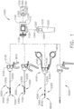
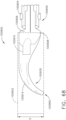
- a surgical instrument system is depicted in FIG. 1 .
- the surgical instrument system comprises a handle assembly 1000 which is selectively usable with a shaft assembly 2000, a shaft assembly 3000, a shaft assembly 4000, a shaft assembly 5000, and/or any other suitable shaft assembly.
- the shaft assembly 2000 is attached to the handle assembly 1000 in FIG. 2 and the shaft assembly 4000 is attached to the handle assembly 1000 in FIG. 45 .
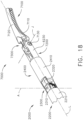
- the shaft assembly 2000 comprises a proximal portion 2100, an elongate shaft 2200 extending from the proximal portion 2100, a distal attachment portion 2400, and an articulation joint 2300 rotatably connecting the distal attachment portion 2400 to the elongate shaft 2200.
- the shaft assembly 2000 further comprises a replaceable end effector assembly 7000 attached to the distal attachment portion 2400.
- the replaceable end effector assembly 7000 comprises a jaw assembly 7100 configured to be opened and closed to clamp and/or manipulate the tissue of a patient.
- the end effector assembly 7000 can be articulated about the articulation joint 2300 and/or rotated relative to the distal attachment portion 2400 about a longitudinal axis to better position the jaw assembly 7100 within the patient, as described in greater detail further below.
- the handle assembly 1000 comprises, among other things, a drive module 1100.
- the drive module 1100 comprises a distal mounting interface which permits a clinician to selectively attach one of the shaft assemblies 2000, 3000, 4000, and 5000, for example, to the drive module 1100.
- each of the shaft assemblies 2000, 3000, 4000, and 5000 comprises an identical, or an at least similar, proximal mounting interface which is configured to engage the distal mounting interface of the drive module 1100.
- the mounting interface of the drive module 1100 mechanically secures and electrically couples the selected shaft assembly to the drive module 1100.
- the drive module 1100 further comprises at least one electric motor, one or more controls and/or displays, and a controller configured to operate the electric motor- the rotational output of which is transmitted to a drive system of the shaft assembly attached to the drive module 1100.
- the drive module 1100 is usable with one ore more power modules, such as power modules 1200 and 1300, for example, which are operably attachable to the drive module 1100 to supply power thereto.
- the handle drive module 1100 comprises a housing 1110, a first module connector 1120, and a second module connector 1120'.
- the power module 1200 comprises a housing 1210, a connector 1220, one or more release latches 1250, and one or more batteries 1230.
- the connector 1220 is configured to be engaged with the first module connector 1120 of the drive module 1100 in order to attach the power module 1200 to the drive module 1100.
- the connector 1220 comprises one or more latches 1240 which mechanically couple and fixedly secure the housing 1210 of the power module 1200 to the housing 1110 of the drive module 1100.
- the latches 1240 are movable into disengaged positions when the release latches 1250 are depressed so that the power module 1200 can be detached from the drive module 1100.
- the connector 1220 also comprises one or more electrical contacts which place the batteries 1230, and/or an electrical circuit including the batteries 1230, in electrical communication with an electrical circuit in the drive module 1100.
- the power module 1300 comprises a housing 1310, a connector 1320, one or more release latches 1350, and one or more batteries 1330 ( FIG. 47 ).
- the connector 1320 is configured to be engaged with the second module connector 1120' of the drive module 1100 to attach the power module 1300 to the drive module 1100.
- the connector 1320 comprises one or more latches 1340 which mechanically couple and fixedly secure the housing 1310 of the power module 1300 to the housing 1110 of the drive module 1100.
- the latches 1340 are movable into disengaged positions when the release latches 1350 are depressed so that the power module 1300 can be detached from the drive module 1100.
- the connector 1320 also comprises one or more electrical contacts which place the batteries 1330 of the power module 1300, and/or an electrical power circuit including the batteries 1330, in electrical communication with an electrical power circuit in the drive module 1100.
- the power module 1200 when attached to the drive module 1100, comprises a pistol grip which can allow a clinician to hold the handle 1000 in a manner which places the drive module 1100 on top of the clinician's hand.
- the power module 1300 when attached to the drive module 1100, comprises an end grip which allows a clinician to hold the handle 1000 like a wand.
- the power module 1200 is longer than the power module 1300, although the power modules 1200 and 1300 can comprise any suitable length.
- the power module 1200 has more battery cells than the power module 1300 and can suitably accommodate these additional battery cells owing to its length.
- the power module 1200 can provide more power to the drive module 1100 than the power module 1300 while, in some instances, the power module 1200 can provide power for a longer period of time.
- the housing 1110 of the drive module 1100 comprises keys, and/or any other suitable features, which prevent the power module 1200 from being connected to the second module connector 1120' and, similarly, prevent the power module 1300 from being connected to the first module connector 1120.
- Such an arrangement can assure that the longer power module 1200 is used in the pistol grip arrangement and that the shorter power module 1300 is used in the wand grip arrangement.
- the power module 1200 and the power module 1300 can be selectively coupled to the drive module 1100 at either the first module connector 1120 or the second module connector 1120'. Such embodiments provide a clinician with more options to customize the handle 1000 in a manner suitable to them.
- the power module 1200 can be in the way when the shaft assembly 4000, for example, is attached to the drive module 1100.
- both of the power modules 1200 and 1300 can be operably coupled to the drive module 1100 at the same time.
- the drive module 1100 can have access to power provided by both of the power modules 1200 and 1300.
- a clinician can switch between a pistol grip and a wand grip when both of the power modules 1200 and 1300 are attached to the drive module 1100.
- such an arrangement allows the power module 1300 to act as a counterbalance to a shaft assembly, such as shaft assemblies 2000, 3000, 4000, or 5000, for example, attached to the drive module 1100.
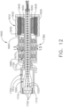
- the handle drive module 1100 further comprises a frame 1500, a motor assembly 1600, a drive system 1700 operably engaged with the motor assembly 1600, and a control system 1800.
- the frame 1500 comprises an elongate shaft that extends through the motor assembly 1600.
- the elongate shaft comprises a distal end 1510 and electrical contacts, or sockets, 1520 defined in the distal end 1510.
- the electrical contacts 1520 are in electrical communication with the control system 1800 of the drive module 1100 via one or more electrical circuits and are configured to convey signals and/or power between the control system 1800 and the shaft assembly, such as the shaft assembly 2000, 3000, 4000, or 5000, for example, attached to the drive module 1100.
- the control system 1800 comprises a printed circuit board (PCB) 1810, at least one microprocessor 1820, and at least one memory device 1830.
- the board 1810 can be rigid and/or flexible and can comprise any suitable number of layers.
- the microprocessor 1820 and the memory device 1830 are part of a control circuit defined on the board 1810 which controls the operation of the motor assembly 1600, as described in greater detail below.
- the motor assembly 1600 comprises an electric motor 1610 including a housing 1620, a drive shaft 1630, and a gear reduction system.
- the electric motor 1610 further comprises a stator including windings 1640 and a rotor including magnetic elements 1650.
- the stator windings 1640 are supported in the housing 1620 and the rotor magnetic elements 1650 are mounted to the drive shaft 1630.
- the drive shaft 1630 is rotated about a longitudinal axis.
- the drive shaft 1630 is operably engaged with a first planetary gear system 1660 which includes a central sun gear and several planetary gears operably intermeshed with the sun gear.
- the sun gear of the first planetary gear system 1660 is fixedly mounted to the drive shaft 1630 such that it rotates with the drive shaft 1630.
- the planetary gears of the first planetary gear system 1660 are rotatably mounted to the sun gear of a second planetary gear system 1670 and, also, intermeshed with a geared or splined inner surface 1625 of the motor housing 1620.
- the rotation of the first sun gear rotates the first planetary gears which rotate the second sun gear.
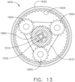
- the second planetary gear system 1670 further comprises planetary gears 1665 ( FIG. 13 ) which drive a third planetary gear system and, ultimately, the drive shaft 1710.
- the planetary gear systems 1660, 1670, and 1680 cooperate to gear down the speed applied to the drive shaft 1710 by the motor shaft 1620.
- Various alternative embodiments are envisioned without a speed reduction system. Such embodiments are suitable when it is desirable to drive the end effector functions quickly.
- the drive shaft 1630 comprises an aperture, or hollow core, extending therethrough through which wires and/or electrical circuits can extend.
- the control system 1800 is in communication with the motor assembly 1600 and the electrical power circuit of the drive module 1100.
- the control system 1800 is configured to control the power delivered to the motor assembly 1600 from the electrical power circuit.
- the electrical power circuit is configured to supply a constant, or at least nearly constant, direct current (DC) voltage. In at least one instance, the electrical power circuit supplies 3 VDC to the control system 1800.
- the control system 1800 comprises a pulse width modulation (PWM) circuit which is configured to deliver voltage pulses to the motor assembly 1600. The duration or width of the voltage pulses, and/or the duration or width between the voltage pulses, supplied by the PWM circuit can be controlled in order to control the power applied to the motor assembly 1600.
- PWM pulse width modulation
- the PWM circuit can control the speed of the output shaft of the motor assembly 1600.
- the control system 1800 can include a frequency modulation (FM) circuit.
- FM frequency modulation
- the control system 1800 is operable in more than one operating mode and, depending on the operating mode being used, the control system 1800 can operate the motor assembly 1600 at a speed, or a range of speeds, which is determined to be appropriate for that operating mode.
- the drive system 1700 comprises a rotatable shaft 1710 comprising a splined distal end 1720 and a longitudinal aperture 1730 defined therein.
- the rotatable shaft 1710 is operably mounted to the output shaft of the motor assembly 1600 such that the rotatable shaft 1710 rotates with the motor output shaft.
- the handle frame 1510 extends through the longitudinal aperture 1730 and rotatably supports the rotatable shaft 1710. As a result, the handle frame 1510 serves as a bearing for the rotatable shaft 1710.
- the handle frame 1510 and the rotatable shaft 1710 extend distally from a mounting interface 1130 of the drive module 1110 and are coupled with corresponding components on the shaft assembly 2000 when the shaft assembly 2000 is assembled to the drive module 1100.
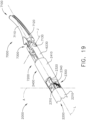
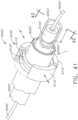
- the shaft assembly 2000 further comprises a frame 2500 and a drive system 2700.
- the frame 2500 comprises a longitudinal shaft 2510 extending through the shaft assembly 2000 and a plurality of electrical contacts, or pins, 2520 extending proximally from the shaft 2510.
- the electrical contacts 2520 on the shaft frame 2510 engage the electrical contacts 1520 on the handle frame 1510 and create electrical pathways therebetween.
- the drive system 2700 comprises a rotatable drive shaft 2710 which is operably coupled to the rotatable drive shaft 1710 of the handle 1000 when the shaft assembly 2000 is assembled to the drive module 1100 such that the drive shaft 2710 rotates with the drive shaft 1710.
- the drive shaft 2710 comprises a splined proximal end 2720 which mates with the splined distal end 1720 of the drive shaft 1710 such that the drive shafts 1710 and 2710 rotate together when the drive shaft 1710 is rotated by the motor assembly 1600.
- the shaft assembly 2000 is assembled to the handle 1000 along a longitudinal axis; however, the operable interconnection between the drive shafts 1710 and 2710 and the electrical interconnection between the frames 1510 and 2510 can comprise any suitable configuration which can allow a shaft assembly to be assembled to the handle 1000 in any suitable manner.
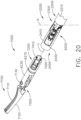
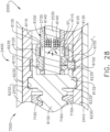
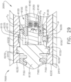
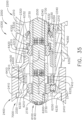
- the first clutch system 6100 comprises a first clutch 6110, an expandable first drive ring 6120, and a first electromagnetic actuator 6140.
- the first clutch 6110 comprises an annular ring and is slideably disposed on the drive shaft 2730.
- the first clutch 6110 is comprised of a magnetic material and is movable between a disengaged, or unactuated, position ( FIG. 28 ) and an engaged, or actuated, position ( FIG. 29 ) by electromagnetic fields EF generated by the first electromagnetic actuator 6140.
- the first clutch 6110 is at least partially comprised of iron and/or nickel, for example.
- the first clutch 6110 comprises a permanent magnet. As illustrated in FIG.
- the shaft assembly 2000"" comprises an end effector lock 6400' configured to releasably lock the end effector 7000', for example, to the shaft assembly 2000"".
- the end effector lock 6400' is similar to the end effector lock 6400 in many respects, most of which will not be discussed herein for the sake of brevity.
- a proximal end 6420' of the lock 6400' comprises a tooth 6422' configured to engage the annular slot 6312 of the third clutch 6310 and releasably hold the third clutch 6310 in its disengaged position. That said, the actuation of the third electromagnetic assembly 6340 can disengage the third clutch 6310 from the end effector lock 6400'.
- the proximal movement of the third clutch 6310 into its engaged position rotates the end effector lock 6400' into a locked position and into engagement with the lock notches 7410 to lock the end effector 7000' to the shaft assembly 2000"".
- the distal movement of the third clutch 6310 into its disengaged position unlocks the end effector 7000' and allows the end effector 7000' to be disassembled from the shaft assembly 2000"".
- an instrument system including a handle and a shaft assembly attached thereto can be configured to perform a diagnostic check to assess the state of the clutch assemblies 6100, 6200, and 6300.
- the control system 1800 sequentially actuates the electromagnetic actuators 6140, 6240, and/or 6340 - in any suitable order - to verify the positions of the clutches 6110, 6210, and/or 6310, respectively, and/or verify that the clutches are responsive to the electromagnetic actuators and, thus, not stuck.
- the control system 1800 can use sensors, including any of the sensors disclosed herein, to verify the movement of the clutches 6110, 6120, and 6130 in response to the electromagnetic fields created by the electromagnetic actuators 6140, 6240, and/or 6340.
- the control system 1800 can perform the diagnostic test at any suitable time, such as when a shaft assembly is attached to the handle and/or when the handle is powered on, for example. If the control system 1800 determines that the instrument system passed the diagnostic test, the control system 1800 can permit the ordinary operation of the instrument system. In at least one instance, the handle can comprise an indicator, such as a green LED, for example, which indicates that the diagnostic check has been passed. If the control system 1800 determines that the instrument system failed the diagnostic test, the control system 1800 can prevent and/or modify the operation of the instrument system.
- the control system 1800 can limit the functionality of the instrument system to only the functions necessary to remove the instrument system from the patient, such as straightening the end effector 7000 and/or opening and closing the jaw assembly 7100, for example.
- the control system 1800 enters into a limp mode.
- the limp mode of the control system 1800 can reduce a current rotational speed of the motor 1610 by any percentage selected from a range of about 75% to about 25%, for example. In one example, the limp mode reduces a current rotational speed of the motor 1610 by 50%. In one example, the limp mode reduces the current rotational speed of the motor 1610 by 75%.
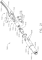
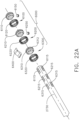
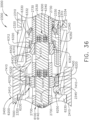
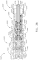
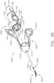
- FIGS. 41-43 depict a clutch system 6000' in accordance with at least one alternative embodiment.
- the clutch system 6000' is similar to the clutch system 6000 in many respects, most of which will not be repeated herein for the sake of brevity.
- the clutch system 6000' comprises a clutch assembly 6100' which is actuatable to selectively couple a rotatable drive input 6030' with a rotatable drive output 6130'.
- the clutch assembly 6100' comprises clutch plates 6110' and drive rings 6120'.
- the clutch plates 6110' are comprised of a magnetic material, such as iron and/or nickel, for example, and can comprise a permanent magnet.
- the clutch system 6000' comprises a clutch actuator 6140' configured to move the clutch plates 6110' into their actuated positions.
- the clutch actuator 6140' is comprised of a magnetic material such as iron and/or nickel, for example, and can comprise a permanent magnet.
- the clutch actuator 6140' is slideably positioned in a longitudinal shaft frame 6050' extending through the drive input 6030' and can be moved between an unactuated position ( FIG. 42 ) and an actuated position ( FIG. 43 ) by a clutch shaft 6060'.
- the clutch shaft 6060' comprises a polymer cable, for example.
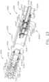
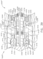
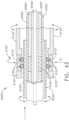
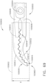
- FIG. 44 depicts an end effector 7000a including a jaw assembly 7100a, a jaw assembly drive, and a clutch system 6000a in accordance with at least one alternative embodiment.
- the jaw assembly 7100a comprises a first jaw 7110a and a second jaw 7120a which are selectively rotatable about a pivot 7130a.
- the jaw assembly drive comprises a translatable actuator rod 7160a and drive links 7140a which are pivotably coupled to the actuator rod 7160a about a pivot 7150a.
- the drive links 7140a are also pivotably coupled to the jaws 7110a and 7120a such that the jaws 7110a and 7120a are rotated closed when the actuator rod 7160a is pulled proximally and rotated open when the actuator rod 7160a is pushed distally.
- the clutch system 6000a is similar to the clutch systems 6000 and 6000' in many respects, most of which will not be repeated herein for the sake of brevity.
- the rotation of the distal outer housing 7220a rotates the jaw assembly 7100a about the longitudinal axis owing to fact that the pivot 7130a of the jaw assembly 7100a is mounted to the distal outer housing 7220a.
- the outer shaft housing 7200a rotates the jaw assembly 7100a in a first direction when the outer shaft housing 7200a is rotated in a first direction by the drive input 6030a.
- the outer shaft housing 7200a rotates the jaw assembly 7100a in a second direction when the outer shaft housing 7200a is rotated in a second direction by the drive input 6030a.
- the electromagnetic actuator 6140a is de-energized, the drive rings 6120a expand and the clutch plates 6110a are moved into their unactuated positions, thereby decoupling the end effector rotation drive from the drive input 6030a.
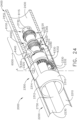
- the second clutch assembly 6200a comprises clutch plates 6210a and drive rings 6220a and work in a manner similar to the clutch plates 6110' and drive rings 6120' discussed above.
- the clutch pates 6210a are actuated by an electromagnetic actuator 6240a, the rotation of the drive input 6030a is transferred to an articulation drive 6230a.
- the articulation drive 6230a is rotatably supported within an outer shaft housing 741 0a of an end effector attachment portion 7400a and is rotatably supported by a shaft frame 6050a extending through the outer shaft housing 7410a.
- the articulation drive 6230a comprises a gear face defined thereon which is operably intermeshed with a stationary gear face 7230a defined on the proximal outer housing 721 0a of the outer shaft housing 7200a.
- the articulation drive 6230a articulates the outer shaft housing 7200a and the jaw assembly 7100a in a first direction when the articulation drive 6230a is rotated in a first direction by the drive input 6030a.
- the articulation drive 6230a articulates the outer shaft housing 7200a and the jaw assembly 7100a in a second direction when the articulation drive 6230a is rotated in a second direction by the drive input 6030a.
- the electromagnetic actuator 6240a is de-energized, the drive rings 6220a expand and the clutch plates 6210a are moved into their unactuated positions, thereby decoupling the end effector articulation drive from the drive input 6030a.
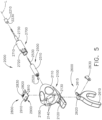
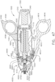
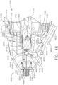
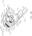
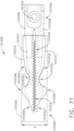
- the shaft assembly 4000 is illustrated in FIGS. 45-49 .
- the shaft assembly 4000 is similar to the shaft assemblies 2000, 2000', 2000′′′, and 2000"" in many respects, most of which will not be repeated herein for the sake of brevity.
- the shaft assembly 4000 comprises a proximal portion 4100, an elongate shaft 4200, a distal attachment portion 2400, and an articulate joint 2300 which rotatably connects the distal attachment portion 2040 to the elongate shaft 4200.
- the proximal portion 4100 similar to the proximal portion 2100, is operably attachable to the drive module 1100 of the handle 1000.
- the proximal portion 4100 comprises a housing 4110 including an attachment interface 4130 configured to mount the shaft assembly 4000 to the attachment interface 1130 of the handle 1000.
- the shaft assembly 4000 further comprises a frame 4500 including a shaft 4510 configured to be coupled to the shaft 1510 of the handle frame 1500 when the shaft assembly 4000 is attached to the handle 1000.
- the shaft assembly 4000 also comprises a drive system 4700 including a rotatable drive shaft 4710 configured to be operably coupled to the drive shaft 1710 of the handle drive system 1700 when the shaft assembly 4000 is attached to the handle 1000.
- the distal attachment portion 2400 is configured to receive an end effector, such as end effector 8000, for example.
- the end effector 8000 is similar to the end effector 7000 in many respects, most of which will not be repeated herein for the sake of brevity. That said, the end effector 8000 comprises a jaw assembly 8100 configured to, among other things, grasp tissue.
- the frame 4500 of the shaft assembly 4000 comprises a frame shaft 4510.
- the frame shaft 4510 comprises a notch, or cut-out, 4530 defined therein.
- the cut-out 4530 is configured to provide clearance for a jaw closure actuation system 4600.
- the frame 4500 further comprises a distal portion 4550 and a bridge 4540 connecting the distal portion 4550 to the frame shaft 4510.
- the frame 4500 further comprises a longitudinal portion 4560 extending through the elongate shaft 4200 to the distal attachment portion 2400. Similar to the above, the frame shaft 4510 comprises one or more electrical traces defined thereon and/or therein.
- the electrical traces extend through the longitudinal portion 4560, the distal portion 4550, the bridge 4540, and/or any suitable portion of the frame shaft 4510 to the electrical contacts 2520.
- the distal portion 4550 and longitudinal portion 4560 comprise a longitudinal aperture defined therein which is configured to receive a rod 4660 of the jaw closure actuation system 4600, as described in greater detail below.
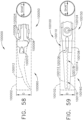
- the drive system 4700 of the shaft assembly 4000 comprises a drive shaft 4710.
- the drive shaft 4710 is rotatably supported within the proximal shaft housing 4110 by the frame shaft 4510 and is rotatable about a longitudinal axis extending through the frame shaft 4510.
- the drive system 4700 further comprises a transfer shaft 4750 and an output shaft 4780.
- the transfer shaft 4750 is also rotatably supported within the proximal shaft housing 4110 and is rotatable about a longitudinal axis extending parallel to, or at least substantially parallel to, the frame shaft 4510 and the longitudinal axis defined therethrough.
- the transfer shaft 4750 comprises a proximal spur gear 4740 fixedly mounted thereto such that the proximal spur gear 4740 rotates with the transfer shaft 4750.
- the proximal spur gear 4740 is operably intermeshed with an annular gear face 4730 defined around the outer circumference of the drive shaft 4710 such that the rotation of the drive shaft 4710 is transferred to the transfer shaft 4750.
- the transfer shaft 4750 further comprises a distal spur gear 4760 fixedly mounted thereto such that the distal spur gear 4760 rotates with the transfer shaft 4750.
- the distal spur gear 4760 is operably intermeshed with an annular gear 4770 defined around the outer circumference of the output shaft 4780 such that the rotation of the transfer shaft 4750 is transferred to the output shaft 4780.
- the output shaft 4780 is rotatably supported within the proximal shaft housing 4110 by the distal portion 4550 of the shaft frame 4500 such that the output shaft 4780 rotates about the longitudinal shaft axis.
- the output shaft 4780 is not directly coupled to the input shaft 4710; rather, the output shaft 4780 is operably coupled to the input shaft 4710 by the transfer shaft 4750.
- Such an arrangement provides room for the manually-actuated jaw closure actuation system 4600 discussed below.
- the jaw closure actuation system 4600 comprises an actuation, or scissors, trigger 4610 rotatably coupled to the proximal shaft housing 4110 about a pivot 4620.
- the actuation trigger 4610 comprises an elongate portion 4612, a proximal end 4614, and a grip ring aperture 4616 defined in the proximal end 4614 which is configured to be gripped by the clinician.
- the shaft assembly 4000 further comprises a stationary grip 4160 extending from the proximal housing 4110.
- the stationary grip 4160 comprises an elongate portion 4162, a proximal end 4164, and a grip ring aperture 4166 defined in the proximal end 4164 which is configured to be gripped by the clinician.
- the actuation trigger 4610 is rotatable between an unactuated position and an actuated position ( FIG. 48 ), i.e., toward the stationary grip 4160, to close the jaw assembly 8100 of the end effector 8000.
- the jaw closure actuation system 4600 further comprises a drive link 4640 rotatably coupled to the proximal shaft housing 4110 about a pivot 4650 and, in addition, an actuation rod 4660 operably coupled to the drive link 4640.
- the actuation rod 4660 extends through an aperture defined in the longitudinal frame portion 4560 and is translatable along the longitudinal axis of the shaft frame 4500.
- the actuation rod 4660 comprises a distal end operably coupled to the jaw assembly 8100 and a proximal end 4665 positioned in a drive slot 4645 defined in the drive link 4640 such that the actuation rod 4660 is translated longitudinally when the drive link 4640 is rotated about the pivot 4650.
- the proximal end 4665 is rotatably supported within the drive slot 4645 such that the actuation rod 4660 can rotate with the end effector 8000.
- the distal rotation of the drive link 4640 drives, and automatically rotates, the actuation trigger 4610 back into its unactuated position. That being said, the clinician could manually return the actuation trigger 4610 back into its unactuated position. In such instances, the actuation trigger 4610 could be opened slowly.
- the shaft assembly 4000 further comprises a lock configured to releasably hold the actuation trigger 4610 in its actuated position such that the clinician can use their hand to perform another task without the jaw assembly 8100 opening unintentionally.
- the actuation rod 4660 can be pushed distally to close the jaw assembly 8100.
- the actuation rod 4660 is mounted directly to the actuation trigger 4610 such that, when the actuation trigger 4610 is actuated, the actuation trigger 4610 drives the actuation rod 4660 distally.
- the actuation trigger 4610 can compress a spring when the actuation trigger 4610 is closed such that, when the actuation trigger 4610 is released, the actuation rod 4660 is pushed proximally.
- the shaft assembly 4000 has three functions - opening/closing the jaw assembly of an end effector, rotating the end effector about a longitudinal axis, and articulating the end effector about an articulation axis.
- the end effector rotation and articulation functions of the shaft assembly 4000 are driven by the motor assembly 1600 and the control system 1800 of the drive module 1100 while the jaw actuation function is manually-driven by the jaw closure actuation system 4600.
- the jaw closure actuation system 4600 could be a motor-driven system but, instead, the jaw closure actuation system 4600 has been kept a manually-driven system such that the clinician can have a better feel for the tissue being clamped within the end effector.
- motorizing the jaw closure actuation system 4600 may cause the clinician to lose a tactile sense of the force being applied to the tissue and may not be able to assess whether the force is insufficient or excessive. Thus, the jaw closure actuation system 4600 is manually-driven even though the end effector rotation and articulation systems are motor-driven.
- FIG. 50 is a logic diagram of the control system 1800 of the surgical system depicted in FIG. 1 in accordance with at least one embodiment.
- the control system 1800 comprises a control circuit.
- the control circuit includes a microcontroller 1840 comprising a processor 1820 and a memory 1830.
- One or more sensors such as sensors 1880, 1890, 6180', 6280', 6380', 7190", and/or 6290′′′, for example, provide real time feedback to the processor 1820.
- the control system 1800 further comprises a motor driver 1850 configured to control the electric motor 1610 and a tracking system 1860 configured to determine the position of one or more longitudinally movable components in the surgical instrument, such as the clutches 6110, 6120, and 6130 and/or the longitudinally-movable drive nut 7150 of the jaw assembly drive, for example.
- the tracking system 1860 is also configured to determine the position of one or more rotational components in the surgical instrument, such as the drive shaft 2530, the outer shaft 6230, and/or the articulation drive 6330, for example.
- the tracking system 1860 provides position information to the processor 1820, which can be programmed or configured to, among other things, determine the position of the clutches 6110, 6120, and 6130 and the drive nut 7150 as well as the orientation of the jaws 7110 and 7120.
- the motor driver 1850 may be an A3941 available from Allegro Microsystems, Inc., for example; however, other motor drivers may be readily substituted for use in the tracking system 1860.
- a detailed description of an absolute positioning system is described in U.S. Patent Application Publication No. 2017/0296213 , entitled SYSTEMS AND METHODS FOR CONTROLLING A SURGICAL STAPLING AND CUTTING INSTRUMENT, the entire disclosure of which is hereby incorporated herein by reference.
- the microcontroller 1840 may be any single core or multicore processor such as those known under the trade name ARM Cortex by Texas Instruments, for example.
- the microcontroller 1840 is a LM4F230H5QR ARM Cortex-M4F Processor Core, available from Texas Instruments, for example, comprising on-chip memory of 256 KB single-cycle flash memory, or other non-volatile memory, up to 40 MHz, a prefetch buffer to improve performance above 40 MHz, a 32 KB single-cycle serial random access memory (SRAM), internal read-only memory (ROM) loaded with StellarisWare ® software, 2 KB electrically erasable programmable read-only memory (EEPROM), one or more pulse width modulation (PWM) modules and/or frequency modulation (FM) modules, one or more quadrature encoder inputs (QEI) analog, one or more 12-bit Analog-to-Digital Converters (ADC) with 12 analog input channels, for example, details of which are available from the product
- the microcontroller 1840 comprises a safety controller comprising two controller-based families such as TMS570 and RM4x known under the trade name Hercules ARM Cortex R4, also by Texas instruments.
- the safety controller may be configured specifically for IEC 61508 and ISO 26262 safety critical applications, among others, to provide advanced integrated safety features while delivering scalable performance, connectivity, and memory options.
- the microcontroller 1840 is programmed to perform various functions such as precisely controlling the speed and/or position of the drive nut 7150 of the jaw closure assembly, for example.
- the microcontroller 1840 is also programmed to precisely control the rotational speed and position of the end effector 7000 and the articulation speed and position of the end effector 7000.
- the microcontroller 1840 computes a response in the software of the microcontroller 1840.
- the computed response is compared to a measured response of the actual system to obtain an "observed" response, which is used for actual feedback decisions.
- the observed response is a favorable, tuned, value that balances the smooth, continuous nature of the simulated response with the measured response, which can detect outside influences on the system.
- the motor 1610 is controlled by the motor driver 1850.
- the motor 1610 is a DC brushed driving motor having a maximum rotational speed of approximately 25,000 RPM, for example.
- the motor 1610 includes a brushless motor, a cordless motor, a synchronous motor, a stepper motor, or any other suitable electric motor.
- the motor driver 1850 may comprise an H-bridge driver comprising field-effect transistors (FETs), for example.
- FETs field-effect transistors
- the motor driver 1850 may be an A3941 available from Allegro Microsystems, Inc., for example.
- the A3941 driver 1850 is a full-bridge controller for use with external N-channel power metal oxide semiconductor field effect transistors (MOSFETs) specifically designed for inductive loads, such as brush DC motors.
- MOSFETs power metal oxide semiconductor field effect transistors
- the driver 1850 comprises a unique charge pump regulator provides full (>10 V) gate drive for battery voltages down to 7 V and allows the A3941 to operate with a reduced gate drive, down to 5.5 V.
- a bootstrap capacitor may be employed to provide the above-battery supply voltage required for N-channel MOSFETs.
- An internal charge pump for the high-side drive allows DC (100% duty cycle) operation.
- the full bridge can be driven in fast or slow decay modes using diode or synchronous rectification. In the slow decay mode, current recirculation can be through the high-side or the lowside FETs.
- the power FETs are protected from shoot-through by resistor adjustable dead time.
- Integrated diagnostics provide indication of undervoltage, overtemperature, and power bridge faults, and can be configured to protect the power MOSFETs under most short circuit conditions. Other motor drivers may be readily substituted.
- the tracking system 1860 comprises a controlled motor drive circuit arrangement comprising one or more position sensors, such as sensors 1880, 1890, 6180', 6280', 6380', 7190", and/or 6290′′′, for example.
- the position sensors for an absolute positioning system provide a unique position signal corresponding to the location of a displacement member.
- displacement member is used generically to refer to any movable member of the surgical system.
- the displacement member may be coupled to any position sensor suitable for measuring linear displacement.
- Linear displacement sensors may include contact or non-contact displacement sensors.
- Linear displacement sensors may comprise linear variable differential transformers (LVDT), differential variable reluctance transducers (DVRT), a slide potentiometer, a magnetic sensing system comprising a movable magnet and a series of linearly arranged Hall Effect sensors, a magnetic sensing system comprising a fixed magnet and a series of movable linearly arranged Hall Effect sensors, an optical sensing system comprising a movable light source and a series of linearly arranged photo diodes or photo detectors, or an optical sensing system comprising a fixed light source and a series of movable linearly arranged photo diodes or photo detectors, or any combination thereof.
- LVDT linear variable differential transformers
- DVRT differential variable reluctance transducers
- slide potentiometer a magnetic sensing system comprising a movable magnet and a series of linearly arranged Hall Effect sensors
- a magnetic sensing system comprising a fixed magnet and a series of movable linearly arranged Hall Effect sensors
- the position sensors 1880, 1890, 6180', 6280', 6380', 7190", and/or 6290′′′ may comprise any number of magnetic sensing elements, such as, for example, magnetic sensors classified according to whether they measure the total magnetic field or the vector components of the magnetic field.
- magnetic sensors classified according to whether they measure the total magnetic field or the vector components of the magnetic field.
- the techniques used to produce both types of magnetic sensors encompass many aspects of physics and electronics.
- the technologies used for magnetic field sensing include search coil, fluxgate, optically pumped, nuclear precession, SQUID, Hall-Effect, anisotropic magnetoresistance, giant magnetoresistance, magnetic tunnel junctions, giant magnetoimpedance, magnetostrictive/piezoelectric composites, magnetodiode, magnetotransistor, fiber optic, magnetooptic, and microelectromechanical systems-based magnetic sensors, among others.
- one or more of the position sensors of the tracking system 1860 comprise a magnetic rotary absolute positioning system.
- Such position sensors may be implemented as an AS5055EQFT single-chip magnetic rotary position sensor available from Austria Microsystems, AG and can be interfaced with the controller 1840 to provide an absolute positioning system.
- a position sensor comprises a low-voltage and low-power component and includes four Hall-Effect elements in an area of the position sensor that is located adjacent a magnet.
- a high resolution ADC and a smart power management controller are also provided on the chip.
- a CORDIC processor for Coordinate Rotation Digital Computer, also known as the digit-by-digit method and Volder's algorithm, is provided to implement a simple and efficient algorithm to calculate hyperbolic and trigonometric functions that require only addition, subtraction, bitshift, and table lookup operations.
- the angle position, alarm bits, and magnetic field information are transmitted over a standard serial communication interface such as an SPI interface to the controller 1840.
- the position sensors can provide 12 or 14 bits of resolution, for example.
- the position sensors can be an AS5055 chip provided in a small QFN 16-pin 4x4x0.85mm package, for example.
- the tracking system 1860 may comprise and/or be programmed to implement a feedback controller, such as a PID, state feedback, and adaptive controller.
- a power source converts the signal from the feedback controller into a physical input to the system, in this case voltage.
- Other examples include pulse width modulation (PWM) and/or frequency modulation (FM) of the voltage, current, and force.
- PWM pulse width modulation
- FM frequency modulation
- Other sensor(s) may be provided to measure physical parameters of the physical system in addition to position.
- the other sensor(s) can include sensor arrangements such as those described in U.S. Patent No. 9,345,481 , entitled STAPLE CARTRIDGE TISSUE THICKNESS SENSOR SYSTEM, which is hereby incorporated herein by reference in its entirety; U.S. Patent Application Publication No.
- the absolute positioning system may comprise a compare and combine circuit to combine a computed response with a measured response using algorithms such as weighted average and theoretical control loop that drives the computed response towards the measured response.
- the computed response of the physical system takes into account properties like mass, inertial, viscous friction, inductance resistance, etc., to predict what the states and outputs of the physical system will be by knowing the input.
- the absolute positioning system provides an absolute position of the displacement member upon power up of the instrument without retracting or advancing the displacement member to a reset (zero or home) position as may be required with conventional rotary encoders that merely count the number of steps forwards or backwards that the motor 1610 has taken to infer the position of a device actuator, drive bar, knife, and the like.
- a sensor 1880 comprising a strain gauge or a micro-strain gauge, for example, is configured to measure one or more parameters of the end effector, such as, for example, the strain experienced by the jaws 7110 and 7120 during a clamping operation. The measured strain is converted to a digital signal and provided to the processor 1820.
- a sensor 1890 comprising a load sensor, for example, can measure the closure force applied by the closure drive system to the jaws 7110 and 7120.
- a current sensor 1870 can be employed to measure the current drawn by the motor 1610.
- the force required to clamp the jaw assembly 7100 can correspond to the current drawn by the motor 1610, for example.
- the measured force is converted to a digital signal and provided to the processor 1820.
- a magnetic field sensor can be employed to measure the thickness of the captured tissue. The measurement of the magnetic field sensor can also be converted to a digital signal and provided to the processor 1820.
- the measurements of the tissue compression, the tissue thickness, and/or the force required to close the end effector on the tissue as measured by the sensors can be used by the controller 1840 to characterize the position and/or speed of the movable member being tracked.
- a memory 1830 may store a technique, an equation, and/or a look-up table which can be employed by the controller 1840 in the assessment.
- the controller 1840 can provide the user of the surgical instrument with a choice as to the manner in which the surgical instrument should be operated.
- the display 1440 can display a variety of operating conditions of the instrument and can include touch screen functionality for data input.
- information displayed on the display 1440 may be overlaid with images acquired via the imaging modules of one or more endoscopes and/or one or more additional surgical instruments used during the surgical procedure.
- the drive module 1100 of the handle 1000 and/or the shaft assemblies 2000, 3000, 4000, and/or 5000, for example, attachable thereto comprise control systems.
- Each of the control systems can comprise a circuit board having one or more processors and/or memory devices.
- the control systems are configured to store sensor data, for example. They are also configured to store data which identifies the shaft assembly to the handle 1000. Moreover, they are also configured to store data including whether or not the shaft assembly has been previously used and/or how many times the shaft assembly has been used. This information can be obtained by the handle 1000 to assess whether or not the shaft assembly is suitable for use and/or has been used less than a predetermined number of times, for example.
- a drive module 1100' in accordance with at least one alternative embodiment is illustrated in FIGS. 51-53 .
- the drive module 1100' is similar to the drive module 1100 in many respects, most of which will not be discussed herein for the sake of brevity.
- the drive module 1100' comprises an actuator 1420' configured to control the rotation and articulation of the end effector 7000. Similar to the actuator 1420, discussed above, the actuator 1420' is rotatable about a longitudinal axis LA that extends through a shaft assembly attached to the drive module 1100.
- the longitudinal axis LA extends through the center, or substantially the center, of the elongate shaft 2200 of the shaft assembly 3000 ( FIG. 1 ) when the shaft assembly 3000 is assembled to the drive module 1100'.
- the longitudinal axis LA also extends through the center, or substantially the center, of the end effector 7000 when the end effector 7000 is attached to the shaft assembly 3000, for example.
- the actuator 1420' is rotatable within a channel 1190' defined in the housing 1110 in a first direction to rotate the end effector 7000 in the first direction and, similarly, in a second, or opposite, direction to rotate the end effector 7000 in the second direction.
- the drive module 1100' comprises a sensor system in communication with the control system 1800 configured to detect the rotation of the actuator 1420' about the longitudinal axis LA.
- the sensor system comprises a first sensor 1422' configured to detect the rotation of the actuator 1420' about the longitudinal axis LA in the first direction ( FIG. 52A ) and a second sensor 1424' configured to detect the rotation of the actuator 1420' about the longitudinal axis LA in the second direction ( FIG.
- the first and second sensors 1422' and 1424' comprise Hall Effect sensors, for example, but could comprise any suitable type of sensor.
- the actuator 1420' comprises a center magnetic element 1426' positioned in the top of the actuator 1420' which is detectable by the first and second sensors 1422' and 1424' to determine the rotation of the actuator 1420'.
- the center magnetic element 1426' can comprise a permanent magnet and/or can be comprised of iron and/or nickel, for example.
- control system 1800 is configured to control the motor assembly 1600 and the clutch system 6000 to rotate the end effector 7000 about the longitudinal axis LA in the first direction when the actuator 1420' is rotated about the longitudinal axis LA in the first direction.
- control system 1800 is configured to control the motor assembly 1600 and the clutch system 6000 to rotate the end effector 7000 about the longitudinal axis LA in the second direction when the actuator 1420' is rotated about the longitudinal axis LA in the second direction.
- the end effector 7000 is configured to rotate about a longitudinal axis within a socket defined in the distal attachment portion 2400 of the shaft assembly 2000. Depending on the amount of rotation desired, the end effector 7000 can be rotated less than 360 degrees or more than 360 degrees in either direction. In various instances, the end effector 7000 can be rotated through several rotations in either direction. In alternative embodiments, the rotation of the end effector 7000 about the longitudinal axis can be limited. In at least one embodiment, the shaft assembly 2000 comprises one or more stops which limit the rotation of the end effector 7000 to less than one rotation.
- control system 1800 monitors the rotation of the drive shaft 1710, such as by an encoder and/or an absolute positioning sensor system, for example, and limits the rotation of the end effector 7000 by stopping or pausing the motor 1610 when the end effector 7000 has reached the end of its permitted range. In at least one instance, the control system 1800 can disengage the second clutch 6210 from the drive shaft 2730 to stop or pause the rotation of the end effector 7000 when the end effector 7000 has reached the end of its permitted range.
- the drive module 1100' and/or a shaft module attached to the drive module 1100' can provide feedback to the clinician that the end effector 7000 has reached the end of its rotation.
- the drive module 1100' and/or the shaft module attached thereto can comprise an indicator light 1427', such as a red LED, for example, on a first side of the module housing 1110' which is illuminated by the control system 1800 when the end effector 7000 has reached the end of its permitted rotation in the first direction, as illustrated in FIG. 52A .
- the drive module 1100' and/or the shaft module attached thereto can comprise an indicator light 1429', such as a red LED, for example, on a second side of the module housing 1110' which is illuminated by the control system 1800 when the end effector 7000 has reached the end of its permitted rotation in the second direction, as illustrated in FIG. 52B .
- the illumination of either the first light 1427' or the second light 1429' can indicate to the clinician that the motor 1610 has been paused and that the end effector 7000 is no longer rotating.
- the first light 1427' and/or the second light 1429' can blink when the motor 1610 is paused.
- the drive module 1100' and/or the shaft assembly attached thereto can comprise an annular series, or array, of indicator lights 1428' extending around the perimeter thereof which is in communication with the control system 1800 and can indicate the rotational orientation of the end effector 7000.
- the control system 1800 is configured to illuminate the particular indicator light which corresponds, or at least substantially corresponds, with the position in which the top of the end effector 7000 is oriented.
- the center of the first jaw 7110 can be deemed the top of the end effector 7000, for example. In such instances, the illuminated light indicates the top-dead-center position of the end effector 7000.
- control system 1800 can illuminate the particular indicator light which corresponds, or at least substantially corresponds, with the position in which the bottom, or bottom-dead-center, of the end effector 7000 is oriented.
- the center of the second jaw 7210 can be deemed the bottom of the end effector 7000, for example.
- the illuminated indicator light can follow the rotation of the end effector 7000 around the array of indicator lights 1428'.
- the actuator 1420' is also rotatable, or tiltable, about a transverse axis TA within the housing channel 1190'.
- the sensor system of the drive module 1100' is further configured to detect the rotation of the actuator 1420' about the transverse axis TA in a first tilt direction and a second tilt direction.
- the sensor system comprises a first tilt sensor 1423' configured to detect the rotation of the actuator 1420' about the longitudinal axis TA in the first tilt direction ( FIG. 53A ) and a second tilt sensor 1425' configured to detect the rotation of the actuator 1420' in the second tilt direction ( FIG. 53B ).
- the first and second tilt sensors 1423' and 1425' comprise Hall Effect sensors, for example, but could comprise any suitable type of sensor.
- the actuator 1420' further comprises a first lateral magnetic element adjacent the first tilt sensor 1423', the motion of which is detectable by the first tilt sensor 1423'.
- the actuator 1420' also comprises a second lateral magnetic element adjacent the second tilt sensor 1425', the motion of which is detectable by the second tilt sensor 1425'.
- the first and second lateral magnetic elements can comprise a permanent magnet and/or can be comprised of iron and/or nickel, for example. As illustrated in FIGS.
- the lateral sides of the actuator 1420' are movable proximally and distally about the transverse axis TA and, as a result, the first and second lateral magnetic elements are also movable proximally and distally relative to the first and second tilt sensors.
- the reader should appreciate that, while the first and second lateral magnetic elements actually travel along arcuate paths about the transverse axis TA, the distances in which the first and second lateral magnetic elements move is small and, as a result, the arcuate motion of the first and second lateral magnetic elements approximates translation in the proximal and distal directions.
- the entire actuator 1420' comprises a magnetic ring of material which is detectable by the tilt sensors 1423' and 1425' of the drive module 1100'.
- the rotation of the actuator 1420' about the longitudinal axis LA would not create a compound motion relative to the tilt sensors when the actuator 1420' is tilted.
- the magnetic ring of material can comprise a permanent magnet and/or can be comprised of iron and/or nickel, for example.
- the control system 1800 operates the motor assembly 1600 and the clutch system 6000 to articulate the end effector 7000 about the articulation joint 2300 in the first direction.
- the control system 1800 operates the motor assembly 1600 and the clutch system 6000 to articulate the end effector 7000 about the articulation joint 2300 in the second direction when the sensor system detects that the actuator 1420' has been tilted in the second direction, as illustrated in FIG. 53B .
- the actuator 1420' comprises a biasing system configured to center the actuator 1420' in its unrotated and untilted position.
- the biasing system comprises first and second rotation springs configured to center the actuator 1420' in its unrotated position and first and second tilt springs configured to center the actuator 1420' in its untilted position.
- These springs can comprise torsion springs and/or linear displacement springs, for example.
- the end effector 7000 rotates relative to the distal attachment portion 2400 of the shaft assembly 3000.
- Such an arrangement allows the end effector 7000 to be rotated without having to rotate the shaft assembly 3000, although embodiments are possible in which an end effector and shaft assembly rotate together. That said, by rotating the end effector 7000 relative to the shaft assembly 3000, all of the rotation of the surgical system occurs distally relative to the articulation joint 2300. Such an arrangement prevents a large sweep of the end effector 7000 when the end effector 7000 is articulated and then rotated.
- the articulation joint 2300 does not rotate with the end effector 7000 and, as a result, the articulation axis of the articulation joint 2300 is unaffected by the rotation of the end effector 7000.
- the transverse axis TA does not rotate with the actuator 1420'; rather, the transverse axis TA remains stationary with respect to the drive module 1100'. That said, in alternative embodiments, the transverse axis TA can rotate, or track the end effector 7000, when the articulation joint rotates with the end effector. Such an arrangement can maintain an intuitive relationship between the motion of the actuator 1420' and the motion of the end effector 7000.
- the vibration can confirm to the clinician that the drive shaft 1710" is rotating and that one of the clutches in the clutch system 6000 is engaged with the drive shaft 1710".
- the clutch 1730" can be actuated when the jaw assembly 7100, for example, has reached or is reaching its closed position such that the clinician knows that the tissue has been clamped within the jaw assembly 7100 and that the surgical instrument can be used to manipulate the tissue.
- the tactile feedback system, and/or any other feedback system, of the drive module 1100" can be used to provide tactile feedback when appropriate.
- a surgical instrument may have a surgical end effector 100100, as illustrated in FIG. 59 .
- the surgical end effector 100100 has a standard connection portion 100150 and a customizable end effector portion 100160.
- the standard connection portion 100150 includes a first jaw portion 100106 and a second jaw portion 100108.
- the first jaw portion 100106 and the second jaw portion 100108 are rotatable about a joint 100104.
- the standard connection portion 100150 of the surgical end effector 100100 can be connected to a shaft of a surgical instrument.
- the shaft of the surgical instrument can have a diameter D.
- the customizable end effector portion 100160 can be customized within the customization region 100102 such that the diameter of the customization region 100102 is equal to or less than the diameter D of the shaft of the surgical instrument. With the customizable end effector portion 100160 being confined to the bounds of the customization region 100102, the surgical end effector 100100 can be inserted through a trocar into a patient's body cavity through minimally invasive surgical procedures.
- the first jaw portion 100306 of the end effector portion 100360 includes a core/stub portion 100310 that is adaptable through additive manufacturing techniques.
- the core/stub portion 100310 provides a base for building and customizing the geometry and characteristics of a first customizable jaw 100312 and a second customizable jaw 100314.
- the first customizable jaw 100312 and the second customizable jaw 100314 can be modified and adapted to meet the needs of the surgeon.
- the first customizable jaw 100312 and the second customizable jaw 100314 have a plurality of proximal features 100318 and a plurality of distal features 100316. As illustrated in FIG. 61 , the plurality of proximal features 100318 comprises a plurality of proximal teeth.
- FIG. 70 depicts a top plan view of the surgical end effector 101000.
- FIG. 71 depicts a side elevation view of the surgical end effector 101000.
- the overall geometric shape of the surgical end effector 101000 is a substantially linear configuration.
- the external features 101030a-d, 101032a-d, the proximal features 101018, the distal features 101016, the overall geometric shape of the first and second customizable jaws 101012, 101014, and the materials used in producing the customizable end effector portion 101060 are independent variables that are considered during the customization process.
- the various independent variables must produce an overall profile that falls within the customization region 101002 so that the surgical end effector 101000 can be inserted through a trocar and into a patient's body cavity.
- the various end effectors described above with respect to FIGS. 58-71 can be produced through a multi-step process where a first portion of the end effector, such as, a standard connection portion, for example, is produced in a manufacturing facility and shipped to hospitals or distributed to manufacturing hubs. Once the standard connection portion is at its end location, such as a hospital, or at a manufacturing facility, the standard connection portion can be customized to produce an end effector meeting the needs of the user. Such customization can allow surgical end effectors to be produced for specific procedures and/or specific patients.
- the customized end effectors described above with respect to FIGS. 58-71 can be produced through various techniques.
- a clinician can access, for example, a dedicated human-machine interface to select and design the desired attributes of an end effector.
- the human-machine interface can comprise, for example, a graphical user interface of a computer.
- the computer can be connected to a manufacturing device.
- the computer-manufacturing device interface can be wired, wireless, and/or remote, for example, via the internet.
- the clinician can use information gained from the patient or information about the particular procedure to guide their design of the end effector.
- the clinician is using information regarding a particular patient, for example, the patient's information can come from various patient tests, such as MRIs, X-rays, CT Scans, and/or other medical tests. These testing results can be entered into the computer and used to control the design parameters of the end effector.
- the clinician uses the results of an MRI, for example, to detect a patient's tumor, the size and shape of the patient's tumor can be used as design parameters when producing the customized end effector.
- the clinician can use parameters from the particular surgical procedure to design the customized end effector.
- the requirements of the specific procedure such as the size of a gastric bypass reduction, can be used as the design parameters when producing the customized end effector.
- the clinician can use various software programs to design the desired features of the end effector.
- the clinician for example, can input the patient's scans and/or medical test information into the computer and a software program can determine the design features of the end effector to match the patient's condition. Once the software program approximates the necessary features of the end effector, the clinician can review and/or modify the parameters of the end effector using the human-machine interface.
- the clinician can access a software program using the human-machine interface to design the features of the end effector.
- the clinician can access the software program and select various predetermined shapes, features, and/or designs to combine to produce an end effector having the desired features.
- the clinician may also use a free-form command in the software to freely design the desired features of the end effector.
- the clinician and/or manufacturing staff can insert a core/stub portion into a manufacturing device.
- the manufacturing device is in communication with the human-machine interface of the computer via a wired, wireless, and/or remote internet connection.
- the clinician using the software program, can send the design parameters to the manufacturing device to produce the end effector.
- the manufacturing device can be designed to use various manufacturing processes or techniques.
- the manufacturing device for example, can be a metal injection molding device, a plastic injection molding device, a CNC machine, an EDM device, a 3-D printing device, and/or various other manufacturing devices, such as additive manufacturing devices.
- the software controlling the manufacturing device causes the manufacturing device to perform a manufacturing procedure to produce the customized end effector.
- the manufacture procedure can add material to the core/stub portion of the end effector.
- the manufacturing procedure can remove material from the core/stub portion of the end effector.
- the manufacturing device can use one or more of the techniques described above in the production of the customized end effector.
- the customized end effector can be finished or polished using a finishing machine and/or process.
- the finishing machine may be part of the manufacturing device, or it can be a separate machine/device.
- the customized end effector can be tested, cleaned, and/or sterilized.
- the testing process can ensure that the customized end effector is designed to the necessary standards for the particular medical device.
- the cleaning process can remove any excess residual material leftover from the manufacturing process.
- the sterilization process can sterilize the end effector so that it can be used in a surgical procedure. After the customized end effector is sterilized, it can be packaged for storing until it is needed in a surgical procedure or can be used directly by a clinician in a surgical procedure.
- a method for producing a customized end effector comprises preparing an end effector connection portion for customization.
- the end effector connection portion comprises a proximal connector configured to attach to a distal end of a surgical instrument.
- the proximal connector comprises an actuator.
- Surgical instruments can comprise devices that use mechanical energy to perform surgical procedures.
- Certain end effectors such as grasping forceps can be used to grasp a target, such as the tissue of a patient, for example.
- Other end effectors such as dissectors, for example, can be used to separate and/or tear the tissue using mechanical forces.
- Other types of end effectors such as electrosurgical end effectors, for example, can use electrosurgical energy to deliver energy to the tissue of a patient and destroy and/or remove targeted tissue.
- Surgical dissectors such as the dissectors disclosed in U.S. Patent Application Publication No. 2010/0198248 , entitled SURGICAL DISSECTOR, the disclosure of which is incorporated by reference in its entirety, for example, use mechanical forces and mechanical features on the jaws of the dissector, such as teeth, for example, to manipulate a patient's tissue.
- the teeth can be used to stretch and/or tear a patient's tissue.
- the mechanical dissector can apply various amounts of mechanical force to the tissue.
- Surgical dissectors comprise a pair of jaws that are rotatable between open and closed positions.
- Each jaw can comprise a plurality of features, such as teeth or ridges that can engage a patient's tissue on inner and/or outer surfaces of the jaw, for example.
- the features, such as teeth, on the inner surfaces of a pair of surgical dissector jaws can be used to gasp and/or manipulate tissue when the jaws are closed upon a portion of the patient's tissue.
- a pair of surgical dissector jaws comprise teeth and/or ridges on outer surfaces thereof, such teeth can increase the traction and interaction between the jaws and the patient's tissue when the jaws are moved into an open position, for example.
- the teeth on the outer surfaces of the jaws can grip, stretch, and/or tear the tissue.
- Electrosurgical devices for applying electrical energy to tissue in order to treat and/or destroy the tissue are finding increasingly widespread applications in surgical procedures.
- An electrosurgical device typically includes a handpiece and an instrument having a distally-mounted end effector (e.g., one or more electrodes). The end effector can be positioned against the tissue such that electrical current is introduced into the tissue.
- Electrosurgical devices can be configured for bipolar and/or monopolar operation. During bipolar operation, current is introduced into and returned from the tissue by active and return electrodes, respectively, of the end effector. During monopolar operation, current is introduced into the tissue by an active electrode of the end effector and returned through a return electrode (e.g., a grounding pad) separately located on a patient's body.
- a return electrode e.g., a grounding pad
- Heat generated by the current flowing through the tissue may form hemostatic seals within the tissue and/or between tissues and thus may be particularly useful for sealing blood vessels, for example.
- the voltage and current used ablates the tissue.
- the end effector of an electrosurgical device also may include a cutting member that is movable relative to the tissue and the electrodes to transect the tissue.
- the electrical energy applied by an electrosurgical device can be transmitted to the instrument by a generator in communication with the handpiece.
- the electrical energy may be in the form of radio frequency (RF) energy that may be in a frequency range described in EN 60601-2-2:2009+A11:2011, Definition 201.3.218 - HIGH FREQUENCY, the entire disclosure of which is incorporated by reference.
- RF radio frequency
- the frequencies in monopolar RF applications are typically restricted to less than 5MHz, for example.
- the frequency can be any suitable frequency. Frequencies above 200 kHz can be typically used for monopolar applications in order to avoid the unwanted stimulation of nerves and muscles which would result from the use of low frequency current, for instance.
- an electrosurgical device can transmit low frequency RF energy through tissue, which causes ionic agitation, or friction - in effect resistive heating - thereby increasing the temperature of the affected tissue. Because a sharp boundary is created between the affected tissue and the surrounding tissue, a surgeon can operate with a high level of precision and control without sacrificing un-targeted adjacent tissue.
- the low operating temperatures of RF energy is useful for removing, shrinking, and/or sculpting soft tissue while simultaneously sealing blood vessels. RF energy works particularly well on connective tissue, which is primarily comprised of collagen and shrinks when contacted by heat.
- FIGS. 72-79 illustrate surgical instruments that comprise the mechanical features of surgical dissectors and the electrosurgical features of electrosurgical devices.
- the combination of surgical dissector and electrosurgical instrument can allow the surgical instruments illustrated in FIGS. 72-79 to perform various surgical procedures.
- the combination of the mechanical and electrosurgical features may allow a surgeon to perform a surgical procedure without having to switch between different surgical instruments.
- the combination of a mechanical dissector and an electrosurgical instrument can provide synergistic effects and improve the overall efficiencies and abilities of surgical end effectors.
- FIGS. 72-79 illustrate various end effector jaws comprising mechanical dissector features and electrosurgical device features. These end effector jaws can be used with surgical instruments to deliver mechanical as well as electrical energy to a patient's tissue.
- the surgical instruments can comprise proximal and distal end effector portions.
- the proximal portion may include a user interface, such as a handle portion and/or a connector that can connect the surgical instrument to a robotic system, for example.
- the distal portion of the surgical instruments can comprise a surgical end effector.
- the surgical end effector can comprise a pair of jaws that are rotatable between open and closed positions.
- the embodiments disclosed in FIGS. 72-79 illustrate an end effector jaw that can be used in a pair of jaws of a surgical end effector.
- FIGS. 72-75 illustrate a surgical end effector jaw 101100 comprising a frame 101102, a metallic core 101130, and a covering 101126.
- the end effector jaw 101100 comprises an inner surface 101118 and an outer surface 101108.
- the inner surfaces 101118 of the end effector jaws 101100 are positioned adjacent one another.
- the outer surfaces, 101108 of the end effector jaw 101100 are positioned on opposite sides of the end effector jaw 101100.
- the frame 101102 of the surgical end effector jaw 101100 comprises a socket 101104.
- the sockets 101104 of the two end effector jaws 101100 are aligned and a pin can be inserted through the sockets 101104.
- the pair of end effector jaws 101100 can be rotated about the pin between open and closed positions.
- the surgical instrument can also comprise an actuator that can move the end effector jaws 101100 between open and closed positions.
- the surgical end effector jaw 101100 comprises a proximal portion 101106 and a distal portion 101110.
- the overall geometry of the end effector jaw 101100 is curved between the proximal portion 101106 and the distal portion 101110.
- the end effector jaw 101100 is tapered from the wider proximal portion 101106 to the narrower distal portion 101110.
- the tapered profile of the end effector jaw 101100 can permit a surgeon to target a specific location within a patient.
- the surgical end effector jaw 101100 can comprise other geometries, such as a symmetrical geometry and/or and a tapered geometry with a larger distal portion 101110 and a narrower proximal portion 101106, for example.
- the surgical end effector jaw 101100 can grasp a patient's tissue evenly over the entire end effector jaw 101100.
- the surgical end effector jaw 101100 comprises a tapered geometry with a larger distal portion 101110 and a narrower proximal portion 101106
- the larger distal portion 101110 can allow the surgical end effector 101100 to grasp a larger portion of the patient's tissue.
- the proximal portion 101106 of the outer surface 101108 comprises a substantially smooth surface.
- the substantially smooth surface can refer to a surface, for example, that is substantially free from projections or unevenness, generally flat or unruffled, and/or substantially of uniform consistency.
- the distal portion 101110 of the outer surface 101108 comprises a plurality of features.
- the plurality of features comprises central features 101120, peripheral features 101122, and lateral features 101132, and/or any other suitable features.
- the central features 101120, peripheral features 101122, and lateral features 101132 comprise ridges, or teeth, but could comprise any suitable configuration.
- the central features 101120, peripheral features 101122, and lateral features 101132 can be comprised of various materials.
- the central, peripheral, and/or lateral features 101120, 101122, 101132 can be comprised of a first material and the outer surface 101108 of the end effector jaw 101100 can be comprised of a second material.
- the first material can have a greater elasticity than the second material.
- the second material can have a greater rigidity than the first material.
- the central, peripheral, and/or lateral features 101120, 101122, 101132 can deform against a target, such as a patient's tissue, and increase the traction and interaction between the surgical end effector jaw 101100 and the target object.
- the plurality of central features 101120 can be substantially perpendicular to the chord of the arc of the jaw 101108.
- the plurality of central features 101120 are raised above the outer surface of the jaw 101108.
- the central features 101120 can be overlaid or overmolded with the lateral features 101132 that can be positioned along the jaw 101108.
- the lateral features 101132 can be comprised of a different material having a different rigidity and elasticity. For instance, the lateral features 101132 can be more elastic and/or have greater compliance than the central features 101120 which can allow the lateral features 101132 to have a greater ability to interact with a target, such as a patient's tissue.
- the plurality of central features 101120 can have a slight concavity with respect to the proximal portion 101106 of the end effector jaw 101100, for example.
- the plurality of peripheral features 101122 can include a convex shape with respect to the proximal portion 101106 of the end effector jaw 101100, for example.
- the convex-concave-convex pattern of the peripheral-central- peripheral feature combination can allow for greater interaction with a target, such as a patient's tissue.
- the central features 101120 are aligned substantially perpendicular to the chord of the arc on the surgical end effector jaw 101100, the central features 101120 can facilitate a desired interaction with a patient's tissue. This configuration may allow the surgical end effector jaw 101100 to be drawn through the tissue plane and create a parting action of the tissue. Furthermore, where the patterns of the central features 101120 at the tip of the surgical instrument are aligned with the chord of the arc of the surgical end effector jaw 101100, this pattern facilitates the lateral movement of the surgical end effector jaw 101100 to create a tissue parting action.
- the central, peripheral, and lateral features 101120, 101122, 101132 of the end effector jaw 101100 can include symmetrical or asymmetrical patterns that extend along the end effector jaw 101100.
- the patterns of the central, peripheral, and/or lateral features 101120, 101122, 101132 can be continuous or interlocking and become more interrupted and staggered as they extend towards the proximal portion 101106 and/or distal portion 101110 of the end effector jaw 101100.
- the various configurations of the central, peripheral, and lateral features 101120, 101122, 101132 can result in posts or standing pillars that can enhance the interaction of these features with the target object, such as a patient's tissue.
- the central, peripheral, and lateral features 101120, 101122, 101132 can comprise overmolded plastic and/or polymers.
- the central, peripheral, and lateral features 101120, 101122, 101132 can comprise various polymers or plastics having different densities and/or properties.
- a first layer of plastic may be overmolded onto portions of the metallic core 101130 of the end effector jaw 101100.
- the first layer of plastic can have a first density, rigidity, and elasticity.
- a second layer of plastic may be overmolded onto portions of the first layer of overmolded plastic and/or onto portions of the metallic core 101130.
- the second layer of plastic can have a second density, rigidity, and elasticity.
- the first density, rigidity, and/or elasticity can be the same or different than the second density, rigidity and/or elasticity.
- Various sections of the covering 101126 can comprise overmolded plastic and/or polymers.
- the various sections of the covering 101126 can comprise various polymers or plastics having different densities and/or properties.
- a first layer of plastics may be overmolded onto portions of the metallic core 101130 of the end effector jaw 101100.
- the first layer of plastic can have a first density, rigidity, and elasticity.
- a second layer of plastic may be overmolded onto portions of the first layer of overmolded plastic and/or onto portions of the metallic core 101130.
- the second layer of plastic can have a second density, rigidity, and elasticity.
- the first density, rigidity, and/or elasticity can be the same or different than the second density, rigidity and/or elasticity.
- the first layer can comprise a rigid layer that can provide a structural support or backbone to the end effector jaw 101100 along with the metallic core 101130.
- the second layer can comprise a more elastic and/or less rigid layer.
- the second layer can be more deformable to create a tissue interaction outer surface that allows for grasping and securing the tissue.
- the first layer that is more rigid can have a sharper profile and edges that can maintain its shape and actively shear tissue while the outer softer layer acts more like a bumper to prevent cutting tissue before the surgical end effector jaw 101100 is engaged with the desired location or section of tissue.
- the inner surface 101118 of the end effector jaw 101100 comprises a plurality of teeth 101116 that extend between the proximal portion 101106 and the distal portion 101110 of the end effector jaw 101100.
- the plurality of teeth 101116 extend across the width of the inner surface 101118 and follow the tapered profile of the end effector jaw 101100.
- the central portion of the plurality of teeth 101116 comprises an exposed section of the metallic core 101130.
- the exposed section of the metallic core 101130 extends substantially uniformly down the central portion of the plurality of teeth 10116 between the proximal portion 101106 and the distal portion 101110.
- the metallic core 101130 can extend to the inner surface 101118 of the end effector jaw 101100, for example, in an asymmetrical pattern.
- the different exposed patterns of the metallic core 101130 can allow the end effector jaw 101100 to transmit electrosurgical energy to a patient's tissue in different ways, as described in greater detail below.
- a surgeon can apply electrosurgical energy to the targeted tissue through the metallic core 101130.
- the electrosurgical energy can cause ablation and/or cauterization of the targeted tissue.
- the distal most portion of the inner surface 101118 comprises a distal bumper portion 101124 and a distal tip 101128.
- the distal bumper portion 101124 comprises an elastic and/or deformable material that can allow the end effector jaw 101100 to interact with a target object with less irritation to the object.
- the distal tip 101128 comprises the metallic core 101130 and is configured to deliver electrosurgical energy to a target object, such as a patient's tissue.
- the distal bumper portion 101124 being constructed of a more elastic and less rigid material can allow the user of the surgical end effector jaw 101100 to be more aggressive without increasing the irritation of the target object, such as a patient's tissue.
- the various polymers and/or plastics that comprise the surgical end effector jaw 101100 may comprise hydrophobic plastic or materials.
- the hydrophobic materials can repel liquid, such as body fluids and/or water to keep the dissection features free to dissect.
- repelling fluids the hydrophobic material may allow a user greater visibility of the interaction portions of the device when using the device in a minimally invasive procedure.
- the hydrophobic materials may also allow for a consistent dissection surface during the use of the surgical instrument by repelling and keeping away the fluids from the interaction site.
- FIGS. 76-78 illustrate a surgical end effector jaw 101200 comprising a frame 101202, a metallic core 101230, and a covering 101226.
- the end effector jaw 101200 comprises an inner surface 101218 and an outer surface 101208.
- the inner surfaces 101218 of the end effector jaws 101200 are positioned adjacent one another.
- the outer surfaces 101208 of the end effector jaw 101200 are positioned on opposite sides of the end effector jaw 101200.
- the frame 101202 of the surgical end effector jaw 101200 comprises a socket 101204.
- the sockets 101204 of the two end effector jaws 101200 are aligned and a pin can be inserted through the sockets 101204.
- the pair of end effector jaws 101200 can be rotated about the pin between open and closed positions.
- the surgical instrument can also comprise an actuator that can move the end effector jaws 101200 between open and closed positions.
- the surgical end effector jaw 101200 comprises a proximal portion 101206 and a distal portion 101210.
- the overall geometry of the end effector jaw 101200 is curved between the proximal portion 101206 and the distal portion 101210.
- the end effector jaw 101200 is tapered from the wider proximal portion 101206 to the narrower distal portion 101210.
- the tapered profile of the end effector jaw 101200 can permit a surgeon to target a specific location within a patient.
- the surgical end effector jaw 101200 can comprise other geometries, such as a symmetrical geometry and/or and a tapered geometry with a larger distal portion 101210 and a narrower proximal portion 101206, for example.
- the surgical end effector jaw 101200 can grasp a patient's tissue evenly over the entire end effector jaw 101200.
- the surgical end effector jaw 101200 comprises a tapered geometry with a larger distal portion 101210 and a narrower proximal portion 101206
- the larger distal portion 101210 can allow the surgical end effector 101200 to grasp a larger portion of the patient's tissue.
- the proximal portion 101206 of the outer surface 101208 comprises a substantially smooth surface.
- the substantially smooth surface can refer to a surface, for example, that is substantially free from projections or unevenness, generally flat or unruffled, and/or substantially of uniform consistency.
- the distal portion 101210 of the outer surface 101208 comprises a plurality of features.
- the plurality of features comprises central features 101220, peripheral features 101222, and lateral features 101232, and/or any other suitable features.
- the central features 101220, peripheral features 101222, and lateral features 101232 comprise recesses or through holes, but could comprise any suitable configuration.
- the recesses or through holes expose the metallic core 101230 to the outer surface 101208 and patient tissue.
- the central features 101220, peripheral features 101122, and lateral features 101232 can comprise different diameters and/or depths, or the same diameters and/or depths.
- the central features 101220, peripheral features 101122, and lateral features 101232 can also comprise different patterns and/or orientations along the outer surface 101208 of the surgical end effector jaw 101200.
- the central features 101220, peripheral features 101222, and lateral features 101232 allow a patient's tissue to come in contact with the metallic core 101230 of the surgical end effector jaw 101200.
- the mechanical forces used to stretch out the tissue can cause the tissue to flow into the central features 101220, peripheral features 101222, and/or lateral features 101232.
- a clinician can apply electrosurgical energy to the tissue.
- the combination of mechanical force and electrosurgical energy can allow for ablation of the tissue without tearing the tissue.
- the electrosurgical energy can allow the end effector jaws 101200 to cauterize the tissue as the tissue is spread and/or torn.
- the combination of electrosurgical energy and mechanical forces can allow a surgeon to perform a surgical procedure with using less mechanical force as the effects of the electrosurgical energy and mechanical force are cumulative.
- the ratio of mechanical force to electrosurgical energy can be held constant throughout the opening stroke of the dissector jaws. In other instances, the ratio of mechanical force to electrosurgical energy can change throughout the opening stroke of the dissector jaws. In at lease one instance, the electrosurgical energy can increase as the dissector jaws are opened. Such an arrangement can apply the electrosurgical energy when tissue tearing and/or bleeding is most likely to occur. In other instances, the electrosurgical energy can decrease as the dissector jaws are opened. Such an arrangement can create or start an initial otomy that then is stretched open by the mechanical force.
- the inner surface 101218 of the end effector jaw 101200 comprises a plurality of teeth 101216 that extend between the proximal portion 101206 and the distal portion 101210 of the end effector jaw 101200.
- the plurality of teeth 101216 extend across the width of the inner surface 101218 and follow the tapered profile of the end effector jaw 101200.
- the central portion of the plurality of teeth 101216 comprises an exposed section of the metallic core 101230.
- the exposed section of the metallic core 101230 extends substantially uniformly down the central portion of the plurality of teeth 10126 between the proximal portion 101206 and the distal portion 101210.
- the metallic core 101230 can extend to the inner surface 101218 of the end effector jaw 101200, for example, in an asymmetrical pattern.
- the different exposed patterns of the metallic core 101230 can allow the end effector jaw 101200 to transmit electrosurgical energy to a patient's tissue in different ways, as described in greater detail below.
- a surgeon can apply electrosurgical energy to the targeted tissue through the metallic core 101230.
- the electrosurgical energy can cause ablation and/or cauterization of the targeted tissue.
- the distal most portion of the inner surface 101218 comprises a distal bumper portion 101224 and a distal tip 101228.
- the distal bumper portion 101224 comprises an elastic and/or deformable material that can allow the end effector jaw 101200 to interact with a target object with less irritation to the object.
- the distal tip 101228 comprises the metallic core 101230 and is configured to deliver electrosurgical energy to a target object, such as a patient's tissue.
- the distal bumper portion 101224 being constructed of a more elastic and less rigid material can allow the user of the surgical end effector jaw 101200 to be more aggressive without increasing the irritation of the target object, such as a patient's tissue.
- Various sections of the covering 101226 can comprise overmolded plastic and/or polymers.
- the various sections of the covering 101226 can comprise various polymers or plastics having different densities and/or properties.
- a first layer of plastics may be overmolded onto portions of the metallic core 101230 of the end effector jaw 101200.
- the first layer of plastic can have a first density, rigidity, and elasticity.
- a second layer of plastic may be overmolded onto portions of the first layer of overmolded plastic and/or onto portions of the metallic core 101230.
- the second layer of plastic can have a second density, rigidity, and elasticity.
- the first density, rigidity, and/or elasticity can be the same or different than the second density, rigidity and/or elasticity.
- the various polymers and/or plastics that comprise the surgical end effector jaw 101200 may comprise hydrophobic plastic or materials.
- the hydrophobic materials can repel liquid, such as body fluids and/or water to keep the dissection features free to dissect.
- repelling fluids the hydrophobic material may allow a user greater visibility of the interaction portions of the device when using the device in a minimally invasive procedure.
- the hydrophobic materials may also allow for a consistent dissection surface during the use of the surgical instrument by repelling and keeping away the fluids from the interaction site.
- FIG. 79 illustrates an embodiment similar to the end effector 101300, discussed above.
- the end effector 101300 includes a central distal feature 101336 and lateral distal features 101334 that are positioned on the distal nose of the end effector jaw 101300.
- the central distal feature 101336 and lateral distal features 101334 comprise recesses or through holes.
- the recesses or through holes expose the metallic core 101330 to the outer surface 101308.
- the central distal feature 101336 and lateral distal features 101334 can comprise different diameters and/or depths, or the same diameters and/or depths.
- the central distal feature 101336 and lateral distal features 101334 can also comprise different patterns and/or orientations along the outer surface 101308 of the surgical end effector jaw 101300.
- the central distal feature 101336 and lateral distal features 101334 allow a patient's tissue to come in contact with the metallic core 101330 of the surgical end effector jaw 101300.
- the mechanical forces used to push the jaw 101300 into the tissue to stretch out the tissue can cause the tissue to flow into the central distal feature 101336 and lateral distal features 101334.
- electrosurgical energy can be transmitted to the tissue.
- the combination of mechanical force and electrosurgical energy can allow for ablation of the tissue without tearing the tissue.
- the electrosurgical energy can allow the end effector jaws 101300 to cauterize the tissue as the tissue is spread and/or torn.
- the combination of electrosurgical energy and mechanical forces can allow a surgeon to perform a surgical procedure with using less mechanical force as the effects of the electrosurgical energy and mechanical force are cumulative.
- the ratio of mechanical force to electrosurgical energy can be held constant throughout the opening stroke of the dissector jaws. In other instances, the ratio of mechanical force to electrosurgical energy can change throughout the opening stroke of the dissector jaws. In at lease one instance, the electrosurgical energy can increase as the dissector jaws are opened. Such an arrangement can apply the electrosurgical energy when tissue tearing and/or bleeding is most likely to occur. In other instances, the electrosurgical energy can decrease as the dissector jaws are opened. Such an arrangement can create or start an initial otomy that then is stretched open by the mechanical force.
- the first layer can comprise a rigid layer that can provide a structural support or backbone to the end effector.
- the second layer can comprise a more elastic and less rigid layer.
- the second layer can be more deformable to create a tissue interaction outer surface that allows for grasping and securing the tissue.
- the first layer that is more rigid can have a sharper profile and edges that can maintain its shape and actively shear tissue while the outer softer layer acts more like a bumper to prevent cutting tissue before the surgical end effector is engaged with the desired portion or section of tissue.
- Example 57 The method of Examples 53, 54, 55, or 56, wherein the first characteristic comprises a first material, wherein the second characteristic comprises a second material, and wherein the first material is different than the second material.
- Example 59 The method of Examples 53, 54, 55, 56, or 57, wherein the first characteristic comprises a first symmetrical pattern of protrusions, wherein the second characteristic comprises a second symmetrical pattern of protrusions, and wherein the first symmetrical pattern of protrusions is different than the second symmetrical pattern of protrusions.
- Example 61 The method of Examples 53, 54, 55, 56, or 57, wherein the first characteristic comprises a first asymmetrical pattern of protrusions, wherein the second characteristic comprises a second asymmetrical pattern of protrusions, and wherein the first asymmetrical pattern of protrusions is different than the second asymmetrical pattern of protrusions.
- Example 68 The method of Examples 62, 63, 64, 65, or 66, wherein the first characteristic comprises a substantially smooth surface, and wherein the third characteristic comprises a plurality of protrusions.
- Example 69 The method of Examples 62, 63, 64, 65, or 66, wherein the first characteristic comprises a plurality of first protrusions, and wherein the third characteristic comprises a plurality of second protrusions.
- Example 71 The method of Examples 62, 63, 64, 65, or 66, wherein the first characteristic comprises an asymmetrical profile, and wherein the third characteristic comprises a symmetrical profile.
- Example 72 The method of Examples 62, 63, 64, 65, or 66, wherein the first characteristic comprises a low durometer surface.
- Example 73 The method of Examples 62, 63, 64, 65, or 66, wherein the third characteristic comprises a low durometer surface.
- Example 74 The method of Examples 62, 63, 64, 65, or 66, wherein the first characteristic comprises a curved profile.
- Example 75 The method of Examples 62, 63, 64, 65, or 66, wherein the third characteristic comprises a curved profile.
- Example 76 The method of Examples 62, 63, 64, 65, 66, 67, 68, 69, 70, 71, 72, 73, 74, or 75, wherein the first characteristic comprises a metallic material.
- Example 77 The method of Examples 62, 63, 64, 65, 66, 67, 68, 69, 70, 71, 72, 73, 74, 75, or 76, wherein the third characteristic comprises a metallic material.
- Example 78 - A surgical instrument comprising a composite dissector jaw.
- the composite dissector jaw comprises a first jaw.
- the first jaw comprises a proximal portion, a distal portion, a tissue contacting surface, a metallic core, and at least one layer of molded plastic on the metallic core.
- the at least one layer of molded plastic defines a pattern.
- the pattern defines at least a portion of the tissue contacting surface.
- the tissue contacting surface further comprises at least a portion of the metallic core.
- the composite dissector jaw further comprises a second jaw. At least one of the first jaw and the second jaw is rotatable with respect to the other one of the first jaw and the second jaw.
- Example 79 The surgical instrument of Example 78, wherein the pattern comprises a first pattern on the proximal portion and a second pattern on the distal portion.
- Example 80 The surgical instrument of Example 79, wherein the first pattern is different than the second pattern.
- Example 81 The surgical instrument of Examples 79 or 80, wherein the first pattern comprises a first thickness of the at least one layer of molded plastic, wherein the second pattern comprises a second thickness of the at least one layer of molded plastic, and wherein the first thickness is different than the second thickness.
- Example 82 The surgical instrument of Example 81, wherein the first thickness is greater than the second thickness.
- Example 83 The surgical instrument of Example 81, wherein the first thickness is less than the second thickness.
- Example 84 The surgical instrument of Examples 78, 79, 80, 81, 82, or 83, wherein the at least one layer of molded plastic comprises a first layer and a second layer.
- Example 85 The surgical instrument of Example 84, wherein the first layer is different than the second layer.
- Example 86 The surgical instrument of Examples 84 or 85, wherein the first layer comprises a first material, wherein the second layer comprises a second material, and wherein the first material is different than the second material.
- Example 87 The surgical instrument of Examples 84, 85, or 86, wherein the first layer is in contact with the metallic core, and wherein the second layer is in contact with the first layer.
- Example 88 The surgical instrument of Examples 84, 85, or 86, wherein the first layer is positioned on the proximal portion, and wherein the second layer is positioned on the distal portion.
- Example 89 The surgical instrument of Examples 84, 85, 86, 87, or 88, wherein the first layer comprises a first rigidity, wherein the second layer comprises a second rigidity, wherein the first rigidity is different than the second rigidity.
- Example 90 The surgical instrument of Example 89, wherein the first rigidity is greater than the second rigidity.
- Example 91 The surgical instrument of Example 89, wherein the first rigidity is less than the second rigidity.
- Example 92 The surgical instrument of Examples 78, 79, 80, 81, 82, 83, 84, 85, 86, 87, 88, 89, 90, or 91, wherein the first pattern comprises a plurality of recesses.
- Example 93 The surgical instrument of Examples 78, 79, 80, 81, 82, 83, 84, 85, 86, 87, 88, 89, 90, 91, or 92, wherein the first pattern comprises a plurality of ridges.
- Example 94 The surgical instrument of Examples 78, 79, 80, 81, 82, 83, 84, 85, 86, 87, 88, 89, 90, 91, 92, or 93, wherein the first pattern is symmetrical.
- Example 95 The surgical instrument of Examples 78, 79, 80, 81, 82, 83, 84, 85, 86, 87, 88, 89, 90, 91, 92, or 93, wherein the first pattern is asymmetrical.
- Example 96 The surgical instrument of Examples 78, 79, 80, 81, 82, 83, 84, 85, 86, 87, 88, 89, 90, 91, 92, 93, 94, or 95, wherein the at least one layer of molded plastic on the metallic core comprises openings, and wherein the metallic core is exposed to tissue via the openings.
- Example 97 The surgical instrument of Examples 78, 79, 80, 81, 82, 83, 84, 85, 86, 87, 88, 89, 90, 91, 92, 93, 94, 95, or 96, wherein the first jaw and the second jaw are mechanically driven open to create an ostomy.
- Example 98 - A surgical dissector comprising a first jaw member.
- the first jaw member comprises a proximal end, a distal end, a first tissue contacting surface, a second tissue contacting surface, a metallic core, and a nonmetallic layer.
- the metallic core of the first jaw member is configured to transmit electrosurgical energy.
- the nonmetallic layer is disposed over at least a portion of the metallic core of the first jaw member.
- the surgical dissector further comprises a second jaw member.
- the second jaw member comprises a proximal end, a distal end, a first tissue contacting surface, a second tissue contacting surface, a metallic core, and a nonmetallic layer.
- the metallic core of the second jaw member is configured to transmit electrosurgical energy.
- the nonmetallic layer is disposed over at least a portion of the metallic core of the second jaw member.
- the surgical dissector further comprises a joint. The first jaw member and the second jaw member are rotatable about the joint
- Example 99 The surgical dissector of Example 98, wherein the first tissue contacting surface of the first jaw member is positioned adjacent the first tissue contacting surface of the second jaw member when the first and the second jaw members are in the closed position.
- Example 100 The surgical dissector of Examples 98 or 99, wherein the first tissue contacting surface of the first jaw member comprises a first pattern, and wherein the first tissue contacting surface of the second jaw member comprises a second pattern, and wherein the first pattern is different than the second pattern.
- Example 101 The surgical dissector of Examples 98 or 99, wherein the first tissue contacting surface of the first jaw member comprises a first pattern, and wherein the first tissue contacting surface of the second jaw member comprises a second pattern, and wherein the first pattern is complementary to the second pattern.
- Example 102 The surgical dissector of Examples 98 or 99, wherein the first tissue contacting surface of the first jaw member comprises a first pattern, and wherein the first tissue contacting surface of the second jaw member comprises a second pattern, wherein the first pattern comprises a plurality of first teeth, and wherein the second pattern comprises a plurality of second teeth.
- Example 103 The surgical dissector of Examples 98 or 99, wherein the first tissue contacting surface of the first jaw member comprises a first pattern, and wherein the first tissue contacting surface of the second jaw member comprises a second pattern, wherein the first pattern comprises a plurality of first recesses, and wherein the second pattern comprises a plurality of second recesses.
- Example 104 The surgical dissector of Examples 98, 99, 100, 101, 102, or 103, wherein the nonmetallic layer of the first jaw member comprises a first nonmetallic layer and a second nonmetallic layer.
- Example 105 The surgical dissector of Example 104, wherein the first nonmetallic layer is different than the second nonmetallic layer.
- Example 106 The surgical dissector of Examples 104 or 105, wherein the first nonmetallic layer comprises a first rigidity, wherein the second nonmetallic layer comprises a second rigidity, and wherein the first rigidity is different than the second rigidity.
- Example 107 The surgical dissector of Example 98, wherein the first tissue contacting surface of the first jaw member comprises a first pattern, wherein the second tissue contacting surface of the first jaw member comprises a second pattern, and wherein the first pattern is different than the second pattern.
- Example 108 The surgical dissector of Example 107, wherein the first pattern comprises a symmetrical pattern, and wherein the second pattern comprises an asymmetrical pattern.
- Example 109 The surgical dissector of Examples 107 or 108, wherein the first pattern comprises a plurality of teeth, and wherein the second pattern comprises a plurality of cavities.
- Example 110 The surgical dissector of Examples 107 or 108, wherein the first pattern comprises a plurality of first cavities, wherein the second pattern comprises a plurality of second cavities.
- Example 111 The surgical dissector of Example 110, wherein the plurality of first cavities comprises a first depth, wherein the plurality of second cavities comprises a second depth, and wherein the first depth is different than the second depth.
- Example 112 - A surgical instrument comprising a jaw.
- the jaw comprises a metallic core and an outer skin.
- the outer skin comprises a plurality of first through holes exposing the metallic core to an outer surface of the jaw.
- the plurality of first through holes comprise a first through hole size.
- the outer skin further comprises a plurality of second through holes exposing the metallic core to the outer surface of the jaw.
- the plurality of second through holes comprise a second through hole size.
- the first through hole size is different than the second through hole size.
- Example 113 The surgical instrument of Example 112, wherein the jaw further comprises a first region.
- the plurality of first through holes are positioned within the first region.
- the jaw further comprises a second region.
- the plurality of second through holes are positioned within the second region.
- the first region is different than the second region.
- Example 114 The surgical instrument of Examples 112 or 113, wherein the jaw comprises a tip region, wherein the first through hole size is smaller than the second through hole size, and wherein the plurality of first through holes are positioned within the tip region.
- Example 115 The surgical instrument of Examples 112 or 113, wherein the jaw comprises a tip region, wherein the first through hole size is larger than the second through hole size, and wherein the plurality of first through holes are positioned within the tip region.
- Example 116 The surgical instrument of Examples 112, 113, 114, or 115, wherein the plurality of first through holes and the plurality of second through holes are intermixed along the outer skin.
- Example 117 The surgical instrument of Examples 112, 113, 114, 115, or 116, wherein the plurality of first through holes are round, and wherein the plurality of second through holes are round.
- Example 118 The surgical instrument of Examples 112, 113, 114, 115, or 116, wherein the plurality of first through holes are round, and wherein the plurality of second through holes are non-round.
- Example 119 The surgical instrument of Examples 112, 113, 114, 115, or 116, wherein the plurality of first through holes are non-round, and wherein the plurality of second through holes are non-round.
- Example 120 The surgical instrument of Examples 112, 113, 114, 115, 116, 117, 118, or 119, wherein the outer skin comprises an insulative plastic.
- Example 121 The surgical instrument of Examples 112, 113, 114, 115, 116, 117, 118, or 119, wherein the outer skin comprises a semi-conductive plastic.
- Example 122 The surgical instrument of Examples 112, 113, 114, 115, 116, 117, 118, or 119, wherein the outer skin is semi-conductive.
- Example 123 The surgical instrument of Examples 112, 113, 114, 115, 116, 117, 118, or 119, wherein the outer skin comprises intrinsically conducting polymers.
- Example 124 - A surgical dissector comprising a first jaw member.
- the first jaw member comprises a first tissue contacting surface.
- the first tissue contacting surface comprises a first electrically conductive portion and a first electrically insulative portion.
- the surgical dissector further comprises a second jaw member.
- the second jaw member comprises a second tissue contacting surface.
- the second tissue contacting surface comprises a second electrically conductive portion and a second electrically insulative portion.
- the surgical dissector further comprises a pivot.
- the first jaw member and the second jaw member are rotatable about the pivot.
- the surgical dissector further comprises means for separating tissue.
- the means for separating tissue comprises means for applying a mechanical force to tissue of a patient through rotation of at least one of the first jaw member and the second jaw member, and means for applying electrosurgical force to the tissue through at least one of the first electrically conductive portion and the second electrically conductive portion.
- Example 125 The surgical dissector of Example 124, wherein the means for separating tissue comprises applying the mechanical force in an amount less than the separation pressure needed to separate the tissue and applying electrosurgical force which supplements the mechanical force to separate the tissue.
- the devices disclosed herein can be designed to be disposed of after a single use, or they can be designed to be used multiple times. In either case, however, a device can be reconditioned for reuse after at least one use. Reconditioning can include any combination of the steps including, but not limited to, the disassembly of the device, followed by cleaning or replacement of particular pieces of the device, and subsequent reassembly of the device. In particular, a reconditioning facility and/or surgical team can disassemble a device and, after cleaning and/or replacing particular parts of the device, the device can be reassembled for subsequent use.
- reconditioning of a device can utilize a variety of techniques for disassembly, cleaning/replacement, and reassembly. Use of such techniques, and the resulting reconditioned device, are all within the scope of the present application.
- the devices disclosed herein may be processed before surgery.
- a new or used instrument may be obtained and, when necessary, cleaned.
- the instrument may then be sterilized.
- the instrument is placed in a closed and sealed container, such as a plastic or TYVEK bag.
- the container and instrument may then be placed in a field of radiation that can penetrate the container, such as gamma radiation, x-rays, and/or high-energy electrons.
- the radiation may kill bacteria on the instrument and in the container.
- the sterilized instrument may then be stored in the sterile container.
- the sealed container may keep the instrument sterile until it is opened in a medical facility.
- a device may also be sterilized using any other technique known in the art, including but not limited to beta radiation, gamma radiation, ethylene oxide, plasma peroxide, and/or steam.
Landscapes
- Health & Medical Sciences (AREA)
- Life Sciences & Earth Sciences (AREA)
- Surgery (AREA)
- Engineering & Computer Science (AREA)
- Biomedical Technology (AREA)
- Medical Informatics (AREA)
- Public Health (AREA)
- General Health & Medical Sciences (AREA)
- Nuclear Medicine, Radiotherapy & Molecular Imaging (AREA)
- Veterinary Medicine (AREA)
- Heart & Thoracic Surgery (AREA)
- Molecular Biology (AREA)
- Animal Behavior & Ethology (AREA)
- Reproductive Health (AREA)
- Vascular Medicine (AREA)
- Primary Health Care (AREA)
- Ophthalmology & Optometry (AREA)
- General Business, Economics & Management (AREA)
- Business, Economics & Management (AREA)
- Pathology (AREA)
- Epidemiology (AREA)
- Oral & Maxillofacial Surgery (AREA)
- Data Mining & Analysis (AREA)
- Physics & Mathematics (AREA)
- Dentistry (AREA)
- Robotics (AREA)
- Databases & Information Systems (AREA)
- Otolaryngology (AREA)
- Plasma & Fusion (AREA)
- Electromagnetism (AREA)
- Mechanical Engineering (AREA)
- Surgical Instruments (AREA)
Applications Claiming Priority (38)
| Application Number | Priority Date | Filing Date | Title |
|---|---|---|---|
| US201762578844P | 2017-10-30 | 2017-10-30 | |
| US201762578793P | 2017-10-30 | 2017-10-30 | |
| US201762578855P | 2017-10-30 | 2017-10-30 | |
| US201762578835P | 2017-10-30 | 2017-10-30 | |
| US201762578817P | 2017-10-30 | 2017-10-30 | |
| US201762578804P | 2017-10-30 | 2017-10-30 | |
| US201762611340P | 2017-12-28 | 2017-12-28 | |
| US201762611339P | 2017-12-28 | 2017-12-28 | |
| US201762611341P | 2017-12-28 | 2017-12-28 | |
| US15/908,057 US11129634B2 (en) | 2017-10-30 | 2018-02-28 | Surgical instrument with rotary drive selectively actuating multiple end effector functions |
| US15/908,021 US10736616B2 (en) | 2017-10-30 | 2018-02-28 | Surgical instrument with remote release |
| US15/908,012 US10842473B2 (en) | 2017-10-30 | 2018-02-28 | Surgical instrument having dual rotatable members to effect different types of end effector movement |
| US15/908,143 US10932804B2 (en) | 2017-10-30 | 2018-02-28 | Surgical instrument with sensor and/or control systems |
| US15/908,058 US11116485B2 (en) | 2017-10-30 | 2018-02-28 | Surgical instrument with modular power sources |
| US15/908,040 US10952708B2 (en) | 2017-10-30 | 2018-02-28 | Surgical instrument with rotary drive selectively actuating multiple end effector functions |
| US201862649296P | 2018-03-28 | 2018-03-28 | |
| US201862649291P | 2018-03-28 | 2018-03-28 | |
| US201862649327P | 2018-03-28 | 2018-03-28 | |
| US201862649309P | 2018-03-28 | 2018-03-28 | |
| US201862649294P | 2018-03-28 | 2018-03-28 | |
| US201862649315P | 2018-03-28 | 2018-03-28 | |
| US201862649313P | 2018-03-28 | 2018-03-28 | |
| US201862649302P | 2018-03-28 | 2018-03-28 | |
| US201862649333P | 2018-03-28 | 2018-03-28 | |
| US201862649323P | 2018-03-28 | 2018-03-28 | |
| US201862649307P | 2018-03-28 | 2018-03-28 | |
| US201862649300P | 2018-03-28 | 2018-03-28 | |
| US201862649310P | 2018-03-28 | 2018-03-28 | |
| US201862649320P | 2018-03-28 | 2018-03-28 | |
| US201862659900P | 2018-04-19 | 2018-04-19 | |
| US201862665129P | 2018-05-01 | 2018-05-01 | |
| US201862665128P | 2018-05-01 | 2018-05-01 | |
| US201862665192P | 2018-05-01 | 2018-05-01 | |
| US201862665139P | 2018-05-01 | 2018-05-01 | |
| US201862665177P | 2018-05-01 | 2018-05-01 | |
| US201862665134P | 2018-05-01 | 2018-05-01 | |
| US16/112,062 US10959744B2 (en) | 2017-10-30 | 2018-08-24 | Surgical dissectors and manufacturing techniques |
| EP18203465.2A EP3476332B1 (fr) | 2017-10-30 | 2018-10-30 | Dissecteurs chirurgicaux et techniques de fabrication |
Related Parent Applications (1)
| Application Number | Title | Priority Date | Filing Date |
|---|---|---|---|
| EP18203465.2A Division EP3476332B1 (fr) | 2017-10-30 | 2018-10-30 | Dissecteurs chirurgicaux et techniques de fabrication |
Publications (2)
| Publication Number | Publication Date |
|---|---|
| EP4529865A2 true EP4529865A2 (fr) | 2025-04-02 |
| EP4529865A3 EP4529865A3 (fr) | 2025-06-18 |
Family
ID=66331429
Family Applications (8)
| Application Number | Title | Priority Date | Filing Date |
|---|---|---|---|
| EP24217276.5A Withdrawn EP4555969A3 (fr) | 2017-10-30 | 2018-10-30 | Applicateur d'agrafes chirurgicales comprenant une commande adaptative en réponse à un circuit de jauge de contrainte |
| EP22180200.2A Active EP4137072B1 (fr) | 2017-10-30 | 2018-10-30 | Instruments chirurgicaux comprenant un système de compensation d'articulation et de rotation |
| EP24223664.4A Pending EP4509086A3 (fr) | 2017-10-30 | 2018-10-30 | Instruments chirurgicaux comprenant un entraînement d'articulation qui fournit des angles d'articulation élevés |
| EP23202778.9A Active EP4311508B1 (fr) | 2017-10-30 | 2018-10-30 | Systèmes d'instrument chirurgical comprenant des agencements de batterie |
| EP24212521.9A Pending EP4529865A3 (fr) | 2017-10-30 | 2018-10-30 | Dissecteurs chirurgicaux et techniques de fabrication |
| EP21211485.4A Active EP3981344B1 (fr) | 2017-10-30 | 2018-10-30 | Applicateur d'agrafes chirurgicales comprenant une commande adaptative en réponse à un circuit de jauge de contrainte |
| EP25184992.3A Pending EP4599783A3 (fr) | 2017-10-30 | 2018-10-30 | Commande de puissance électrique de sortie basée sur des forces mécaniques |
| EP18203458.7A Active EP3508145B1 (fr) | 2017-10-30 | 2018-10-30 | Systèmes d'instruments chirurgicaux comprenant des mécanismes de verrouillage |
Family Applications Before (4)
| Application Number | Title | Priority Date | Filing Date |
|---|---|---|---|
| EP24217276.5A Withdrawn EP4555969A3 (fr) | 2017-10-30 | 2018-10-30 | Applicateur d'agrafes chirurgicales comprenant une commande adaptative en réponse à un circuit de jauge de contrainte |
| EP22180200.2A Active EP4137072B1 (fr) | 2017-10-30 | 2018-10-30 | Instruments chirurgicaux comprenant un système de compensation d'articulation et de rotation |
| EP24223664.4A Pending EP4509086A3 (fr) | 2017-10-30 | 2018-10-30 | Instruments chirurgicaux comprenant un entraînement d'articulation qui fournit des angles d'articulation élevés |
| EP23202778.9A Active EP4311508B1 (fr) | 2017-10-30 | 2018-10-30 | Systèmes d'instrument chirurgical comprenant des agencements de batterie |
Family Applications After (3)
| Application Number | Title | Priority Date | Filing Date |
|---|---|---|---|
| EP21211485.4A Active EP3981344B1 (fr) | 2017-10-30 | 2018-10-30 | Applicateur d'agrafes chirurgicales comprenant une commande adaptative en réponse à un circuit de jauge de contrainte |
| EP25184992.3A Pending EP4599783A3 (fr) | 2017-10-30 | 2018-10-30 | Commande de puissance électrique de sortie basée sur des forces mécaniques |
| EP18203458.7A Active EP3508145B1 (fr) | 2017-10-30 | 2018-10-30 | Systèmes d'instruments chirurgicaux comprenant des mécanismes de verrouillage |
Country Status (4)
| Country | Link |
|---|---|
| EP (8) | EP4555969A3 (fr) |
| JP (25) | JP7330959B2 (fr) |
| CN (21) | CN111542280B (fr) |
| WO (23) | WO2019089315A1 (fr) |
Families Citing this family (43)
| Publication number | Priority date | Publication date | Assignee | Title |
|---|---|---|---|---|
| BR112015021082B1 (pt) | 2013-03-01 | 2022-05-10 | Ethicon Endo-Surgery, Inc | Instrumento cirúrgico |
| CN111542280B (zh) * | 2017-10-30 | 2024-03-12 | 爱惜康有限责任公司 | 包括切换机构的外科器械 |
| JP7130748B2 (ja) | 2017-11-28 | 2022-09-05 | セント・ジュード・メディカル,カーディオロジー・ディヴィジョン,インコーポレイテッド | ルーメン管理カテーテル |
| US11426111B2 (en) | 2018-03-13 | 2022-08-30 | St. Jude Medical, Cardiology Division, Inc. | Variable density mapping catheter |
| WO2019195439A1 (fr) | 2018-04-05 | 2019-10-10 | St. Jude Medical, Cardiology Division, Inc. | Cathéter de cartographie à électrodes haute densité |
| US20190350649A1 (en) | 2018-05-21 | 2019-11-21 | St. Jude Medical, Cardiology Division, Inc. | Radio-frequency ablation and direct current electroporation catheters |
| US12156979B2 (en) | 2018-05-21 | 2024-12-03 | St. Jude Medical, Cardiology Division, Inc. | Deflectable catheter shaft with pullwire anchor feature |
| US11642063B2 (en) | 2018-08-23 | 2023-05-09 | St. Jude Medical, Cardiology Division, Inc. | Curved high density electrode mapping catheter |
| US12082936B2 (en) | 2018-09-27 | 2024-09-10 | St. Jude Medical, Cardiology Division, Inc. | Uniform mapping balloon |
| US11918762B2 (en) | 2018-10-03 | 2024-03-05 | St. Jude Medical, Cardiology Division, Inc. | Reduced actuation force electrophysiology catheter handle |
| CN112690861B (zh) * | 2019-10-23 | 2023-01-20 | 苏州英途康医疗科技有限公司 | 医疗器械、工作头及送夹位置识别方法 |
| US11872026B2 (en) | 2019-12-04 | 2024-01-16 | Biosense Webster (Israel) Ltd. | Catheter contact force sensor |
| CN111616777B (zh) * | 2020-05-28 | 2021-04-13 | 胡均 | 一种微创手术刀系统 |
| US12383352B2 (en) * | 2020-08-13 | 2025-08-12 | Covidien Lp | Endoluminal robotic (ELR) systems and methods |
| JP7515637B2 (ja) | 2020-08-18 | 2024-07-12 | セント・ジュード・メディカル,カーディオロジー・ディヴィジョン,インコーポレイテッド | 磁気位置の追跡を伴う高密度電極カテーテル |
| US12064121B2 (en) | 2020-11-20 | 2024-08-20 | Covidien Lp | Surgical clip packs coupleable to surgical access devices |
| US20220167973A1 (en) * | 2020-12-02 | 2022-06-02 | Ethicon Llc | Surgical systems with detachable shaft reload detection |
| US20220192733A1 (en) * | 2020-12-10 | 2022-06-23 | Atricure, Inc. | Minimally invasive surgery ablation clamp with cam mechanism |
| CN112472153B (zh) * | 2020-12-14 | 2024-05-07 | 浙江工业大学 | 一种多角度调节的一次性活体取样钳 |
| AU2022210582A1 (en) * | 2021-01-20 | 2023-08-03 | Mako Surgical Corp. | Robotic hand-held surgical instrument systems and methods |
| US11723657B2 (en) * | 2021-02-26 | 2023-08-15 | Cilag Gmbh International | Adjustable communication based on available bandwidth and power capacity |
| US20230046473A1 (en) * | 2021-08-16 | 2023-02-16 | Covidien Lp | End effector drive mechanisms for surgical instruments such as for use in robotic surgical systems |
| CN113749720B (zh) * | 2021-09-18 | 2024-12-03 | 海泽临床成果转化医学研究院(无锡)有限公司 | 一种改进的止血夹弹匣 |
| CN114129233A (zh) * | 2021-11-16 | 2022-03-04 | 浙江申达斯奥医疗器械有限公司 | 一种随机无死角找准腹腔镜手术器具 |
| TWI812033B (zh) * | 2022-01-06 | 2023-08-11 | 臺北醫學大學 | 內視鏡縫合裝置及其工作方法 |
| US12551658B2 (en) | 2022-03-25 | 2026-02-17 | St. Jude Medical, Cardiology Division, Inc. | Steerable introducer with slide block divider |
| US20230346378A1 (en) * | 2022-05-02 | 2023-11-02 | Covidien Lp | Surgical robotic systems and reloading modules thereof |
| CN114732501A (zh) * | 2022-05-12 | 2022-07-12 | 常州市第二人民医院 | 一种消化内科用异物钳 |
| US20250255634A1 (en) * | 2022-05-18 | 2025-08-14 | Covidien Lp | Surgical system including a cordless surgical instrument, communication hub, and one or more connected devices |
| CN115444546A (zh) * | 2022-09-16 | 2022-12-09 | 四川大学华西医院 | 一种内镜下使用自主角度多功能电刀 |
| WO2024073792A1 (fr) * | 2022-10-05 | 2024-04-11 | VALD Pty Ltd | Dynamomètre multi-usages |
| US12533142B2 (en) | 2022-10-18 | 2026-01-27 | Intocare Medical Technology (Suzhou) Co., Ltd. | Clip applying mechanism and clip applying apparatus thereof |
| CN115337066B (zh) * | 2022-10-18 | 2023-01-10 | 苏州英途康医疗科技有限公司 | 施夹机构及其施夹装置 |
| US12564410B2 (en) | 2022-10-18 | 2026-03-03 | Intocare Medical Technology (Suzhou) Co., Ltd. | Clip applying mechanism and clip applying apparatus thereof |
| CN115337067B (zh) | 2022-10-18 | 2022-12-20 | 苏州英途康医疗科技有限公司 | 施夹机构及其施夹装置 |
| CN115644975B (zh) * | 2022-11-21 | 2023-03-10 | 苏州英途康医疗科技有限公司 | 一种可自锁的施夹器 |
| WO2024194721A1 (fr) * | 2023-03-17 | 2024-09-26 | Covidien Lp | Système robotique chirurgical et procédé de détection de détachement d'instruments |
| CN116269606A (zh) * | 2023-03-21 | 2023-06-23 | 苏州英途康医疗科技有限公司 | 施夹器 |
| CN116821745B (zh) * | 2023-04-10 | 2024-04-09 | 浙江万能弹簧机械有限公司 | 智能线切割慢走丝设备的控制方法及其系统 |
| CN116613560B (zh) * | 2023-07-14 | 2023-09-15 | 湖南省华芯医疗器械有限公司 | 一种电性连接组件和内窥镜 |
| TWI847917B (zh) * | 2023-11-17 | 2024-07-01 | 財團法人金屬工業研究發展中心 | 手術縫合感測裝置、系統及方法 |
| WO2025154067A1 (fr) * | 2024-01-16 | 2025-07-24 | Mazor Robotics Ltd. | Systèmes et procédés permettant de fixer un changeur d'outil à un bras robotique |
| US20250359735A1 (en) * | 2024-05-21 | 2025-11-27 | Boston Scientific Scimed, Inc. | Medical devices with electronic drive assemblies |
Citations (26)
| Publication number | Priority date | Publication date | Assignee | Title |
|---|---|---|---|---|
| US1392408A (en) | 1919-09-22 | 1921-10-04 | Remington Typewriter Co | Typewriting-machine |
| US7371227B2 (en) | 2004-12-17 | 2008-05-13 | Ethicon Endo-Surgery, Inc. | Trocar seal assembly |
| US20100198248A1 (en) | 2009-02-02 | 2010-08-05 | Ethicon Endo-Surgery, Inc. | Surgical dissector |
| US7845537B2 (en) | 2006-01-31 | 2010-12-07 | Ethicon Endo-Surgery, Inc. | Surgical instrument having recording capabilities |
| US7862579B2 (en) | 2004-07-28 | 2011-01-04 | Ethicon Endo-Surgery, Inc. | Electroactive polymer-based articulation mechanism for grasper |
| US8123764B2 (en) | 2004-09-20 | 2012-02-28 | Endoevolution, Llc | Apparatus and method for minimally invasive suturing |
| US8628545B2 (en) | 2008-06-13 | 2014-01-14 | Covidien Lp | Endoscopic stitching devices |
| US20140263552A1 (en) | 2013-03-13 | 2014-09-18 | Ethicon Endo-Surgery, Inc. | Staple cartridge tissue thickness sensor system |
| US8852174B2 (en) | 2009-11-13 | 2014-10-07 | Intuitive Surgical Operations, Inc. | Surgical tool with a two degree of freedom wrist |
| US20150182277A1 (en) | 2009-10-09 | 2015-07-02 | Ethicon Endo-Surgery, Inc. | Surgical generator for ultrasonic and electrosurgical devices |
| US9072535B2 (en) | 2011-05-27 | 2015-07-07 | Ethicon Endo-Surgery, Inc. | Surgical stapling instruments with rotatable staple deployment arrangements |
| US9095362B2 (en) | 2010-11-15 | 2015-08-04 | Intutitive Surgical Operations, Inc. | Method for passively decoupling torque applied by a remote actuator into an independently rotating member |
| US20150272557A1 (en) | 2014-03-26 | 2015-10-01 | Ethicon Endo-Surgery, Inc. | Modular surgical instrument system |
| WO2015153642A1 (fr) | 2014-03-31 | 2015-10-08 | Intuitive Surgical Operations, Inc. | Instrument chirurgical avec mécanisme de transmission décalable |
| US9282974B2 (en) | 2012-06-28 | 2016-03-15 | Ethicon Endo-Surgery, Llc | Empty clip cartridge lockout |
| WO2016057225A1 (fr) | 2014-10-07 | 2016-04-14 | Covidien Lp | Système chirurgical électromécanique portatif |
| US9398905B2 (en) | 2012-12-13 | 2016-07-26 | Ethicon Endo-Surgery, Llc | Circular needle applier with offset needle and carrier tracks |
| US20160296271A1 (en) | 2015-04-10 | 2016-10-13 | Ethicon Endo-Surgery, Llc | Surgical generator systems and related methods |
| US20170027571A1 (en) | 2015-07-30 | 2017-02-02 | Ethicon Endo-Surgery, Llc | Surgical instrument comprising systems for assuring the proper sequential operation of the surgical instrument |
| US20170086914A1 (en) | 2015-09-30 | 2017-03-30 | Ethicon Endo-Surgery, Llc | Techniques for operating generator for digitally generating electrical signal waveforms and surgical instruments |
| US9629629B2 (en) | 2013-03-14 | 2017-04-25 | Ethicon Endo-Surgey, LLC | Control systems for surgical instruments |
| US20170202605A1 (en) | 2016-01-15 | 2017-07-20 | Ethicon Endo-Surgery, Llc | Modular battery powered handheld surgical instrument and methods therefor |
| US20170296213A1 (en) | 2016-04-15 | 2017-10-19 | Ethicon Endo-Surgery, Llc | Systems and methods for controlling a surgical stapling and cutting instrument |
| US9795436B2 (en) | 2014-01-07 | 2017-10-24 | Ethicon Llc | Harvesting energy from a surgical generator |
| US9826976B2 (en) | 2013-04-16 | 2017-11-28 | Ethicon Llc | Motor driven surgical instruments with lockable dual drive shafts |
| US20180014844A1 (en) | 2016-07-12 | 2018-01-18 | Ethicon Endo-Surgery, Llc | Ultrasonic surgical instrument with ad hoc formed blade |
Family Cites Families (221)
| Publication number | Priority date | Publication date | Assignee | Title |
|---|---|---|---|---|
| US1392404A (en) | 1921-02-15 | 1921-10-04 | Lagar R Culver | Keyhole-guard |
| US3082426A (en) * | 1960-06-17 | 1963-03-26 | George Oliver Halsted | Surgical stapling device |
| US4412539A (en) * | 1976-10-08 | 1983-11-01 | United States Surgical Corporation | Repeating hemostatic clip applying instruments and multi-clip cartridges therefor |
| CA1124605A (fr) * | 1977-08-05 | 1982-06-01 | Charles H. Klieman | Agrafeuse pour usage en chirurgie |
| JPS59107888A (ja) * | 1982-12-11 | 1984-06-22 | メドマン株式会社 | センサ付把持装置 |
| JP2604833B2 (ja) * | 1987-10-26 | 1997-04-30 | ピリング・ウェック・インコーポレイテッド | プラスチック結紮クリップ |
| DE4017626A1 (de) * | 1989-05-31 | 1990-12-06 | Kyocera Corp | Blutgefaesskoagulations-/-blutstillungs-einrichtung |
| US5658307A (en) * | 1990-11-07 | 1997-08-19 | Exconde; Primo D. | Method of using a surgical dissector instrument |
| US5396900A (en) * | 1991-04-04 | 1995-03-14 | Symbiosis Corporation | Endoscopic end effectors constructed from a combination of conductive and non-conductive materials and useful for selective endoscopic cautery |
| RU2020860C1 (ru) * | 1991-04-11 | 1994-10-15 | Линник Леонид Феодосьевич | Векорасширитель |
| US5383880A (en) * | 1992-01-17 | 1995-01-24 | Ethicon, Inc. | Endoscopic surgical system with sensing means |
| US5906625A (en) * | 1992-06-04 | 1999-05-25 | Olympus Optical Co., Ltd. | Tissue-fixing surgical instrument, tissue-fixing device, and method of fixing tissue |
| US5417699A (en) * | 1992-12-10 | 1995-05-23 | Perclose Incorporated | Device and method for the percutaneous suturing of a vascular puncture site |
| US6030162A (en) * | 1998-12-18 | 2000-02-29 | Acumed, Inc. | Axial tension screw |
| JPH06343639A (ja) * | 1993-06-08 | 1994-12-20 | Olympus Optical Co Ltd | 外科的処置具 |
| US5439468A (en) * | 1993-05-07 | 1995-08-08 | Ethicon Endo-Surgery | Surgical clip applier |
| US5619881A (en) * | 1993-07-16 | 1997-04-15 | Ohyodo Diesel Co., Ltd. | Double-scissors cutter |
| US5607436A (en) * | 1993-10-08 | 1997-03-04 | United States Surgical Corporation | Apparatus for applying surgical clips |
| US5456685A (en) * | 1994-02-14 | 1995-10-10 | Smith & Nephew Dyonics, Inc. | Interference screw having a tapered back root |
| DE4434864C2 (de) * | 1994-09-29 | 1997-06-19 | United States Surgical Corp | Chirurgischer Klammerapplikator mit auswechselbarem Klammermagazin |
| US6179837B1 (en) * | 1995-03-07 | 2001-01-30 | Enable Medical Corporation | Bipolar electrosurgical scissors |
| US5695505A (en) * | 1995-03-09 | 1997-12-09 | Yoon; Inbae | Multifunctional spring clips and cartridges and applicators therefor |
| EP0893969B1 (fr) * | 1996-04-18 | 2005-06-29 | Applied Medical Resources Corporation | Applicateur de pince endoscopique adaptable |
| US5947996A (en) | 1997-06-23 | 1999-09-07 | Medicor Corporation | Yoke for surgical instrument |
| US6273887B1 (en) * | 1998-01-23 | 2001-08-14 | Olympus Optical Co., Ltd. | High-frequency treatment tool |
| JPH11245191A (ja) * | 1998-02-27 | 1999-09-14 | Nachi Fujikoshi Corp | 産業用ロボットの駆動軸制御方法及びその装置 |
| US6059799A (en) * | 1998-06-25 | 2000-05-09 | United States Surgical Corporation | Apparatus for applying surgical clips |
| JP2000058355A (ja) * | 1998-08-17 | 2000-02-25 | Ooita Ken | 回転体への電力供給用変圧器 |
| CA2347286A1 (fr) * | 1998-10-23 | 2000-05-04 | Applied Medical Resources Corporation | Dispositif chirurgical de prehension a pieces rapportees et son procede d'utilisation |
| DE19935904C1 (de) * | 1999-07-30 | 2001-07-12 | Karlsruhe Forschzent | Applikatorspitze eines chirurgischen Applikators zum Setzen von Clips/Klammern für die Verbindung von Gewebe |
| US6406485B1 (en) * | 1999-10-08 | 2002-06-18 | Pilling Weck Incorporated | Surgical grasping device and components thereof |
| JP3459973B2 (ja) | 1999-10-22 | 2003-10-27 | 川崎重工業株式会社 | 駆動制御方法および駆動制御装置 |
| DE10007919C2 (de) * | 2000-02-21 | 2003-07-17 | Wolf Gmbh Richard | Zange zum Freipräparieren von Gewebe in einer Körperhöhle |
| US6953461B2 (en) * | 2002-05-16 | 2005-10-11 | Tissuelink Medical, Inc. | Fluid-assisted medical devices, systems and methods |
| US20090292282A9 (en) * | 2001-04-06 | 2009-11-26 | Dycus Sean T | Movable handle for vessel sealer |
| US7090673B2 (en) * | 2001-04-06 | 2006-08-15 | Sherwood Services Ag | Vessel sealer and divider |
| US7101371B2 (en) * | 2001-04-06 | 2006-09-05 | Dycus Sean T | Vessel sealer and divider |
| JP4215162B2 (ja) | 2001-08-08 | 2009-01-28 | ストライカー・コーポレーション | 内部メモリを備えた外科用切断アクセサリ |
| US7104949B2 (en) * | 2001-08-31 | 2006-09-12 | Ams Research Corporation | Surgical articles for placing an implant about a tubular tissue structure and methods |
| US6869435B2 (en) * | 2002-01-17 | 2005-03-22 | Blake, Iii John W | Repeating multi-clip applier |
| ES2278167T3 (es) * | 2002-06-14 | 2007-08-01 | Power Medical Interventions, Inc. | Dispositivo para pinzar, cortar y grapar tejido. |
| US7081096B2 (en) * | 2003-01-24 | 2006-07-25 | Medtronic Vascular, Inc. | Temperature mapping balloon |
| US7182775B2 (en) * | 2003-02-27 | 2007-02-27 | Microline Pentax, Inc. | Super atraumatic grasper apparatus |
| US10041822B2 (en) | 2007-10-05 | 2018-08-07 | Covidien Lp | Methods to shorten calibration times for powered devices |
| US7367976B2 (en) * | 2003-11-17 | 2008-05-06 | Sherwood Services Ag | Bipolar forceps having monopolar extension |
| JP2005160236A (ja) * | 2003-11-27 | 2005-06-16 | Alpine Electronics Inc | ステッピングモータ制御装置 |
| ATE425706T1 (de) * | 2004-01-23 | 2009-04-15 | Ams Res Corp | Gewebebefestigungs- und schneideinstrument |
| JP2005230333A (ja) | 2004-02-20 | 2005-09-02 | Olympus Corp | 内視鏡用処置具 |
| US7379790B2 (en) * | 2004-05-04 | 2008-05-27 | Intuitive Surgical, Inc. | Tool memory-based software upgrades for robotic surgery |
| JP2008505666A (ja) * | 2004-06-24 | 2008-02-28 | エル. ギルデンバーグ,フィリップ | 半自動縫合装置 |
| US7407074B2 (en) * | 2004-07-28 | 2008-08-05 | Ethicon Endo-Surgery, Inc. | Electroactive polymer-based actuation mechanism for multi-fire surgical fastening instrument |
| US7784662B2 (en) * | 2005-02-18 | 2010-08-31 | Ethicon Endo-Surgery, Inc. | Surgical instrument with articulating shaft with single pivot closure and double pivot frame ground |
| US8038686B2 (en) | 2005-04-14 | 2011-10-18 | Ethicon Endo-Surgery, Inc. | Clip applier configured to prevent clip fallout |
| US7699860B2 (en) | 2005-04-14 | 2010-04-20 | Ethicon Endo-Surgery, Inc. | Surgical clip |
| US7297149B2 (en) | 2005-04-14 | 2007-11-20 | Ethicon Endo-Surgery, Inc. | Surgical clip applier methods |
| US20060282097A1 (en) * | 2005-06-13 | 2006-12-14 | Ortiz Mark S | Surgical suturing apparatus with a non-visible spectrum sensing member |
| US20070191868A1 (en) | 2005-08-25 | 2007-08-16 | Microline Pentax Inc. | Indicating system for clip applying device |
| KR20070024128A (ko) * | 2005-08-26 | 2007-03-02 | 삼성전자주식회사 | 전자제품 및 그 대체모듈 이용방법 |
| US7451904B2 (en) * | 2005-09-26 | 2008-11-18 | Ethicon Endo-Surgery, Inc. | Surgical stapling instrument having end effector gripping surfaces |
| DE202005021068U1 (de) * | 2005-10-25 | 2007-02-15 | Olympus Winter & Ibe Gmbh | Chirurgisches Maulinstrument |
| JP5355094B2 (ja) * | 2006-01-27 | 2013-11-27 | スターテック インコーポレイテッド | 組織閉鎖装置および方法 |
| US7575144B2 (en) * | 2006-01-31 | 2009-08-18 | Ethicon Endo-Surgery, Inc. | Surgical fastener and cutter with single cable actuator |
| US8820603B2 (en) * | 2006-01-31 | 2014-09-02 | Ethicon Endo-Surgery, Inc. | Accessing data stored in a memory of a surgical instrument |
| CA2651780C (fr) | 2006-05-19 | 2015-03-10 | Mako Surgical Corp. | Procede et appareil pour commander un dispositif haptique |
| CA2654261C (fr) * | 2006-05-19 | 2017-05-16 | Mako Surgical Corp. | Procede et appareil pour commander un dispositif haptique |
| CA2861159C (fr) * | 2006-06-22 | 2018-02-27 | Board Of Regents Of The University Of Nebraska | Dispositifs robotiques pouvant etre couples magnetiquement et procedes associes |
| JP5085996B2 (ja) * | 2006-10-25 | 2012-11-28 | テルモ株式会社 | マニピュレータシステム |
| WO2008069816A1 (fr) * | 2006-12-06 | 2008-06-12 | Ryan Timothy J | Appareil et procédés pour poser des sutures |
| US8062306B2 (en) * | 2006-12-14 | 2011-11-22 | Ethicon Endo-Surgery, Inc. | Manually articulating devices |
| US20080255413A1 (en) * | 2007-04-13 | 2008-10-16 | Michael Zemlok | Powered surgical instrument |
| US8534528B2 (en) * | 2007-06-04 | 2013-09-17 | Ethicon Endo-Surgery, Inc. | Surgical instrument having a multiple rate directional switching mechanism |
| US7753245B2 (en) * | 2007-06-22 | 2010-07-13 | Ethicon Endo-Surgery, Inc. | Surgical stapling instruments |
| US9861354B2 (en) * | 2011-05-06 | 2018-01-09 | Ceterix Orthopaedics, Inc. | Meniscus repair |
| US8262655B2 (en) * | 2007-11-21 | 2012-09-11 | Ethicon Endo-Surgery, Inc. | Bipolar forceps |
| US10779818B2 (en) * | 2007-10-05 | 2020-09-22 | Covidien Lp | Powered surgical stapling device |
| US10498269B2 (en) * | 2007-10-05 | 2019-12-03 | Covidien Lp | Powered surgical stapling device |
| US8252021B2 (en) * | 2007-11-16 | 2012-08-28 | Microline Surgical, Inc. | Fenestrated super atraumatic grasper apparatus |
| US8740840B2 (en) * | 2008-01-16 | 2014-06-03 | Catheter Robotics Inc. | Remotely controlled catheter insertion system |
| US8752749B2 (en) * | 2008-02-14 | 2014-06-17 | Ethicon Endo-Surgery, Inc. | Robotically-controlled disposable motor-driven loading unit |
| US8070759B2 (en) * | 2008-05-30 | 2011-12-06 | Ethicon Endo-Surgery, Inc. | Surgical fastening device |
| KR101240530B1 (ko) * | 2008-07-31 | 2013-03-08 | 삼성전자주식회사 | Crum 유닛, 이를 탑재한 교체가능유닛 및화상형성장치와, 그 유닛 구동 방법 |
| GB0815515D0 (en) * | 2008-08-26 | 2008-10-01 | Gyrus Medical Ltd | Electrosurgical instrument and system |
| FR2948594B1 (fr) * | 2009-07-31 | 2012-07-20 | Dexterite Surgical | Manipulateur ergonomique et semi-automatique et applications aux instruments pour chirurgie mini-invasive |
| US8968358B2 (en) * | 2009-08-05 | 2015-03-03 | Covidien Lp | Blunt tissue dissection surgical instrument jaw designs |
| US8398633B2 (en) * | 2009-10-30 | 2013-03-19 | Covidien Lp | Jaw roll joint |
| KR101786410B1 (ko) * | 2010-02-04 | 2017-10-17 | 아에스쿨랍 아게 | 복강경 고주파 수술장치 |
| WO2011112577A1 (fr) * | 2010-03-09 | 2011-09-15 | Teleflex Medical Incorporated | Clip de ligature chirurgicale à profil étroit |
| US8597295B2 (en) | 2010-04-12 | 2013-12-03 | Covidien Lp | Surgical instrument with non-contact electrical coupling |
| AU2015201140B2 (en) * | 2010-06-11 | 2017-02-09 | Ethicon, Llc | Suture delivery tools for endoscopic and robot-assisted surgery and methods |
| US20120130217A1 (en) * | 2010-11-23 | 2012-05-24 | Kauphusman James V | Medical devices having electrodes mounted thereon and methods of manufacturing therefor |
| US8512336B2 (en) | 2010-07-08 | 2013-08-20 | Covidien Lp | Optimal geometries for creating current densities in a bipolar electrode configuration |
| US8968337B2 (en) * | 2010-07-28 | 2015-03-03 | Covidien Lp | Articulating clip applier |
| US8632525B2 (en) | 2010-09-17 | 2014-01-21 | Ethicon Endo-Surgery, Inc. | Power control arrangements for surgical instruments and batteries |
| US9289212B2 (en) | 2010-09-17 | 2016-03-22 | Ethicon Endo-Surgery, Inc. | Surgical instruments and batteries for surgical instruments |
| US9055941B2 (en) * | 2011-09-23 | 2015-06-16 | Ethicon Endo-Surgery, Inc. | Staple cartridge including collapsible deck |
| RU2599210C2 (ru) * | 2010-09-30 | 2016-10-10 | Этикон Эндо-Серджери, Инк. | Хирургические рассекающие и сшивающие инструменты с отдельными и раздельными системами наложения крепежных элементов и рассечения ткани |
| EP2898846B1 (fr) * | 2010-10-01 | 2018-01-31 | Applied Medical Resources Corporation | Système électrochirurgical avec un amplificateur de fréquence radio et avec des moyens pour l'adaptation à l'espacement entre les électrodes |
| EP2627268B8 (fr) * | 2010-10-11 | 2017-07-26 | Cook Medical Technologies LLC | Dispositifs médicaux avec mâchoires pivotantes amovibles |
| US9161803B2 (en) * | 2010-11-05 | 2015-10-20 | Ethicon Endo-Surgery, Inc. | Motor driven electrosurgical device with mechanical and electrical feedback |
| CN107007355B (zh) * | 2011-02-15 | 2020-07-03 | 直观外科手术操作公司 | 检测夹紧或发射失败的系统 |
| US20120211542A1 (en) * | 2011-02-23 | 2012-08-23 | Tyco Healthcare Group I.P | Controlled tissue compression systems and methods |
| US9775623B2 (en) * | 2011-04-29 | 2017-10-03 | Covidien Lp | Surgical clip applier including clip relief feature |
| JP2012248031A (ja) * | 2011-05-27 | 2012-12-13 | Fujifilm Corp | 電子機器、内視鏡装置及び電子機器のプログラムモジュール更新方法 |
| US9358065B2 (en) * | 2011-06-23 | 2016-06-07 | Covidien Lp | Shaped electrode bipolar resection apparatus, system and methods of use |
| EP4275634A3 (fr) * | 2011-06-10 | 2024-01-10 | Board of Regents of the University of Nebraska | Procédés, systèmes et dispositifs relatifs à des effecteurs d'extrémité chirurgicaux |
| DE102011079494A1 (de) * | 2011-07-20 | 2013-01-24 | Celon Ag Medical Instruments | Elektrochirurgisches Greifinstrument |
| WO2013022853A1 (fr) | 2011-08-05 | 2013-02-14 | Mc10, Inc. | Procédés de ballonnets de cathéter et appareil utilisant des éléments de détection |
| US8685056B2 (en) * | 2011-08-18 | 2014-04-01 | Covidien Lp | Surgical forceps |
| EP2755576B1 (fr) * | 2011-09-15 | 2019-05-22 | Teleflex Medical Incorporated | Applicateur de clip de ligature chirurgicale automatique |
| US9050084B2 (en) * | 2011-09-23 | 2015-06-09 | Ethicon Endo-Surgery, Inc. | Staple cartridge including collapsible deck arrangement |
| US9364231B2 (en) * | 2011-10-27 | 2016-06-14 | Covidien Lp | System and method of using simulation reload to optimize staple formation |
| US8968309B2 (en) * | 2011-11-10 | 2015-03-03 | Covidien Lp | Surgical forceps |
| US8962062B2 (en) * | 2012-01-10 | 2015-02-24 | Covidien Lp | Methods of manufacturing end effectors for energy-based surgical instruments |
| JP5883117B2 (ja) | 2012-02-28 | 2016-03-09 | 大平 猛 | 最低侵襲外科手術システム |
| US9144456B2 (en) * | 2012-04-09 | 2015-09-29 | Intuitive Surgical Operations, Inc. | Surgical instrument control |
| JP5940864B2 (ja) * | 2012-04-12 | 2016-06-29 | カール シュトルツ ゲゼルシャフト ミット ベシュレンクテル ハフツング ウント コンパニー コマンディートゲゼルシャフト | 医療用マニピュレータ |
| TW201347723A (zh) * | 2012-05-30 | 2013-12-01 | Univ Nat Central | 可替換式微型手術器械 |
| AU2013203675B2 (en) * | 2012-05-31 | 2014-11-27 | Covidien Lp | Hand held surgical handle assembly, surgical adapters for use between surgical handle assembly and surgical end effectors, and methods of use |
| US20140107697A1 (en) * | 2012-06-25 | 2014-04-17 | Castle Surgical, Inc. | Clamping Forceps and Associated Methods |
| US9119657B2 (en) * | 2012-06-28 | 2015-09-01 | Ethicon Endo-Surgery, Inc. | Rotary actuatable closure arrangement for surgical end effector |
| US9561038B2 (en) * | 2012-06-28 | 2017-02-07 | Ethicon Endo-Surgery, Llc | Interchangeable clip applier |
| RU2636861C2 (ru) | 2012-06-28 | 2017-11-28 | Этикон Эндо-Серджери, Инк. | Блокировка пустой кассеты с клипсами |
| US9028494B2 (en) * | 2012-06-28 | 2015-05-12 | Ethicon Endo-Surgery, Inc. | Interchangeable end effector coupling arrangement |
| US20140005702A1 (en) | 2012-06-29 | 2014-01-02 | Ethicon Endo-Surgery, Inc. | Ultrasonic surgical instruments with distally positioned transducers |
| US9226767B2 (en) * | 2012-06-29 | 2016-01-05 | Ethicon Endo-Surgery, Inc. | Closed feedback control for electrosurgical device |
| US9101374B1 (en) * | 2012-08-07 | 2015-08-11 | David Harris Hoch | Method for guiding an ablation catheter based on real time intracardiac electrical signals and apparatus for performing the method |
| US9198835B2 (en) | 2012-09-07 | 2015-12-01 | Covidien Lp | Catheter with imaging assembly with placement aid and related methods therefor |
| US9131957B2 (en) * | 2012-09-12 | 2015-09-15 | Gyrus Acmi, Inc. | Automatic tool marking |
| US20140088637A1 (en) | 2012-09-26 | 2014-03-27 | Ethicon Endo-Surgery, Inc. | Magnetic Collet for Attaching End Effector |
| CN107252348B (zh) * | 2012-09-26 | 2019-12-27 | 蛇牌股份公司 | 用于组织切割和封合的设备 |
| US9107573B2 (en) * | 2012-10-17 | 2015-08-18 | Karl Storz Endovision, Inc. | Detachable shaft flexible endoscope |
| US9421014B2 (en) * | 2012-10-18 | 2016-08-23 | Covidien Lp | Loading unit velocity and position feedback |
| US9918788B2 (en) * | 2012-10-31 | 2018-03-20 | St. Jude Medical, Atrial Fibrillation Division, Inc. | Electrogram-based ablation control |
| US10722222B2 (en) * | 2012-12-14 | 2020-07-28 | Covidien Lp | Surgical system including a plurality of handle assemblies |
| GB2509523A (en) * | 2013-01-07 | 2014-07-09 | Anish Kumar Mampetta | Surgical instrument with flexible members and a motor |
| US10265090B2 (en) * | 2013-01-16 | 2019-04-23 | Covidien Lp | Hand held electromechanical surgical system including battery compartment diagnostic display |
| US9216013B2 (en) * | 2013-02-18 | 2015-12-22 | Covidien Lp | Apparatus for endoscopic procedures |
| BR112015021113B1 (pt) | 2013-03-01 | 2022-04-12 | Ethicon Endo-Surgery, Inc. | Instrumento cirúrgico |
| BR112015021082B1 (pt) * | 2013-03-01 | 2022-05-10 | Ethicon Endo-Surgery, Inc | Instrumento cirúrgico |
| US9468438B2 (en) * | 2013-03-01 | 2016-10-18 | Eticon Endo-Surgery, LLC | Sensor straightened end effector during removal through trocar |
| MX364301B (es) | 2013-03-01 | 2019-04-22 | Ethicon Endo Surgery Inc | Control de motor de procesador múltiple para instrumentos quirúrgicos modulares. |
| AU2014200501B2 (en) * | 2013-03-07 | 2017-08-24 | Covidien Lp | Powered surgical stapling device |
| US9655673B2 (en) * | 2013-03-11 | 2017-05-23 | Covidien Lp | Surgical instrument |
| US20140263541A1 (en) * | 2013-03-14 | 2014-09-18 | Ethicon Endo-Surgery, Inc. | Articulatable surgical instrument comprising an articulation lock |
| BR112015026110B1 (pt) * | 2013-04-16 | 2022-02-15 | Ethicon Endo-Surgery, Inc | Instrumento cirúrgico |
| MX377739B (es) * | 2013-04-16 | 2025-03-11 | Ethicon Endo Surgery Inc | Instrumento quirúrgico que comprende un mecanismo de accionamiento de cierre y un mecanismo de accionamiento de disparo operados desde la misma salida rotativa. |
| US9750522B2 (en) | 2013-08-15 | 2017-09-05 | Ethicon Llc | Surgical instrument with clips having transecting blades |
| MX2016002335A (es) * | 2013-08-23 | 2016-12-14 | Ethicon Endo Surgery Llc | Disposiciones de bateria secundaria para instrumentos quirurgicos electricos. |
| US9539006B2 (en) * | 2013-08-27 | 2017-01-10 | Covidien Lp | Hand held electromechanical surgical handle assembly for use with surgical end effectors, and methods of use |
| US9717548B2 (en) * | 2013-09-24 | 2017-08-01 | Covidien Lp | Electrode for use in a bipolar electrosurgical instrument |
| JP2015085454A (ja) | 2013-10-31 | 2015-05-07 | セイコーエプソン株式会社 | ロボット |
| CN105682570B (zh) * | 2013-11-04 | 2019-02-01 | 柯惠Lp公司 | 手术紧固件施加装置 |
| US9655616B2 (en) * | 2014-01-22 | 2017-05-23 | Covidien Lp | Apparatus for endoscopic procedures |
| US9907550B2 (en) * | 2014-01-27 | 2018-03-06 | Covidien Lp | Stitching device with long needle delivery |
| US9801679B2 (en) * | 2014-01-28 | 2017-10-31 | Ethicon Llc | Methods and devices for controlling motorized surgical devices |
| JP6512216B2 (ja) * | 2014-03-14 | 2019-05-15 | ソニー株式会社 | ロボットアーム装置、ロボットアーム制御方法及びプログラム |
| BR112016021800B1 (pt) * | 2014-03-26 | 2022-07-26 | Ethicon Endo-Surgery, Llc | Conjunto de instrumento cirúrgico |
| US9750499B2 (en) * | 2014-03-26 | 2017-09-05 | Ethicon Llc | Surgical stapling instrument system |
| JP6532886B2 (ja) * | 2014-03-26 | 2019-06-19 | エシコン エルエルシーEthicon LLC | 外科用器具と共に使用するためのインターフェイスシステム |
| US20150302157A1 (en) * | 2014-04-17 | 2015-10-22 | Ryan Mitchell Collar | Apparatus, Method, and System for Counting Packaged, Consumable, Medical Items Such as Surgical Suture Cartridges |
| US10712335B2 (en) * | 2014-06-19 | 2020-07-14 | Ascensia Diabetes Care Holdings Ag | Sensor clip for stacked sensor dispensing system, and systems, methods and devices for making and using the same |
| DE102015211119A1 (de) * | 2014-06-20 | 2015-12-24 | Robert Bosch Gmbh | Verfahren zum Steuern eines Elektromotors eines Elektrowerkzeuges |
| CN106659534B (zh) * | 2014-08-20 | 2020-03-17 | 捷锐士阿希迈公司(以奥林巴斯美国外科技术名义) | 可重构电外科设备 |
| US10292758B2 (en) * | 2014-10-10 | 2019-05-21 | Ethicon Llc | Methods and devices for articulating laparoscopic energy device |
| CN106794040A (zh) | 2014-10-22 | 2017-05-31 | 柯惠有限合伙公司 | 用于抓持、处理和/或切割组织的手术钳 |
| CN104490448B (zh) * | 2014-12-17 | 2017-03-15 | 徐保利 | 外科结扎用施夹钳 |
| US10188385B2 (en) * | 2014-12-18 | 2019-01-29 | Ethicon Llc | Surgical instrument system comprising lockable systems |
| US9987000B2 (en) * | 2014-12-18 | 2018-06-05 | Ethicon Llc | Surgical instrument assembly comprising a flexible articulation system |
| US9844375B2 (en) * | 2014-12-18 | 2017-12-19 | Ethicon Llc | Drive arrangements for articulatable surgical instruments |
| US10085748B2 (en) * | 2014-12-18 | 2018-10-02 | Ethicon Llc | Locking arrangements for detachable shaft assemblies with articulatable surgical end effectors |
| US10117649B2 (en) * | 2014-12-18 | 2018-11-06 | Ethicon Llc | Surgical instrument assembly comprising a lockable articulation system |
| US9844374B2 (en) * | 2014-12-18 | 2017-12-19 | Ethicon Llc | Surgical instrument systems comprising an articulatable end effector and means for adjusting the firing stroke of a firing member |
| US10245027B2 (en) * | 2014-12-18 | 2019-04-02 | Ethicon Llc | Surgical instrument with an anvil that is selectively movable about a discrete non-movable axis relative to a staple cartridge |
| JP6498303B2 (ja) * | 2015-01-15 | 2019-04-10 | コヴィディエン リミテッド パートナーシップ | 内視鏡リポーザブル外科手術用クリップアプライヤ |
| AU2016200084B2 (en) | 2015-01-16 | 2020-01-16 | Covidien Lp | Powered surgical stapling device |
| US10537667B2 (en) | 2015-01-28 | 2020-01-21 | Ethicon Llc | High temperature material for use in medical devices |
| JP6125112B2 (ja) * | 2015-02-05 | 2017-05-10 | オリンパス株式会社 | マニピュレータ |
| US10285698B2 (en) | 2015-02-26 | 2019-05-14 | Covidien Lp | Surgical apparatus |
| US10182816B2 (en) * | 2015-02-27 | 2019-01-22 | Ethicon Llc | Charging system that enables emergency resolutions for charging a battery |
| US9993258B2 (en) * | 2015-02-27 | 2018-06-12 | Ethicon Llc | Adaptable surgical instrument handle |
| US10180463B2 (en) * | 2015-02-27 | 2019-01-15 | Ethicon Llc | Surgical apparatus configured to assess whether a performance parameter of the surgical apparatus is within an acceptable performance band |
| US9808246B2 (en) * | 2015-03-06 | 2017-11-07 | Ethicon Endo-Surgery, Llc | Method of operating a powered surgical instrument |
| US10045776B2 (en) * | 2015-03-06 | 2018-08-14 | Ethicon Llc | Control techniques and sub-processor contained within modular shaft with select control processing from handle |
| US10052044B2 (en) * | 2015-03-06 | 2018-08-21 | Ethicon Llc | Time dependent evaluation of sensor data to determine stability, creep, and viscoelastic elements of measures |
| US10390825B2 (en) * | 2015-03-31 | 2019-08-27 | Ethicon Llc | Surgical instrument with progressive rotary drive systems |
| US10327779B2 (en) | 2015-04-10 | 2019-06-25 | Covidien Lp | Adapter, extension, and connector assemblies for surgical devices |
| US20160296246A1 (en) * | 2015-04-13 | 2016-10-13 | Novartis Ag | Forceps with metal and polymeric arms |
| CA2930309C (fr) * | 2015-05-22 | 2019-02-26 | Covidien Lp | Instruments chirurgicaux et methodes d'execution d'amygdalectomie, d'adenoidectomie et d'autres interventions chirurgicales |
| US10022120B2 (en) | 2015-05-26 | 2018-07-17 | Ethicon Llc | Surgical needle with recessed features |
| US10004491B2 (en) * | 2015-06-15 | 2018-06-26 | Ethicon Llc | Suturing instrument with needle motion indicator |
| US9888914B2 (en) | 2015-06-16 | 2018-02-13 | Ethicon Endo-Surgery, Llc | Suturing instrument with motorized needle drive |
| US9782164B2 (en) * | 2015-06-16 | 2017-10-10 | Ethicon Endo-Surgery, Llc | Suturing instrument with multi-mode cartridges |
| US10405863B2 (en) * | 2015-06-18 | 2019-09-10 | Ethicon Llc | Movable firing beam support arrangements for articulatable surgical instruments |
| WO2016206015A1 (fr) * | 2015-06-24 | 2016-12-29 | Covidien Lp | Applicateur d'agrafes chirurgicales avec mécanisme d'alimentation en agrafes multiple |
| CA2992566A1 (fr) * | 2015-07-13 | 2017-01-19 | Surgimatix, Inc. | Dispositif de suture laparoscopique avec mecanisme de liberation |
| GB2541369B (en) | 2015-07-22 | 2021-03-31 | Cmr Surgical Ltd | Drive mechanisms for robot arms |
| US20170056038A1 (en) * | 2015-08-26 | 2017-03-02 | Ethicon Endo-Surgery, Llc | Dissecting surgical jaws |
| WO2017037127A1 (fr) * | 2015-08-31 | 2017-03-09 | KB Medical SA | Systèmes et procédés de chirurgie robotique |
| CN204951933U (zh) * | 2015-09-21 | 2016-01-13 | 哈尔滨理工大学 | 一种电动放射性治疗粒子植入装置 |
| US10076326B2 (en) * | 2015-09-23 | 2018-09-18 | Ethicon Llc | Surgical stapler having current mirror-based motor control |
| US11020200B2 (en) * | 2015-10-19 | 2021-06-01 | Ethicon Llc | Surgical instrument with dual mode end effector and compound lever with detents |
| US10639027B2 (en) * | 2015-10-27 | 2020-05-05 | Ethicon Llc | Suturing instrument cartridge with torque limiting features |
| US10390831B2 (en) * | 2015-11-10 | 2019-08-27 | Covidien Lp | Endoscopic reposable surgical clip applier |
| US20170164997A1 (en) * | 2015-12-10 | 2017-06-15 | Ethicon Endo-Surgery, Llc | Method of treating tissue using end effector with ultrasonic and electrosurgical features |
| US20170164972A1 (en) * | 2015-12-10 | 2017-06-15 | Ethicon Endo-Surgery, Llc | End effector for instrument with ultrasonic and electrosurgical features |
| US10265130B2 (en) * | 2015-12-11 | 2019-04-23 | Ethicon Llc | Systems, devices, and methods for coupling end effectors to surgical devices and loading devices |
| WO2017111890A1 (fr) * | 2015-12-21 | 2017-06-29 | GYRUS ACMI, INC. (d/b/a OLYMPUS SURGICAL TECHNOLOGIES AMERICA) | Partie à énergie de surface élevée sur un instrument médical |
| GB201600546D0 (en) * | 2016-01-12 | 2016-02-24 | Gyrus Medical Ltd | Electrosurgical device |
| US11229471B2 (en) * | 2016-01-15 | 2022-01-25 | Cilag Gmbh International | Modular battery powered handheld surgical instrument with selective application of energy based on tissue characterization |
| US20170202595A1 (en) | 2016-01-15 | 2017-07-20 | Ethicon Endo-Surgery, Llc | Modular battery powered handheld surgical instrument with a plurality of control programs |
| US10716615B2 (en) | 2016-01-15 | 2020-07-21 | Ethicon Llc | Modular battery powered handheld surgical instrument with curved end effectors having asymmetric engagement between jaw and blade |
| US11129670B2 (en) * | 2016-01-15 | 2021-09-28 | Cilag Gmbh International | Modular battery powered handheld surgical instrument with selective application of energy based on button displacement, intensity, or local tissue characterization |
| US10307159B2 (en) | 2016-04-01 | 2019-06-04 | Ethicon Llc | Surgical instrument handle assembly with reconfigurable grip portion |
| US10485542B2 (en) * | 2016-04-01 | 2019-11-26 | Ethicon Llc | Surgical stapling instrument comprising multiple lockouts |
| US10542991B2 (en) * | 2016-04-01 | 2020-01-28 | Ethicon Llc | Surgical stapling system comprising a jaw attachment lockout |
| US10357247B2 (en) * | 2016-04-15 | 2019-07-23 | Ethicon Llc | Surgical instrument with multiple program responses during a firing motion |
| US10828028B2 (en) * | 2016-04-15 | 2020-11-10 | Ethicon Llc | Surgical instrument with multiple program responses during a firing motion |
| US10426469B2 (en) * | 2016-04-18 | 2019-10-01 | Ethicon Llc | Surgical instrument comprising a primary firing lockout and a secondary firing lockout |
| CN106236175B (zh) * | 2016-08-25 | 2018-09-11 | 苏州英途康医疗科技有限公司 | 智能吻合器 |
| CN109788977B (zh) * | 2016-09-13 | 2022-05-03 | 奥林巴斯株式会社 | 能量处置系统及其输出控制方法 |
| CN111542280B (zh) * | 2017-10-30 | 2024-03-12 | 爱惜康有限责任公司 | 包括切换机构的外科器械 |
-
2018
- 2018-10-24 CN CN201880084480.0A patent/CN111542280B/zh active Active
- 2018-10-24 CN CN201880077632.4A patent/CN111432738B/zh active Active
- 2018-10-24 WO PCT/US2018/057270 patent/WO2019089315A1/fr not_active Ceased
- 2018-10-24 CN CN201880084326.3A patent/CN111565654B/zh not_active Expired - Fee Related
- 2018-10-24 CN CN201880084768.8A patent/CN111565655B/zh active Active
- 2018-10-24 WO PCT/US2018/057239 patent/WO2019089294A2/fr not_active Ceased
- 2018-10-24 WO PCT/US2018/057247 patent/WO2019089301A2/fr not_active Ceased
- 2018-10-24 JP JP2020524109A patent/JP7330959B2/ja active Active
- 2018-10-24 WO PCT/US2018/057260 patent/WO2019089311A1/fr not_active Ceased
- 2018-10-24 JP JP2020524173A patent/JP7242665B2/ja active Active
- 2018-10-24 WO PCT/US2018/057269 patent/WO2019089314A2/fr not_active Ceased
- 2018-10-24 JP JP2020524218A patent/JP7334151B2/ja active Active
- 2018-10-24 WO PCT/US2018/057245 patent/WO2019089299A1/fr not_active Ceased
- 2018-10-24 WO PCT/US2018/057252 patent/WO2019089304A1/fr not_active Ceased
- 2018-10-24 WO PCT/US2018/057248 patent/WO2019089302A1/fr not_active Ceased
- 2018-10-24 JP JP2020524181A patent/JP7322014B2/ja active Active
- 2018-10-24 CN CN201880084778.1A patent/CN111565662B/zh active Active
- 2018-10-24 CN CN201880084764.XA patent/CN111587093B/zh active Active
- 2018-10-24 CN CN201880071061.3A patent/CN111295718B/zh active Active
- 2018-10-24 WO PCT/US2018/057256 patent/WO2019089307A1/fr not_active Ceased
- 2018-10-24 CN CN201880084776.2A patent/CN111526814B/zh active Active
- 2018-10-24 JP JP2020524054A patent/JP7282764B2/ja active Active
- 2018-10-24 CN CN201880084725.XA patent/CN111526826A/zh active Pending
- 2018-10-24 WO PCT/US2018/057272 patent/WO2019089317A1/fr not_active Ceased
- 2018-10-24 CN CN201880071018.7A patent/CN111295146B/zh active Active
- 2018-10-24 WO PCT/US2018/057250 patent/WO2019089303A2/fr not_active Ceased
- 2018-10-24 CN CN201880082995.7A patent/CN111511295B/zh active Active
- 2018-10-24 WO PCT/US2018/057254 patent/WO2019089305A1/fr not_active Ceased
- 2018-10-24 JP JP2020524033A patent/JP7317819B2/ja active Active
- 2018-10-24 CN CN201880084808.9A patent/CN111556729B/zh active Active
- 2018-10-24 CN CN201880084884.XA patent/CN111542274B/zh active Active
- 2018-10-24 JP JP2020524121A patent/JP7354102B2/ja active Active
- 2018-10-24 JP JP2020524117A patent/JP7423516B2/ja active Active
- 2018-10-24 CN CN201880084853.4A patent/CN111556730B/zh active Active
- 2018-10-24 JP JP2020524092A patent/JP7286638B2/ja active Active
- 2018-10-24 JP JP2020524027A patent/JP7279034B2/ja active Active
- 2018-10-24 JP JP2020524090A patent/JP2021500996A/ja active Pending
- 2018-10-24 WO PCT/US2018/057246 patent/WO2019089300A2/fr not_active Ceased
- 2018-10-24 WO PCT/US2018/057265 patent/WO2019089312A1/fr not_active Ceased
- 2018-10-24 WO PCT/US2018/057271 patent/WO2019089316A1/fr not_active Ceased
- 2018-10-24 JP JP2020524024A patent/JP7289834B2/ja active Active
- 2018-10-24 WO PCT/US2018/057259 patent/WO2019089310A1/fr not_active Ceased
- 2018-10-24 JP JP2020524094A patent/JP7326265B2/ja active Active
- 2018-10-24 WO PCT/US2018/057257 patent/WO2019089308A1/fr not_active Ceased
- 2018-10-24 JP JP2020524133A patent/JP7326266B2/ja active Active
- 2018-10-24 CN CN201880084125.3A patent/CN111526810A/zh active Pending
- 2018-10-24 CN CN201880078215.1A patent/CN111432739B/zh active Active
- 2018-10-24 CN CN201880081054.1A patent/CN111542273B/zh active Active
- 2018-10-24 CN CN201880084236.4A patent/CN111526812B/zh active Active
- 2018-10-24 JP JP2020524237A patent/JP2021501023A/ja active Pending
- 2018-10-24 JP JP2020524123A patent/JP7279035B2/ja active Active
- 2018-10-24 WO PCT/US2018/057244 patent/WO2019089298A1/fr not_active Ceased
- 2018-10-24 WO PCT/US2018/057276 patent/WO2019089318A2/fr not_active Ceased
- 2018-10-24 WO PCT/US2018/057268 patent/WO2019089313A1/fr not_active Ceased
- 2018-10-24 JP JP2020524118A patent/JP7225228B2/ja active Active
- 2018-10-24 CN CN202410625696.0A patent/CN118319417A/zh active Pending
- 2018-10-24 CN CN201880084224.1A patent/CN111526811B/zh active Active
- 2018-10-24 JP JP2020523992A patent/JP2021500970A/ja active Pending
- 2018-10-24 JP JP2020524053A patent/JP7322012B2/ja active Active
- 2018-10-24 CN CN201880071007.9A patent/CN111315303B/zh active Active
- 2018-10-24 WO PCT/US2018/057243 patent/WO2019089297A1/fr not_active Ceased
- 2018-10-24 WO PCT/US2018/057258 patent/WO2019089309A1/fr not_active Ceased
- 2018-10-24 JP JP2020524037A patent/JP7301827B2/ja active Active
- 2018-10-24 WO PCT/US2018/057238 patent/WO2019089293A1/fr not_active Ceased
- 2018-10-30 EP EP24217276.5A patent/EP4555969A3/fr not_active Withdrawn
- 2018-10-30 EP EP22180200.2A patent/EP4137072B1/fr active Active
- 2018-10-30 EP EP24223664.4A patent/EP4509086A3/fr active Pending
- 2018-10-30 EP EP23202778.9A patent/EP4311508B1/fr active Active
- 2018-10-30 EP EP24212521.9A patent/EP4529865A3/fr active Pending
- 2018-10-30 EP EP21211485.4A patent/EP3981344B1/fr active Active
- 2018-10-30 EP EP25184992.3A patent/EP4599783A3/fr active Pending
- 2018-10-30 EP EP18203458.7A patent/EP3508145B1/fr active Active
-
2023
- 2023-02-08 JP JP2023017552A patent/JP7476374B2/ja active Active
- 2023-04-07 JP JP2023062679A patent/JP7508636B2/ja active Active
- 2023-04-07 JP JP2023062695A patent/JP7508637B2/ja active Active
- 2023-04-13 JP JP2023065545A patent/JP7500815B2/ja active Active
- 2023-04-26 JP JP2023072187A patent/JP7490855B2/ja active Active
Patent Citations (29)
| Publication number | Priority date | Publication date | Assignee | Title |
|---|---|---|---|---|
| US1392408A (en) | 1919-09-22 | 1921-10-04 | Remington Typewriter Co | Typewriting-machine |
| US7862579B2 (en) | 2004-07-28 | 2011-01-04 | Ethicon Endo-Surgery, Inc. | Electroactive polymer-based articulation mechanism for grasper |
| US8123764B2 (en) | 2004-09-20 | 2012-02-28 | Endoevolution, Llc | Apparatus and method for minimally invasive suturing |
| US7371227B2 (en) | 2004-12-17 | 2008-05-13 | Ethicon Endo-Surgery, Inc. | Trocar seal assembly |
| US7845537B2 (en) | 2006-01-31 | 2010-12-07 | Ethicon Endo-Surgery, Inc. | Surgical instrument having recording capabilities |
| US8628545B2 (en) | 2008-06-13 | 2014-01-14 | Covidien Lp | Endoscopic stitching devices |
| US20100198248A1 (en) | 2009-02-02 | 2010-08-05 | Ethicon Endo-Surgery, Inc. | Surgical dissector |
| US20150182277A1 (en) | 2009-10-09 | 2015-07-02 | Ethicon Endo-Surgery, Inc. | Surgical generator for ultrasonic and electrosurgical devices |
| US8852174B2 (en) | 2009-11-13 | 2014-10-07 | Intuitive Surgical Operations, Inc. | Surgical tool with a two degree of freedom wrist |
| US9095362B2 (en) | 2010-11-15 | 2015-08-04 | Intutitive Surgical Operations, Inc. | Method for passively decoupling torque applied by a remote actuator into an independently rotating member |
| US9072535B2 (en) | 2011-05-27 | 2015-07-07 | Ethicon Endo-Surgery, Inc. | Surgical stapling instruments with rotatable staple deployment arrangements |
| US9282974B2 (en) | 2012-06-28 | 2016-03-15 | Ethicon Endo-Surgery, Llc | Empty clip cartridge lockout |
| US9398905B2 (en) | 2012-12-13 | 2016-07-26 | Ethicon Endo-Surgery, Llc | Circular needle applier with offset needle and carrier tracks |
| US20140263552A1 (en) | 2013-03-13 | 2014-09-18 | Ethicon Endo-Surgery, Inc. | Staple cartridge tissue thickness sensor system |
| US9345481B2 (en) | 2013-03-13 | 2016-05-24 | Ethicon Endo-Surgery, Llc | Staple cartridge tissue thickness sensor system |
| US9629629B2 (en) | 2013-03-14 | 2017-04-25 | Ethicon Endo-Surgey, LLC | Control systems for surgical instruments |
| US9867612B2 (en) | 2013-04-16 | 2018-01-16 | Ethicon Llc | Powered surgical stapler |
| US9826976B2 (en) | 2013-04-16 | 2017-11-28 | Ethicon Llc | Motor driven surgical instruments with lockable dual drive shafts |
| US9795436B2 (en) | 2014-01-07 | 2017-10-24 | Ethicon Llc | Harvesting energy from a surgical generator |
| US20150272557A1 (en) | 2014-03-26 | 2015-10-01 | Ethicon Endo-Surgery, Inc. | Modular surgical instrument system |
| WO2015153642A1 (fr) | 2014-03-31 | 2015-10-08 | Intuitive Surgical Operations, Inc. | Instrument chirurgical avec mécanisme de transmission décalable |
| WO2016057225A1 (fr) | 2014-10-07 | 2016-04-14 | Covidien Lp | Système chirurgical électromécanique portatif |
| US20160296271A1 (en) | 2015-04-10 | 2016-10-13 | Ethicon Endo-Surgery, Llc | Surgical generator systems and related methods |
| US20170027571A1 (en) | 2015-07-30 | 2017-02-02 | Ethicon Endo-Surgery, Llc | Surgical instrument comprising systems for assuring the proper sequential operation of the surgical instrument |
| US20170086914A1 (en) | 2015-09-30 | 2017-03-30 | Ethicon Endo-Surgery, Llc | Techniques for operating generator for digitally generating electrical signal waveforms and surgical instruments |
| US20170086910A1 (en) | 2015-09-30 | 2017-03-30 | Ethicon Endo-Surgery, Llc | Techniques for circuit topologies for combined generator |
| US20170202605A1 (en) | 2016-01-15 | 2017-07-20 | Ethicon Endo-Surgery, Llc | Modular battery powered handheld surgical instrument and methods therefor |
| US20170296213A1 (en) | 2016-04-15 | 2017-10-19 | Ethicon Endo-Surgery, Llc | Systems and methods for controlling a surgical stapling and cutting instrument |
| US20180014844A1 (en) | 2016-07-12 | 2018-01-18 | Ethicon Endo-Surgery, Llc | Ultrasonic surgical instrument with ad hoc formed blade |
Also Published As
Similar Documents
| Publication | Publication Date | Title |
|---|---|---|
| US10959744B2 (en) | Surgical dissectors and manufacturing techniques | |
| EP4529865A2 (fr) | Dissecteurs chirurgicaux et techniques de fabrication | |
| US10952708B2 (en) | Surgical instrument with rotary drive selectively actuating multiple end effector functions | |
| EP3476331A1 (fr) | Instrument chirurgical comprenant un système électrique adaptatif | |
| US20240041488A1 (en) | Surgical dissectors configured to apply mechanical and electrical energy | |
| EP3476329B1 (fr) | Instruments chirurgicaux comprenant un système de compensation d'articulation et de rotation | |
| EP3476332B1 (fr) | Dissecteurs chirurgicaux et techniques de fabrication | |
| EP3476348A2 (fr) | Dissecteurs chirurgicaux conçus pour appliquer de l'énergie mécanique et électrique | |
| EP3476305A2 (fr) | Programmes de commande adaptative pour système chirurgical comprenant au moins un type de cartouche | |
| EP3488801A1 (fr) | Instruments chirurgicaux comportant une douille d'effecteur d'extrémité verrouillable | |
| EP3476326A1 (fr) | Agencements de système de commande destinés à un instrument chirurgical modulaire |
Legal Events
| Date | Code | Title | Description |
|---|---|---|---|
| PUAI | Public reference made under article 153(3) epc to a published international application that has entered the european phase |
Free format text: ORIGINAL CODE: 0009012 |
|
| STAA | Information on the status of an ep patent application or granted ep patent |
Free format text: STATUS: THE APPLICATION HAS BEEN PUBLISHED |
|
| AC | Divisional application: reference to earlier application |
Ref document number: 3476332 Country of ref document: EP Kind code of ref document: P |
|
| AK | Designated contracting states |
Kind code of ref document: A2 Designated state(s): AL AT BE BG CH CY CZ DE DK EE ES FI FR GB GR HR HU IE IS IT LI LT LU LV MC MK MT NL NO PL PT RO RS SE SI SK SM TR |
|
| PUAL | Search report despatched |
Free format text: ORIGINAL CODE: 0009013 |
|
| AK | Designated contracting states |
Kind code of ref document: A3 Designated state(s): AL AT BE BG CH CY CZ DE DK EE ES FI FR GB GR HR HU IE IS IT LI LT LU LV MC MK MT NL NO PL PT RO RS SE SI SK SM TR |
|
| RIC1 | Information provided on ipc code assigned before grant |
Ipc: G01L 1/22 20060101ALN20250514BHEP Ipc: A61B 90/98 20160101ALN20250514BHEP Ipc: A61B 90/00 20160101ALN20250514BHEP Ipc: A61B 34/00 20160101ALN20250514BHEP Ipc: A61B 34/30 20160101ALN20250514BHEP Ipc: A61B 17/34 20060101ALN20250514BHEP Ipc: A61B 17/3201 20060101ALN20250514BHEP Ipc: A61B 17/295 20060101ALN20250514BHEP Ipc: A61B 17/062 20060101ALN20250514BHEP Ipc: A61B 17/32 20060101ALN20250514BHEP Ipc: A61B 17/128 20060101ALN20250514BHEP Ipc: A61B 17/122 20060101ALN20250514BHEP Ipc: A61B 17/068 20060101ALN20250514BHEP Ipc: A61B 17/06 20060101ALN20250514BHEP Ipc: A61B 17/04 20060101ALN20250514BHEP Ipc: A61B 18/00 20060101ALN20250514BHEP Ipc: A61B 17/00 20060101ALN20250514BHEP Ipc: A61B 17/29 20060101ALI20250514BHEP Ipc: A61B 18/14 20060101ALI20250514BHEP Ipc: A61B 17/28 20060101AFI20250514BHEP |
|
| STAA | Information on the status of an ep patent application or granted ep patent |
Free format text: STATUS: REQUEST FOR EXAMINATION WAS MADE |
|
| 17P | Request for examination filed |
Effective date: 20251203 |
|
| GRAP | Despatch of communication of intention to grant a patent |
Free format text: ORIGINAL CODE: EPIDOSNIGR1 |
|
| STAA | Information on the status of an ep patent application or granted ep patent |
Free format text: STATUS: GRANT OF PATENT IS INTENDED |