EP4534422A1 - Ensemble de retenue pour dispositif de transvasement - Google Patents
Ensemble de retenue pour dispositif de transvasement Download PDFInfo
- Publication number
- EP4534422A1 EP4534422A1 EP24193616.0A EP24193616A EP4534422A1 EP 4534422 A1 EP4534422 A1 EP 4534422A1 EP 24193616 A EP24193616 A EP 24193616A EP 4534422 A1 EP4534422 A1 EP 4534422A1
- Authority
- EP
- European Patent Office
- Prior art keywords
- film tube
- tube
- clamping element
- annular gap
- gap
- Prior art date
- Legal status (The legal status is an assumption and is not a legal conclusion. Google has not performed a legal analysis and makes no representation as to the accuracy of the status listed.)
- Pending
Links
Images


Classifications
-
- B—PERFORMING OPERATIONS; TRANSPORTING
- B65—CONVEYING; PACKING; STORING; HANDLING THIN OR FILAMENTARY MATERIAL
- B65G—TRANSPORT OR STORAGE DEVICES, e.g. CONVEYORS FOR LOADING OR TIPPING, SHOP CONVEYOR SYSTEMS OR PNEUMATIC TUBE CONVEYORS
- B65G3/00—Storing bulk material or loose, i.e. disorderly, articles
- B65G3/04—Storing bulk material or loose, i.e. disorderly, articles in bunkers, hoppers, or like containers
-
- B—PERFORMING OPERATIONS; TRANSPORTING
- B65—CONVEYING; PACKING; STORING; HANDLING THIN OR FILAMENTARY MATERIAL
- B65G—TRANSPORT OR STORAGE DEVICES, e.g. CONVEYORS FOR LOADING OR TIPPING, SHOP CONVEYOR SYSTEMS OR PNEUMATIC TUBE CONVEYORS
- B65G69/00—Auxiliary measures taken, or devices used, in connection with loading or unloading
- B65G69/18—Preventing escape of dust
- B65G69/181—Preventing escape of dust by means of sealed systems
- B65G69/183—Preventing escape of dust by means of sealed systems with co-operating closure members on each of the parts of a separable transfer channel
-
- B—PERFORMING OPERATIONS; TRANSPORTING
- B65—CONVEYING; PACKING; STORING; HANDLING THIN OR FILAMENTARY MATERIAL
- B65B—MACHINES, APPARATUS OR DEVICES FOR, OR METHODS OF, PACKAGING ARTICLES OR MATERIALS; UNPACKING
- B65B1/00—Packaging fluent solid material, e.g. powders, granular or loose fibrous material, loose masses of small articles, in individual containers or receptacles, e.g. bags, sacks, boxes, cartons, cans, or jars
- B65B1/28—Controlling escape of air or dust from containers or receptacles during filling
-
- B—PERFORMING OPERATIONS; TRANSPORTING
- B65—CONVEYING; PACKING; STORING; HANDLING THIN OR FILAMENTARY MATERIAL
- B65B—MACHINES, APPARATUS OR DEVICES FOR, OR METHODS OF, PACKAGING ARTICLES OR MATERIALS; UNPACKING
- B65B31/00—Packaging articles or materials under special atmospheric or gaseous conditions; Adding propellants to aerosol containers
-
- B—PERFORMING OPERATIONS; TRANSPORTING
- B65—CONVEYING; PACKING; STORING; HANDLING THIN OR FILAMENTARY MATERIAL
- B65B—MACHINES, APPARATUS OR DEVICES FOR, OR METHODS OF, PACKAGING ARTICLES OR MATERIALS; UNPACKING
- B65B39/00—Nozzles, funnels or guides for introducing articles or materials into containers or wrappers
- B65B39/007—Guides or funnels for introducing articles into containers or wrappers
-
- B—PERFORMING OPERATIONS; TRANSPORTING
- B65—CONVEYING; PACKING; STORING; HANDLING THIN OR FILAMENTARY MATERIAL
- B65B—MACHINES, APPARATUS OR DEVICES FOR, OR METHODS OF, PACKAGING ARTICLES OR MATERIALS; UNPACKING
- B65B55/00—Preserving, protecting or purifying packages or package contents in association with packaging
-
- B—PERFORMING OPERATIONS; TRANSPORTING
- B65—CONVEYING; PACKING; STORING; HANDLING THIN OR FILAMENTARY MATERIAL
- B65B—MACHINES, APPARATUS OR DEVICES FOR, OR METHODS OF, PACKAGING ARTICLES OR MATERIALS; UNPACKING
- B65B69/00—Unpacking of articles or materials, not otherwise provided for
- B65B69/0075—Emptying systems for flexible intermediate bulk containers [FIBC]
-
- B—PERFORMING OPERATIONS; TRANSPORTING
- B65—CONVEYING; PACKING; STORING; HANDLING THIN OR FILAMENTARY MATERIAL
- B65G—TRANSPORT OR STORAGE DEVICES, e.g. CONVEYORS FOR LOADING OR TIPPING, SHOP CONVEYOR SYSTEMS OR PNEUMATIC TUBE CONVEYORS
- B65G69/00—Auxiliary measures taken, or devices used, in connection with loading or unloading
- B65G69/18—Preventing escape of dust
- B65G69/181—Preventing escape of dust by means of sealed systems
Definitions
- the present invention relates to a holding arrangement for holding a film tube, in particular a holding arrangement for a transfer device, in particular for a transfer device for the low-contamination transfer of process material.
- a tubular film a so-called liner
- a process material located on the interior can be protected from contamination with a substance from the environment.
- a device and a method for a contamination-protected transfer of process material between a first and a second container is known from the publication EP 3718911 A1
- tubular sections of the liner are clamped and released along the liner's perimeter by several clamping elements that can be operated independently of each other.
- the clamping and opening of the clamping elements and the insertion of the liner sections into them take place
- Clamping elements are arranged in such a way and in such a sequence that a substantially tight separation between the interior and the environment is continuously maintained throughout transfer processes and exchange processes of tubular film.
- the object of the present invention was to provide a device which further increases safety with regard to accidental contamination when transferring process material.
- the holding arrangement according to the invention is suitable for sealingly holding a film tube.
- the holding arrangement comprises a first tubular element, to which a second tubular element is connected, separated from the first tubular element by an annular gap.
- the first and second tubular elements together surround an interior space.
- a first clamping element extends radially outwardly around the first tubular element.
- the first tubular element, the second tubular element, and the first clamping element are arranged in such a way designed such that the film tube can be guided from the interior through the annular gap to an outer side of the first tubular element, such that the film tube can be sealingly fixed along a first circumferential line of the film tube by the first clamping element against a first contact surface of the first tubular element, and such that the film tube can be sealingly fixed along a second circumferential line of the film tube in the annular gap.
- a gas outlet opens out of the outer surface of the first tubular element.
- the gas outlet is in direct fluid-dynamic connection with an outer edge of the annular gap.
- the inventor has recognized that during transfer processes as mentioned above, a situation can arise where, when the clamping element is clamped, a section of the film tube must be pulled out of the annular gap.
- a high contact pressure on the film tube leads to good sealing along the gap, but hinders the removal of the film tube from the gap and, in extreme cases, can even lead to the film tube being damaged during removal.
- a low contact pressure facilitates removal, but can lead to sealing problems. This dilemma is solved with the mounting arrangement according to the invention.
- the gas outlet enables the build-up of a pressure difference between the gas outlet and the interior.
- the retainer assembly is also applicable to a more difficult situation in which two or three layers of liner are located in the annular gap of the retainer assembly, for example an everted liner section in two layers lying in the gap, as will be discussed in more detail below in the context of embodiments of the retainer assembly and in the context of processes in which the retainer assembly is used.
- the annular gap can, for example, have the shape of a circular ring.
- the first and the second tubular element can, for example, in a section adjacent to the annular gap, have the shape of hollow cylinders with a circular cross-section, wherein the hollow cylinders are arranged coaxially to one another and wherein the first and second tubular element each adjoins the annular gap with an end face of the hollow cylindrical section.
- the annular gap can, for example, also have the shape of a polygon with rounded corners, e.g. the shape of a square or a rectangle with rounded corners. The ends of the two tube elements that meet at the annular gap then naturally have the corresponding shape, resulting in a circumferential gap.
- the gas outlet is fluid-dynamically connected to a means for generating a gas volume flow, in particular to a pressure bottle or to a pump.
- the second tube element is movable relative to the first tube element in an axial direction for opening and closing the annular gap.
- the gap can be closed, for example, until a section of the film tube located in the annular gap is pressed against it.
- the second tubular element can, for example, be spring-mounted so that the contact force between the tubular elements can be well controlled.
- the first and/or second tubular element can, for example, comprise a sealing ring that borders the annular gap between the first and second tubular elements.
- the mounting arrangement comprises a second clamping element, wherein the second clamping element extends around the first tubular element and is arranged such that in an activated state of the second clamping element, a folded section of the film tube can be sealingly fixed against a second contact surface of the first tube element and that at least in a non-activated state of the second clamping element, the direct fluid-dynamic connection between the gas outlet and the outer edge of the annular gap is open.
- the second clamping element can, for example, be designed in the form of an inflatable seal.
- an inflatable seal can be activated and deactivated from the outside, i.e., without contact with the process material being transferred, for example, by forcing compressed air into the inflatable seal or releasing it from the inflatable seal.
- the transfer device serves for transferring process material, in particular flowable process material.
- the transfer device comprises a holding arrangement according to the invention.
- the transfer device can, for example, comprise connection means for sealingly connecting a container from which the process material to be transferred is to be taken.
- the transfer device can also be part of a production plant in which the process material to be transferred is manufactured or processed.
- the transfer device can further Element which, for example, serves to clean the transfer device.
- An embodiment of the transfer device further comprises a transfer unit which enables access into the interior and which enables the discharge of contaminated residues from sections of the film tube.
- the invention further relates to a method according to claim 7.
- the method according to the invention comprises holding a film tube contaminated on one side in the gap of a holding arrangement according to the invention and, during this holding, generating a gas pressure at the gas outlet which is higher than the interior.
- the invention further relates to a method according to claim 8.
- the two above-mentioned methods can be easily combined, whereby long sequences of alternating holding and exchanging of the film tube can be realized.
- the invention is directed to a method according to claim 9.
- This is a method for transferring process material, which alternatively or in combination comprises the steps of the above-mentioned methods.
- Process material is transferred from a first container through the interior into a second container. refilled, while the film tube is held sealed in the gap.
- the increased gas pressure is applied during transfer and/or during the exchange of the film tube between transfers. As discussed above, the risk of accidental leakage of process material is reduced during both phases.
- the invention further relates to a use according to claim 10.
- This is the use of the holding arrangement according to the invention for holding a film tube during the low-contamination transfer of process material.
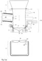
- FIG. 1 A sectional view of a mounting arrangement according to the invention is shown schematically.
- the mounting arrangement 10 comprises a first tubular element 11, to which a second tubular element 12 is connected, separated from the first tubular element by an annular gap 13.
- the first tubular element 11 and the second tubular element 12 surround an interior space 14.
- a first clamping element 15 extends radially outwardly around the first tubular element.
- the first tubular element, the second tubular element and the first clamping element are designed such that in the position shown in dashed lines, a film tube 20 can be held in the manner shown.
- the film tube can be guided from the interior through the annular gap to an outer side of the first tubular element, the film tube can be guided along a first circumferential line 20' of the film tube through the first
- the clamping element can be sealed, and the film tube can be sealed in the annular gap along a second 20" circumferential line of the film tube.
- the two circumferential lines appear as dots.
- FIG 2 the mounting arrangement is made of Figure 1 shown in a specific application.
- Process material 22 here in the form of pellets, is transferred from top to bottom in the direction of the arrow.
- the resulting fine dust 23 should not escape into the environment 24.
- a film tube 20 is held in the gap 13 and in a sealing manner by the first clamping element 15.
- the film tube In the direction of movement 27 of the first clamping element 15, symbolized by the horizontal double arrow, the film tube is pressed against the first contact surface 16 of the first tube element.
- the second tube element In the axial direction of movement 28 of the second tube element, the second tube element is moved towards the first tube element until the gap 13 is largely closed.
- the first and second tube elements are rotationally symmetrical with respect to the common axis 25.
- the spatial region 26 is now separated from the environment 24 of the holding arrangement by the film tube 20.
- Means 21 for generating a gas pressure in the aforementioned space 26 that is higher than the interior are implemented here, for example, by a compressed gas cylinder. Gas flows from the compressed gas cylinder through the gas outlet 18 into the space 26, which is arranged annularly around the first pipe element. Where a small gap opens along the gap 13, gas flows directly from the outside to the inside due to the overpressure compared to the interior 14, as symbolized by the double-lined arrows. The escape of even the finest particles of the process material into the environment is thus greatly reduced, even in the case of an imperfectly sealed gap between the film tube 20 and the first pipe element. As indicated by the dashed lines, the first pipe element can extend further upwards and, for example, be an element of a more complex transfer device.
- the interior space may have a gas outlet provided with a filter to the environment.
- a pressure difference between the pressure at the gas inlet and the interior space can be easily maintained, even if gas continuously flows through the gap 13 from the outside to the inside.
- Figure 3.a) Device construction First phase - end of a transfer process
- the embodiment shown here assumes that a process material, in the form of flowable solids, is transferred from the first container A into a second container B by means of the transfer device 100 in a contamination-protected manner.
- the first container A is directly connected in a sealed manner to a connection means 113 of the first pipe element 11 of the transfer device 100.
- the first pipe element functions as a guide tube.
- the first container A is, for example, a container or a component of a production plant.
- the second container B has, for example, the shape of a big bag or a container which contains a liner piece 108" as a bag-shaped inner liner, the free end 80" of which is usually provided with a closure 89 before the start of a transfer process.
- the conveying direction could alternatively run from the second container B to the first container A.
- the An axial passage extending through the guide tube 11 allows the flow of the process material.
- the first tube element 11 terminates with a tube edge.
- An inert gas line 118 leads to the first tube element 11 in the form of a guide tube, for supplying inert gas if required by the specific process material, and a detergent line 119 for cleaning the device 100.
- a transfer unit 116 opens into the first tube element 11, which allows engagement with the tube element and on which a plurality of removable useful sections 70, each provided with a first crimp 71, are stored from a tubular liner supply 107.
- the current useful section 70 lies in the transfer unit 116 until its use, with its first crimp 71 facing the mouth. It is pushed toward the mouth by a plug 166, which can be inserted into the transfer unit 116 from the outside.
- the plug 166 can be pulled out of the transfer unit 116 and connected to a cover 165 that can be attached to it.
- the transfer unit 116 is designed in the form of a side nozzle extending from the first tubular element 11 and opens at a gradient with a through opening into the wall of the first tubular element 11.
- a liner residue 108' from a previous transfer process is held in this state in a sealing manner in three areas, namely in the annular gap 13 between the first 11 and second 12 Pipe element, in the first clamping element 15 and in the second clamping element 101.
- the first and second clamping elements run in a ring around the first pipe element. They are shown in the cross-sectional drawing Fig. 3.a ) cut in two places each.
- the liner remnant 108' extends under the tube edge of the first tube element 11, traversing the annular gap 13 and, provided with the closing second crimp 81' at the bottom, hangs in a sack-like manner in the axial passage of the second tube element 12, which functions as a pressing unit.
- a base part 170 of the pressing unit is firmly connected to a lifting rod 150 (see Figure 3.b ), on which a pressed part 172 is elastically supported by means of an adjustable spring 171.
- the second tubular element 12 further has an activatable plugging element 173, which serves to crimp the free end 80 of a new liner piece 108 into the second clamping element 101. In the current phase, the plugging element 173 is in the retracted position, thus not acting on the second clamping element.
- the liner remnant 108' is pressed tightly against the tube edge of the first pipe element by the seal 174 arranged on the pressing part 172.
- the spring 171 is compressed, and thus the compressive force exerted via the lifting rod also acts on the seal 174.
- the second clamping element 101 remains activated, and the second tubular element (i.e., the pressing unit) has moved away from the first tubular element 11 (i.e., from the guide tube).
- the spring 171 has been maximally relaxed, so the pressing ring 172 slides out of the base part 170.
- the first clamping element 15 is now released. This allows the remaining end 80' of the liner remnant 108', which was previously clamped there, to be pulled out and now hangs freely.
- the remaining end 80' and the new liner piece 108 are guided around the tube edge.
- the base part 170 of the second tube element has been moved up to a clamping position against the first tube element 11, so that the seal 174 arranged on the pressing part 172 now presses the remaining end 80' and the new liner piece 108 only moderately against the tube edge due to the force of the spring 171.
- the second clamping element 101 can now be released, while the first clamping element 15 remains firmly closed.
- the cover 165, together with the plug 166, are removed from the transfer unit 116.
- the liner remnant 108' is gripped by the useful section 70 currently advanced from the liner supply 107 into the guide tube, i.e., into the first tube element 11.
- the gripped liner remainder 108' While maintaining the position of the second pipe element 12, which functions as a pressing unit, the gripped liner remainder 108', including the second crimp 81', is pulled out of the released second clamping element 101 and out of the clamping point formed by the annular gap 13 by means of the useful section 70, with only moderate contact pressure of the seal 174 on the clamping point against the tube edge, and is pulled into the transfer unit 116.
- the useful section 70, with the first crimp 71 present thereon, thus begins to emerge from the transfer unit 116.
- the first clamping element 15 remains closed, so that the clamped end 80 of the new liner piece 108 remains firmly sealed and is under no circumstances pulled out.
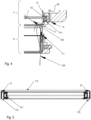
- the gas outlet opens from an area between the annular gap and the aforementioned contact surface on the outer surface of the first tubular element.
- the gas outlet is in direct fluid-dynamic communication with the outer edge of the annular gap via the annular channel 41.
- FIG. 5 An exemplary embodiment of the second clamping element 101 is shown, which is designed as an inflatable seal.
- the annular channel 41 is designed as a groove surrounding the first tubular element 11.
- a gas for example air or an inert gas, flows into the annular channel through at least one access channel 176, preferably 6 to 8 access channels (arrow 177).
- a hose for example, which supplies the gas, can be connected to the access channel 176 (see Figure 6 ).
- a guide lip 175 forms an air gap 42 between the annular channel 41 and the Inflatable seal.
- the number and arrangement of the access channels 176 can be selected to achieve the most homogeneous pressure distribution of the gas in the annular channel.
- the number and arrangement of the access channels can ensure a homogeneous pressure distribution if the gas escapes unevenly via the air gap, e.g. past the inflatable seal.
- the guide lip can be made of plastic and/or removably attached to the second clamping element. The function of the gas to prevent dust escape is described above for the Figure 4 described.
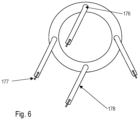
- FIG. 6 shows a bottom view of the second clamping element 101 from Figure 5
- hoses or pipes 178 are attached to the access channels 176, through which the gas (arrow 177), for example, air or an inert gas, flows into the access channels.
- the gas for example, air or an inert gas
- Four access channels are shown, but this number is only exemplary, and at least one access channel, but preferably 6 to 8 access channels, can be attached.
Landscapes
- Engineering & Computer Science (AREA)
- Mechanical Engineering (AREA)
- Chemical & Material Sciences (AREA)
- Dispersion Chemistry (AREA)
- Manipulator (AREA)
- Pipe Accessories (AREA)
Applications Claiming Priority (1)
| Application Number | Priority Date | Filing Date | Title |
|---|---|---|---|
| CH000885/2023A CH721047A2 (de) | 2023-08-22 | 2023-08-22 | Halterungs-anordnung zum dichten haltern eines folienschlauches und umfüllvorrichtung umfassend die halterungs-anordnung |
Publications (1)
| Publication Number | Publication Date |
|---|---|
| EP4534422A1 true EP4534422A1 (fr) | 2025-04-09 |
Family
ID=94690166
Family Applications (1)
| Application Number | Title | Priority Date | Filing Date |
|---|---|---|---|
| EP24193616.0A Pending EP4534422A1 (fr) | 2023-08-22 | 2024-08-08 | Ensemble de retenue pour dispositif de transvasement |
Country Status (3)
| Country | Link |
|---|---|
| US (1) | US12466655B2 (fr) |
| EP (1) | EP4534422A1 (fr) |
| CH (1) | CH721047A2 (fr) |
Citations (3)
| Publication number | Priority date | Publication date | Assignee | Title |
|---|---|---|---|---|
| EP3718911A1 (fr) | 2019-04-05 | 2020-10-07 | Rubitec AG | Dispositif de transvasement permettant de transférer de manière protégée contre la contamination d'un matériau de processus coulant entre un premier et un second récipients |
| EP3725694A1 (fr) * | 2019-04-18 | 2020-10-21 | J. Engelsmann AG | Dispositif pour vider des matières en vrac d'un récipient dans un récipient en pente |
| EP4046926A1 (fr) * | 2021-02-18 | 2022-08-24 | J. Engelsmann AG | Dispositif de remplissage de matières en vrac d'un récipient dans un sac de récipient |
Family Cites Families (2)
| Publication number | Priority date | Publication date | Assignee | Title |
|---|---|---|---|---|
| US4344468A (en) * | 1979-06-06 | 1982-08-17 | E. I. Du Pont De Nemours And Company | Process and apparatus for packaging |
| DE102004005961B4 (de) * | 2003-12-11 | 2005-11-24 | Hecht Anlagenbau Gmbh | Verfahren zur kontaminationsvermeidenden Entleerung bzw. Befüllung von Schüttgutbehältern |
-
2023
- 2023-08-22 CH CH000885/2023A patent/CH721047A2/de unknown
-
2024
- 2024-08-08 EP EP24193616.0A patent/EP4534422A1/fr active Pending
- 2024-08-21 US US18/811,596 patent/US12466655B2/en active Active
Patent Citations (3)
| Publication number | Priority date | Publication date | Assignee | Title |
|---|---|---|---|---|
| EP3718911A1 (fr) | 2019-04-05 | 2020-10-07 | Rubitec AG | Dispositif de transvasement permettant de transférer de manière protégée contre la contamination d'un matériau de processus coulant entre un premier et un second récipients |
| EP3725694A1 (fr) * | 2019-04-18 | 2020-10-21 | J. Engelsmann AG | Dispositif pour vider des matières en vrac d'un récipient dans un récipient en pente |
| EP4046926A1 (fr) * | 2021-02-18 | 2022-08-24 | J. Engelsmann AG | Dispositif de remplissage de matières en vrac d'un récipient dans un sac de récipient |
Also Published As
| Publication number | Publication date |
|---|---|
| CH721047A2 (de) | 2025-02-28 |
| US12466655B2 (en) | 2025-11-11 |
| US20250066127A1 (en) | 2025-02-27 |
Similar Documents
| Publication | Publication Date | Title |
|---|---|---|
| DE69404757T2 (de) | Mehrstufige hydroplastische Verformung doppelwandiger Rohre | |
| EP3041749B1 (fr) | Dispositif de transvasement de matière de processus entre un premier et un deuxième récipient et procédé correspondant | |
| DE69313414T2 (de) | Einsetzbarer barrieresack oder schicht für einen ausgabebehälter mit engem hals und verfahren zum füllen eines solchen papiersackes oder einer solchen schicht durch ein siphonrohr | |
| DE2805032C2 (de) | Röhrenfilterpresse | |
| EP2495173B1 (fr) | Dispositif et procédé de remplissage de sacs d'aération avec des marchandises coulantes | |
| EP0555740A1 (fr) | Installation de filtrage | |
| EP4046926B1 (fr) | Dispositif de remplissage de matières en vrac d'un récipient dans un sac de récipient | |
| EP0680897B1 (fr) | Dispositif de vidage pour conteneurs pour matériaux en vrac | |
| EP4095051A1 (fr) | Procédé et dispositif de vidange protégée contre la contamination d'un récipient | |
| EP3718911B1 (fr) | Dispositif de transvasement permettant de transférer de manière protégée contre la contamination d'un matériau de processus coulant entre un premier et un second récipients | |
| EP4046927B1 (fr) | Procédé pour vider un sac de conteneur | |
| EP4534422A1 (fr) | Ensemble de retenue pour dispositif de transvasement | |
| WO2010145042A1 (fr) | Dispositif permettant de décharger un produit de transfert d'un confinement et procédé à cet effet | |
| DE102017212510A1 (de) | Anschlussvorrichtung | |
| DE102011086278A1 (de) | Entleerverfahren und Entleervorrichtung für ein kontaminationsfreies Entleeren eines zumindest teilweise flexiblen Gebindes | |
| EP3722216B1 (fr) | Procédé et dispositif de remplissage et / ou de vidange de récipients souples | |
| WO2019110637A1 (fr) | Procédé et outil de mise en place pour insérer un piston dans un récipient | |
| DE69501107T2 (de) | Füllkopf | |
| DE69405236T2 (de) | Vorrichtung zum herstellen von knochenzement | |
| EP4530247A1 (fr) | Dispositif avec plaque d'essuyage pour un récipient de stockage de matériau et appareil de déchargement avec ledit dispositif | |
| EP1043074A1 (fr) | Appareil de dégraissage de pièces de série | |
| EP3137396B1 (fr) | Système de fermeture, procédé permettant de fermer une fermeture et conteneur de produits en vrac avec un tel système | |
| EP4367042A1 (fr) | Dispositif de protection, ensemble de protection pour récipient et procédé de raccordement d'un dispositif de protection à un récipient | |
| DE102008001752A1 (de) | Befüllungsvorrichtung und Verfahren zum Befüllen von Behältern | |
| EP3127826B1 (fr) | Buse destinée à gonfler un sachet à bec verseur en film et procédé de gonflage d'un sachet à bec verseur en film |
Legal Events
| Date | Code | Title | Description |
|---|---|---|---|
| PUAI | Public reference made under article 153(3) epc to a published international application that has entered the european phase |
Free format text: ORIGINAL CODE: 0009012 |
|
| STAA | Information on the status of an ep patent application or granted ep patent |
Free format text: STATUS: THE APPLICATION HAS BEEN PUBLISHED |
|
| AK | Designated contracting states |
Kind code of ref document: A1 Designated state(s): AL AT BE BG CH CY CZ DE DK EE ES FI FR GB GR HR HU IE IS IT LI LT LU LV MC ME MK MT NL NO PL PT RO RS SE SI SK SM TR |
|
| STAA | Information on the status of an ep patent application or granted ep patent |
Free format text: STATUS: REQUEST FOR EXAMINATION WAS MADE |
|
| 17P | Request for examination filed |
Effective date: 20250722 |