EP4534701A1 - Elektroofen - Google Patents
Elektroofen Download PDFInfo
- Publication number
- EP4534701A1 EP4534701A1 EP22945037.4A EP22945037A EP4534701A1 EP 4534701 A1 EP4534701 A1 EP 4534701A1 EP 22945037 A EP22945037 A EP 22945037A EP 4534701 A1 EP4534701 A1 EP 4534701A1
- Authority
- EP
- European Patent Office
- Prior art keywords
- melting furnace
- furnace
- cell
- electrode
- space
- Prior art date
- Legal status (The legal status is an assumption and is not a legal conclusion. Google has not performed a legal analysis and makes no representation as to the accuracy of the status listed.)
- Pending
Links
Images




Classifications
-
- C—CHEMISTRY; METALLURGY
- C21—METALLURGY OF IRON
- C21C—PROCESSING OF PIG-IRON, e.g. REFINING, MANUFACTURE OF WROUGHT-IRON OR STEEL; TREATMENT IN MOLTEN STATE OF FERROUS ALLOYS
- C21C5/00—Manufacture of carbon-steel, e.g. plain mild steel, medium carbon steel or cast steel or stainless steel
- C21C5/52—Manufacture of steel in electric furnaces
- C21C5/5252—Manufacture of steel in electric furnaces in an electrically heated multi-chamber furnace, a combination of electric furnaces or an electric furnace arranged for associated working with a non electric furnace
-
- F—MECHANICAL ENGINEERING; LIGHTING; HEATING; WEAPONS; BLASTING
- F27—FURNACES; KILNS; OVENS; RETORTS
- F27B—FURNACES, KILNS, OVENS OR RETORTS IN GENERAL; OPEN SINTERING OR LIKE APPARATUS
- F27B3/00—Hearth-type furnaces, e.g. of reverberatory type; Electric arc furnaces ; Tank furnaces
- F27B3/04—Hearth-type furnaces, e.g. of reverberatory type; Electric arc furnaces ; Tank furnaces of multiple-hearth type; of multiple-chamber type; Combinations of hearth-type furnaces
- F27B3/045—Multiple chambers, e.g. one of which is used for charging
-
- C—CHEMISTRY; METALLURGY
- C21—METALLURGY OF IRON
- C21B—MANUFACTURE OF IRON OR STEEL
- C21B11/00—Making pig-iron other than in blast furnaces
- C21B11/10—Making pig-iron other than in blast furnaces in electric furnaces
-
- C—CHEMISTRY; METALLURGY
- C21—METALLURGY OF IRON
- C21B—MANUFACTURE OF IRON OR STEEL
- C21B13/00—Making spongy iron or liquid steel, by direct processes
- C21B13/12—Making spongy iron or liquid steel, by direct processes in electric furnaces
-
- C—CHEMISTRY; METALLURGY
- C21—METALLURGY OF IRON
- C21B—MANUFACTURE OF IRON OR STEEL
- C21B13/00—Making spongy iron or liquid steel, by direct processes
- C21B13/14—Multi-stage processes processes carried out in different vessels or furnaces
-
- C—CHEMISTRY; METALLURGY
- C21—METALLURGY OF IRON
- C21C—PROCESSING OF PIG-IRON, e.g. REFINING, MANUFACTURE OF WROUGHT-IRON OR STEEL; TREATMENT IN MOLTEN STATE OF FERROUS ALLOYS
- C21C5/00—Manufacture of carbon-steel, e.g. plain mild steel, medium carbon steel or cast steel or stainless steel
- C21C5/56—Manufacture of steel by other methods
- C21C5/562—Manufacture of steel by other methods starting from scrap
-
- F—MECHANICAL ENGINEERING; LIGHTING; HEATING; WEAPONS; BLASTING
- F27—FURNACES; KILNS; OVENS; RETORTS
- F27B—FURNACES, KILNS, OVENS OR RETORTS IN GENERAL; OPEN SINTERING OR LIKE APPARATUS
- F27B14/00—Crucible or pot furnaces
-
- F—MECHANICAL ENGINEERING; LIGHTING; HEATING; WEAPONS; BLASTING
- F27—FURNACES; KILNS; OVENS; RETORTS
- F27B—FURNACES, KILNS, OVENS OR RETORTS IN GENERAL; OPEN SINTERING OR LIKE APPARATUS
- F27B14/00—Crucible or pot furnaces
- F27B14/06—Crucible or pot furnaces heated electrically, e.g. induction crucible furnaces with or without any other source of heat
-
- F—MECHANICAL ENGINEERING; LIGHTING; HEATING; WEAPONS; BLASTING
- F27—FURNACES; KILNS; OVENS; RETORTS
- F27B—FURNACES, KILNS, OVENS OR RETORTS IN GENERAL; OPEN SINTERING OR LIKE APPARATUS
- F27B19/00—Combinations of different kinds of furnaces that are not all covered by any single one of main groups F27B1/00 - F27B17/00
- F27B19/02—Combinations of different kinds of furnaces that are not all covered by any single one of main groups F27B1/00 - F27B17/00 combined in one structure
-
- F—MECHANICAL ENGINEERING; LIGHTING; HEATING; WEAPONS; BLASTING
- F27—FURNACES; KILNS; OVENS; RETORTS
- F27B—FURNACES, KILNS, OVENS OR RETORTS IN GENERAL; OPEN SINTERING OR LIKE APPARATUS
- F27B3/00—Hearth-type furnaces, e.g. of reverberatory type; Electric arc furnaces ; Tank furnaces
- F27B3/04—Hearth-type furnaces, e.g. of reverberatory type; Electric arc furnaces ; Tank furnaces of multiple-hearth type; of multiple-chamber type; Combinations of hearth-type furnaces
-
- F—MECHANICAL ENGINEERING; LIGHTING; HEATING; WEAPONS; BLASTING
- F27—FURNACES; KILNS; OVENS; RETORTS
- F27B—FURNACES, KILNS, OVENS OR RETORTS IN GENERAL; OPEN SINTERING OR LIKE APPARATUS
- F27B3/00—Hearth-type furnaces, e.g. of reverberatory type; Electric arc furnaces ; Tank furnaces
- F27B3/08—Hearth-type furnaces, e.g. of reverberatory type; Electric arc furnaces ; Tank furnaces heated electrically, with or without any other source of heat
- F27B3/085—Arc furnaces
-
- F—MECHANICAL ENGINEERING; LIGHTING; HEATING; WEAPONS; BLASTING
- F27—FURNACES; KILNS; OVENS; RETORTS
- F27B—FURNACES, KILNS, OVENS OR RETORTS IN GENERAL; OPEN SINTERING OR LIKE APPARATUS
- F27B3/00—Hearth-type furnaces, e.g. of reverberatory type; Electric arc furnaces ; Tank furnaces
- F27B3/10—Details, accessories or equipment, e.g. dust-collectors, specially adapted for hearth-type furnaces
- F27B3/105—Slag chamber
-
- F—MECHANICAL ENGINEERING; LIGHTING; HEATING; WEAPONS; BLASTING
- F27—FURNACES; KILNS; OVENS; RETORTS
- F27B—FURNACES, KILNS, OVENS OR RETORTS IN GENERAL; OPEN SINTERING OR LIKE APPARATUS
- F27B3/00—Hearth-type furnaces, e.g. of reverberatory type; Electric arc furnaces ; Tank furnaces
- F27B3/10—Details, accessories or equipment, e.g. dust-collectors, specially adapted for hearth-type furnaces
- F27B3/22—Arrangements of air or gas supply devices
-
- F—MECHANICAL ENGINEERING; LIGHTING; HEATING; WEAPONS; BLASTING
- F27—FURNACES; KILNS; OVENS; RETORTS
- F27D—DETAILS OR ACCESSORIES OF FURNACES, KILNS, OVENS OR RETORTS, IN SO FAR AS THEY ARE OF KINDS OCCURRING IN MORE THAN ONE KIND OF FURNACE
- F27D1/00—Casings; Linings; Walls; Roofs
-
- F—MECHANICAL ENGINEERING; LIGHTING; HEATING; WEAPONS; BLASTING
- F27—FURNACES; KILNS; OVENS; RETORTS
- F27D—DETAILS OR ACCESSORIES OF FURNACES, KILNS, OVENS OR RETORTS, IN SO FAR AS THEY ARE OF KINDS OCCURRING IN MORE THAN ONE KIND OF FURNACE
- F27D3/00—Charging; Discharging; Manipulation of charge
- F27D3/0025—Charging or loading melting furnaces with material in the solid state
-
- H—ELECTRICITY
- H05—ELECTRIC TECHNIQUES NOT OTHERWISE PROVIDED FOR
- H05B—ELECTRIC HEATING; ELECTRIC LIGHT SOURCES NOT OTHERWISE PROVIDED FOR; CIRCUIT ARRANGEMENTS FOR ELECTRIC LIGHT SOURCES, IN GENERAL
- H05B7/00—Heating by electric discharge
- H05B7/18—Heating by arc discharge
- H05B7/20—Direct heating by arc discharge, i.e. where at least one end of the arc directly acts on the material to be heated, including additional resistance heating by arc current flowing through the material to be heated
-
- F—MECHANICAL ENGINEERING; LIGHTING; HEATING; WEAPONS; BLASTING
- F27—FURNACES; KILNS; OVENS; RETORTS
- F27D—DETAILS OR ACCESSORIES OF FURNACES, KILNS, OVENS OR RETORTS, IN SO FAR AS THEY ARE OF KINDS OCCURRING IN MORE THAN ONE KIND OF FURNACE
- F27D3/00—Charging; Discharging; Manipulation of charge
- F27D2003/0034—Means for moving, conveying, transporting the charge in the furnace or in the charging facilities
- F27D2003/0062—Means for moving, conveying, transporting the charge in the furnace or in the charging facilities using devices for tilting or rocking the charge
-
- Y—GENERAL TAGGING OF NEW TECHNOLOGICAL DEVELOPMENTS; GENERAL TAGGING OF CROSS-SECTIONAL TECHNOLOGIES SPANNING OVER SEVERAL SECTIONS OF THE IPC; TECHNICAL SUBJECTS COVERED BY FORMER USPC CROSS-REFERENCE ART COLLECTIONS [XRACs] AND DIGESTS
- Y02—TECHNOLOGIES OR APPLICATIONS FOR MITIGATION OR ADAPTATION AGAINST CLIMATE CHANGE
- Y02P—CLIMATE CHANGE MITIGATION TECHNOLOGIES IN THE PRODUCTION OR PROCESSING OF GOODS
- Y02P10/00—Technologies related to metal processing
- Y02P10/20—Recycling
Definitions
- a steel material production process in steel metallurgy industries may be largely divided into a "blast furnace-converter” production system (hereinafter, referred to as “converter”) that uses ores as the main raw material, and an “electric furnace” production system that uses scraps recovered/recycled after manufacturing products by utilizing the produced steel material.
- a "blast furnace-converter” production system hereinafter, referred to as “converter”
- an “electric furnace” production system that uses scraps recovered/recycled after manufacturing products by utilizing the produced steel material.
- the above material is a raw material based on ores (the component similar to that used in the blast furnace), this has an advantage of controlling the initial property of molten steel (that is, an input level of Tramp elements) according to a mixing ratio when it is applied to the electric furnace.
- a mixing ratio when it is applied to the electric furnace.
- mass application high mixing ratio is applied: ⁇ 30%), it cannot be introduced through "Batching charging", a typical main raw material charging manner in the electric furnace, but entails a disadvantage in that a separate feeding installation such as "Continuous Roof Charging” is required.
- a scrap melting process susceptible to nitrogen inflow is shortened (becoming Flat Batch) thereby attaining effects of reducing [N] level in the molten steel.
- the reductive reaction is somewhat disadvantageous compared to the blast furnace process, and FeO content in raw material (5 to 8%) is generally high. Due to this, there is a problem in that a reduction process must be maximally performed (increase of energy and reductive agent consumption) in the electric furnace, in which an oxidation process is performed. Accordingly, as the mixing ratio increases, working performance or operation results such as increased use amount of slag former, increased power consumption, decreased molten steel recovery, reduction of productivity, etc., are drastically deteriorated and may result in loss of cost competitiveness.
- the present invention is for solving different problems including the above problems, and an object of the present invention is to provide an electric furnace that variably controls DRI/HBI (including other OBMs) mixing ratio from 0 to 100% depending on types of steels to be produced and, simultaneously, ensures working stability in response to high mixing ratio as well as economic advantage.
- DRI/HBI including other OBMs
- the first upper cell may have a furnace wall formed of a refractory material so that the melting furnace has a fire-resisting structure.
- the first electrode member may include a plurality of alternate current (AC) electrodes that are radially disposed around the center of the small ceiling of the first roof part, while the plurality of iron source feeders may continuously feed the first iron source, respectively, toward ignition points of individual AC electrodes corresponding to individual iron source feeders.
- AC alternate current
- the lower DC electrode may include a first lower electrode, in which a central axis is formed to be coaxial with a central axis of the upper DC electrode on the bottom of the lower cell, so that the lower DC electrode can directly face with the upper DC electrode.
- the lower DC electrode may further include a second lower electrode, in which a central axis is formed to be inclined at a predetermined angle to the central axis of the upper DC electrode on the bottom of the lower cell and thus to be biased toward the pre-heat feeder with respect to the upper DC electrode, so that the lower DC electrode can face with the upper DC electrode in an inclined direction.
- the second electrode member may induce a current flow between the upper DC electrode and the second lower electrode immediately after feeding the second iron source by the pre-heat feeder, while inducing a current flow between the upper DC electrode and the first lower electrode after the second iron source is completely molten.
- the electric furnace of the present invention may further include an exhaust gas duct that connects the first upper cell and the second upper cell in a duct form and feeds waste heat generated in the first melting furnace toward the second melting furnace.
- the first melting furnace may include a first slag door, which is provided at a boundary portion between the first upper cell and the lower cell and is configured in a double door form that includes an upper door opening upward and a lower door opening downward to face each other in the vertical direction, so that the slag generated in the first melting furnace can be selectively excluded.
- a first slag door which is provided at a boundary portion between the first upper cell and the lower cell and is configured in a double door form that includes an upper door opening upward and a lower door opening downward to face each other in the vertical direction, so that the slag generated in the first melting furnace can be selectively excluded.
- the first melting furnace may open the upper door to maintain a height of the slag in the first melting furnace at a predetermined level during operation, while opening the lower door when excluding (or discharging) the slag inside the first melting furnace.
- the lower cell may be provided with a tapping port on a floor surface forming the first lower space at a position corresponding to the first electrode member, which is installed on the small ceiling of the first roof part formed on top of the first upper cell, so as to tap the molten metal in the double type melting furnace.
- the floor surface forming the first lower space, in which the tapping port is formed, in the lower cell may be higher than a floor surface forming the second lower space.
- the electric furnace of the present invention may further include a tilting device that can tilt the double type melting furnace, in which the first melting furnace and the second melting furnace are at least partially combined, in the horizontal direction or enables double tilting of the same in the horizontal direction and a width direction perpendicular to the vertical direction.
- a tilting device that can tilt the double type melting furnace, in which the first melting furnace and the second melting furnace are at least partially combined, in the horizontal direction or enables double tilting of the same in the horizontal direction and a width direction perpendicular to the vertical direction.
- the tilting device may include: in order to maintain the center of the double type melting furnace tilted by the tilting device, a support cylinder that supports the double type melting furnace while possibly tilting the same; and a plurality of drive cylinders, specifically, at least three drive cylinders that are radially disposed around the support cylinder to support the double type melting furnace on at least three points, and can be separately driven up and down in order to selectively tilt the double type melting furnace in the horizontal direction or the width direction described above.
- the pre-heat feeder may include: a pre-heat chamber that is formed in a cylindrical shape or a polygonal column shape to be extended in the vertical direction, thereby configuring a finger type shaft furnace; and a chamber door that is installed on a lower side of the opened pre-heat chamber in order to selectively open the lower side of the pre-heat chamber.
- the first iron source introduced into the first melting furnace may include ore-based materials (OBM's), while the second iron source introduced into the second melting furnace may include scraps.
- OBM's ore-based materials
- this basically involves concurrent introduction of OBM's and low-grained scraps, as well as general scraps, and gangue components input in large quantities from OBMs may be effectively separated to prevent the same from being mixed with the existing slag (the gangue comprising SiO 2 and Al 2 O 3 as main components mostly acts as an acidic slag and, if the input amount is large, may become a reason for introducing a large amount of CaO in order to refine/remove P component in the molten steel, therefore, an increase in unit of slag former source and a large amount of slag generated due to the same may act major factors for non-economical structure such as reduction of molten steel recovery, increased energy consumption, extended operation time, etc.), whereby a double type melting furnace capable of melting the main raw material and refining simultaneously can be implemented.
- the present invention relates to a new concept of melting method using an electric furnace that introduces a large amount of ore-based iron source (representative by DRI) and, simultaneously, can ensure the same or higher productivity/economical advantage/quality than the conventional "blast furnace-converter” production system, wherein a new form of electric furnace capable of using OBM's in large quantities is used to thus achieve effects of realizing carbon neutral in steel-making industry.
- influence of gangue input in large quantities from DRI on working as well as optimum refining conditions may be maintained/managed by effectively separating and discharging the gangue from the first melting furnace; mass application of DRI utilizing the first melting furnace for OBM's only with high efficiency is possible to thus decrease Tramp components; according to a process of scrap introduction/operation through the first melting furnace, to which OBM's are continuously charged, and the second melting furnace connected to the same in the form of double structure, a perfect Flat Bath operation may be performed; and nitrogen pick-up may be effectively blocked through arc sealing owing to an exhaust gas duct structure, thereby ensuring N output level of the converter.
- the electric furnace 1000 may be an electric furnace provided with a double type melting furnace F in which two melting furnaces 10 and 20 are disposed in a horizontal direction (X-axial direction) and are at least partially combined, so as to melt different iron sources.
- the first iron source 1 is not stacked in the furnace and the furnace does not need a large space. Therefore, an internal volume of the furnace may be limited to a minimum level sufficient not to damage an external wall due to arc generated in the electrode (that is, a compact type furnace having a smaller volume compared to a second melting furnace 20 described later), so that it has a structure capable of concentrating the applied energy to thus induce high melting rate.
- the first melting furnace 10 and the second melting furnace 20 to configure the double type melting furnace F are provided in a double furnace structure in which both of these furnaces are at least partially combined to form a single body sharing a lower cell 300, in addition, high efficiency supplementary equipment to apply chemical energy and control a reaction in the furnace may further be provided and operated (additional or secondary raw material and a gas injector, or the like; since types and locations of the equipment are freely operated as necessary according to the concept of process design, a detailed description thereof will be omitted in the present invention).
- first upper cell 100 a first upper cell 100, a second upper cell 200, a lower cell 300 and a partition wall unit 400, which configure the first melting furnace 10 and the second melting furnace 20 in the above described double type melting furnace F.
- the first melting furnace 100 is made of a refractory material and may form a first upper space (A1-1) of the first melting furnace 10 in which the first iron source 1 is introduced and molten therein.
- a minimum water cooling installation may be provided (an outer shell water cooling structure is not shown in FIG. 1 ).
- the first upper cell 100 may include: a first electrode member 110, of which at least a portion is inserted into the first upper space (A1-1) of the first melting furnace 10 through a small ceiling of a first roof part 100a formed on top of the first upper cell 100 and melts the first iron source 1 with arc heat; and a plurality of iron source feeders 120 that are radially disposed around the center of the first electrode member 110 and feeds the first iron source 1 through the first upper space (A1-1) of the first melting furnace 10.
- the first electrode member 110 consisting of the plural AC electrodes (111, 112, 113) (if necessary, a direct current (DC) current flowing system may also be introduced) is characterized in that OBM's having a relatively low specific gravity than molten steel, which is introduced as the first iron source 1 into the first melting furnace 10, may exist in slag 4a or on an interface between molten metal 3 and the slag 4a, therefore, it may be effective to form a wide ignition point. Moreover, at the beginning of the operation, for arc protection and prevention of nitrogen pickup by arc, slag 4a foaming is required.
- the AC current flowing system may be more advantageous.
- the plural iron source feeders 120 are an apparatus for continuously introducing OBM's as the first iron source 1 (if necessary, low-grained scraps may also be introduced). Although not shown, this may be the equipment that delivers the first iron source 1 to a conveyer from any storage facilities of the corresponding main raw material, allows the iron source to free fall into a pipe type shutter (transforming from potential energy to kinetic energy) through a transmission hopper mounted at a desired height on the top of the first melting furnace 10 to thus ensure sufficient kinetic energy, which in turn, continuously introduces the first iron source 1 into the furnace through a plurality of input ports provided to correspond to the plural AC electrodes (111, 112, 113), respectively. More particularly, the plural iron source feeders 120 may continuously introduce the first iron source 1 to three ignition points formed between the plural AC electrodes (111, 112, 113) of the first electrode member 110, thereby maximizing melting efficiency.
- the second upper cell 200 may be disposed in parallel to the first upper cell 100 in a horizontal direction (X-axial direction), and may form a second upper space (A2-1) of the second melting furnace 20 in which scraps are introduced and molten as a second iron source 2.
- the second iron source 2 may mostly include scraps and, in addition, some high-grained ore-based materials (OBM's).
- the second upper cell 200 of the second melting furnace 20 is fundamentally designed similar to the water cooling equipment in the common electric furnace, in addition, may be configured as a water cooling installation with a double-layer structure which is somewhat decreased in size and can effectively form a thick slag coating layer on the furnace wall for heat insulation, so that the second upper cell preferably becomes a system capable of separately controlling the cooling performance of each layer.
- the second electrode member 210 may include: an upper direct current (DC) electrode 211 that is inserted through the small ceiling of the second roof part 200a, and is provided on the second upper space (A2-1) side of the second melting furnace 20; a lower DC electrode 212 that is installed on the bottom of the lower cell 300 to face with the upper DC electrode 211 in the vertical direction, and is provided on the second lower space (A2-2) side of the second melting furnace 20.
- DC direct current
- the second electrode member 210 may be a DC electrode member, which is further provided with the second lower electrode 212b deflected toward the pre-heat feeder 220 with respect to the upper DC electrode 211.
- the second melting furnace 20 as an exclusive furnace for melting general scraps is principally not limited in terms of types of power supply system (AC or DC applicable), however, since the pre-heat feeder 220 is placed, it may entail a structural limitation in that, when the second iron source 2 is loaded, the second iron source 2 is introduced and lean too much toward the lower side of the pre-heat feeder 220 apart from the center of the second electrode member 210.
- selectively using both lower electrodes (212a, 212b) or varying a relative ratio thereof may control a flow of electric energy application to the second melting furnace 20 during processing, which in turn can induce effective melting work.
- an installation for introduction of a chemical energy as a supplementary energy is also possibly provided to the furnace wall at the lower side of the pre-heat feeder 220.
- the pre-heat feeder 220 may include: a pre-heat chamber 221 that is formed in a cylindrical shape or a polygonal column shape to be extended in the vertical direction, thereby configuring a finger type shaft furnace; and a chamber door 222 that is installed on a lower side of the opened pre-heat chamber 221 in order to selectively open the lower side of the pre-heat chamber 221 and thus to selectively feed the second iron source 2.
- the pre-heat feeder 220 adopted in the second melting furnace 20 of the present invention is a pre-heat furnace that utilizes the waste heat fed in the form of exhaust gas emitted to atmosphere without being used for production of molten metal among the energy applied to the inside of the furnace and can preheat the second iron source 2.
- a partition wall unit 400 described later divides mechanically the first upper space (A1-1) of the first melting furnace 10 and the second upper space (A2-1) of the second melting furnace 20
- the exhaust gas duct 500 may be mounted to connect the first upper space (A1-1) of the first melting furnace 10 and the second upper space (A2-1) of the second melting furnace 20, thereby ensuring a flow path of the waste heat generated in the first melting furnace 100.
- it may be configured in that an entrance at the second melting furnace 20 side for the exhaust gas fed from the first melting furnace 10 is located in the opposite direction of the pre-heat feeder 220, and the corresponding fluid stream passes through an arc generating site of the second melting furnace 20 and then is supplied to the pre-heat feeder 220, whereby a sealing function of blocking the arc generated in the second electrode member 210 from the atmosphere may also be performed.
- the tapping port 310 existing in the lower cell 300 was designed with a structure without undesirable Cold Zone by removing the protruding structure for tapping, which is typically present in the common electric furnace. Therefore, when determining a location of the tapping port 310, in order to supply sand fed for sealing after tapping, as shown in FIG. 3 , the tapping port may be placed at a site immediately below an inlet of any one among the plurality of AC electrodes (111, 112, 113) provided in the first electrode member 110, so that it may be configured to fill the lower cell with sand by moving a sand feeding tube down through the inlet of the AC electrode.
- a bottom gas blowing device provided with a plurality of plugs (600a, 600b, 600c, 600d, 600e, 600f, 600g) to discharge (or emit) gas may be disposed on the bottom of the lower cell 300.
- FIG. 3 illustrates an example of the bottom gas blowing device 600 which is provided with plugs (600a, 600b, 600c, 600d, 600e, 600f, 600g) arranged on the bottom of the lower cell 300.
- plugs 600a, 600b, 600c, 600d, 600e, 600f, 600g
- FIG. 3 illustrates an example of the bottom gas blowing device 600 which is provided with plugs (600a, 600b, 600c, 600d, 600e, 600f, 600g) arranged on the bottom of the lower cell 300.
- plugs 600a, 600b, 600c, 600d, 600e, 600f, 600g
- kinds of the gas introduced through the bottom gas blowing device 600 may include inert gas (Ar, N 2 ) for simple flow control ot fuel/raw materials (O 2 , Ch 4 , CO, etc.) for reaction and heat source supply, which can be selectively introduced.
- inert gas Ar, N 2
- ot fuel/raw materials O 2 , Ch 4 , CO, etc.
- a tilting device 700 capable of tilting the double type melting furnace F, in which the first melting furnace 10 and the second melting furnace 20 are at least partially combined, in a horizontal direction (X-axial direction, or capable of double-tilting the same in both of the horizontal direction and a width direction (Y-axial direction) perpendicular to a vertical direction (Z-axial direction) may be provided at a lower side of the lower cell 300.
- the support cylinder 710 of the tilting device 700 is a structure installed at the center of weight of the double type melting furnace F, which may include: a tilting part that is tiltable in the horizontal direction (X-axial direction) and the width direction (Y-axial direction) and supports the double type melting furnace F; and a cylinder part connected to the above tilting part to insert the structure into a support surface of the double type melting furnace F so that the cylinder can move only up and down without alternative driving force, thereby playing a role of holding or securing the position of the double type melting furnace F.
- the support cylinder 710 is a device required to satisfy a necessity of differing tapping and slag discharge directions from each other in order to implement structural features of the double type melting furnace F of the present invention.
- these may consist of total fourth (4) cylinders, including two at the first melting furnace side 10 and other two at the second melting furnace side 30, with respect to the support cylinder 710 holding the center of the double type melting furnace F, so as to preferably perform tilting in two directions of the double type melting furnace F (the horizontal direction (X-axial direction) and the width direction (Y-axial direction)).
- the first melting furnace 10 as an electric furnace for OBM's only and the second melting furnace 20 as a scrap exclusive electric furnace may be combined to form the double type melting furnace F, wherein OBM's-based slag 4a and the scrap-based slag 4b should be produced without being admixed together. Therefore, it may be necessary to adopt the partition wall unit 400 capable of differing the slag (4a, 4b) from each other in the double type melting furnace F.
- the partition wall unit 400 may be provided as a device for controlling separation/integration of the slag (4a, 4b) generated in detailed process steps.
- the partition wall unit 400 may be composed of a water cooling structure and a refractory material, and may be adjusted by a drive device moving up and down between the first melting furnace 10 and the second melting furnace 20.
- the above device may be substantially an important device to implement the double type melting furnace F of the present invention.
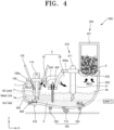
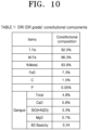
- the slag 4a generated in the first melting furnace 10 principally has different (constitutional) composition from that of the slag 4b generated in the second melting furnace 20 as a result of the general scrap work. Further, such a difference may be partially controlled and maintained if desired. Since a gangue component input from OBMs comprises acidic major components (SiO 2 , Al 2 O 3 ), low alkaline slag is formed and a large amount of FeO is contained. The input FeO must be maximally reduced and recovered by introducing C-based supplementary raw material thereto. Further, due to CO gas generated during the above process, the slag 4a may be subjected to foaming.
- the first slag door 11 may be configured in the form of multi-door, in which the door is provided in plural around the first melting furnace 10.
- a second slag door 21 of the second melting furnace 20 is a device having the same function as that of the existing and common electric furnace, and may be utilized to discharge the slag 4b of the furnace.
- the first slag door 11 mounted on the first melting furnace 10 is characterized in that the slag 4a generated in a large amount is continuously discharged to thus maintain a desirable level after taking a proper measure, while the second slag door 21 should be maintained in closed state except for a specific purpose, and has a structural form capable of driving in two directions (Y-axial direction, Z-axial direction) instead of an upward-opening structure in a simple water cooling panel form, which can be re-closed after opening during the operation.
- the partition wall unit 400 maximally descends and thus the first melting furnace 10 and the second melting furnace 20 are separated from each other, wherein the first melting furnace 10 may melt OBM's continuously introduced as the first iron source 1 through a plurality of iron source feeders 120, and the second melting furnace 20 may preheat scraps as the second iron source 2 inside the pre-heat feeder 220 through arcing while the slag 4b is kept under foaming, and may further apply the melting energy to the first melting furnace 10.
- a level of the molten metal 3 is raised (Level -> Level 2) by the melting process in the first melting furnace 10 and, if the raised level (Level 2) reaches a level completely submerged in the molten metal 3 when the second iron source 2 under preheating is introduced, a chamber door 222 is opened so as to charge the molten metal 3 with the preheated second iron source 2 in a pre-heat chamber 221.
- the preheated second iron source 2 is charged to thus attain effects of preventing nitrogen (N) pickup through arcing while ensuring a melting efficiency of the second iron source 2, that is, scraps, simultaneously.
- the partition wall unit 400 is completely raised and fully opened and, after excluding the slag 4a of the first melting furnace 10 (as a cause of decrease in refining performance) by upwardly opening the upper door 11a in the first slag door 11, final refining may be performed by admixing the molten metal with the slag 4b of the second melting furnace 20.
- refining efficiency may be maximized.
- the pre-heat feeder 200 may be configured in a separable form to the double type melting furnace F.
- a driving procedure of moving down and tilting a main body of the double type melting furnace F in a desired direction may be implemented.
- influence of gangue input in large quantities from DRI on working as well as optimum refining conditions may be maintained/managed by effectively separating and discharging the gangue from the first melting furnace; mass application of DRI utilizing the first melting furnace for OBM's only with high efficiency is possible to thus decrease Tramp components; according to a process of scrap introduction/operation through the first melting furnace, to which OBM's are continuously charged, and the second melting furnace connected to the same in the form of double structure, a perfect Flat Bath operation may be performed; and nitrogen pick-up may be effectively blocked through arc sealing owing to an exhaust gas duct structure, thereby ensuring N output level of the converter.
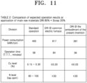
- a high energy concentrated structure of the first melting furnace, scrap preheating in the second melting furnace using exhaust gas, and the concurrent operation of the first melting furnace and the second melting furnace can reduce an energy consumption to a general scrap working level or less, and shorten an operation time to the converter level.
- an amount of power consumption was 617 kWh/ton for the common electric furnace.
- the expected operation index of the present invention it is expected to use 361 kWh/ton of power, demonstrating that the power consumption was decreased by about half compared to the common electric furnace.
- the operation time was about 84 minutes for the common electric furnace while taking about 39 minutes according to the expected operation result of the present invention, therefore, demonstrating that the operation time was also decreased by about half compared to the common electric furnace.
- Cu level and N level are 0.03% and 30 ppm, respectively, which are substantially similar to those of the converter and are possibly adjusted. Accordingly, the expected operation indexes of the present invention are predicted to be substantially the same or more excellent as compared to all scrap electric furnaces.
Landscapes
- Engineering & Computer Science (AREA)
- Chemical & Material Sciences (AREA)
- Mechanical Engineering (AREA)
- General Engineering & Computer Science (AREA)
- Organic Chemistry (AREA)
- Manufacturing & Machinery (AREA)
- Materials Engineering (AREA)
- Metallurgy (AREA)
- Plasma & Fusion (AREA)
- Physics & Mathematics (AREA)
- Vertical, Hearth, Or Arc Furnaces (AREA)
- Furnace Charging Or Discharging (AREA)
- Waste-Gas Treatment And Other Accessory Devices For Furnaces (AREA)
- Furnace Details (AREA)
Applications Claiming Priority (2)
| Application Number | Priority Date | Filing Date | Title |
|---|---|---|---|
| KR1020220068183A KR102736561B1 (ko) | 2022-06-03 | 2022-06-03 | 전기로 |
| PCT/KR2022/018984 WO2023234499A1 (ko) | 2022-06-03 | 2022-11-28 | 전기로 |
Publications (2)
| Publication Number | Publication Date |
|---|---|
| EP4534701A1 true EP4534701A1 (de) | 2025-04-09 |
| EP4534701A4 EP4534701A4 (de) | 2025-10-22 |
Family
ID=89025148
Family Applications (1)
| Application Number | Title | Priority Date | Filing Date |
|---|---|---|---|
| EP22945037.4A Pending EP4534701A4 (de) | 2022-06-03 | 2022-11-28 | Elektroofen |
Country Status (7)
| Country | Link |
|---|---|
| US (1) | US20250093100A1 (de) |
| EP (1) | EP4534701A4 (de) |
| JP (1) | JP2025517775A (de) |
| KR (1) | KR102736561B1 (de) |
| CN (1) | CN119343469A (de) |
| AU (1) | AU2022462002A1 (de) |
| WO (1) | WO2023234499A1 (de) |
Families Citing this family (2)
| Publication number | Priority date | Publication date | Assignee | Title |
|---|---|---|---|---|
| KR20260003929A (ko) * | 2024-07-01 | 2026-01-08 | 주식회사 포스코 | 강 제조방법 |
| CN121408982B (zh) * | 2025-12-25 | 2026-03-31 | 陕西中丰动力能源有限公司 | 一种锂电池负极材料碳化用石墨坩埚 |
Family Cites Families (13)
| Publication number | Priority date | Publication date | Assignee | Title |
|---|---|---|---|---|
| DE1433431B2 (de) * | 1963-10-29 | 1971-12-16 | Fried Krupp GmbH, 4300 Essen | Schmelzofen zur herstellung von stahl und verfahren zum betrieb des ofens |
| FR1601438A (de) * | 1968-10-17 | 1970-08-24 | ||
| AT384669B (de) * | 1986-03-17 | 1987-12-28 | Voest Alpine Ag | Anlage zur herstellung von stahl aus schrott |
| AT404841B (de) * | 1995-04-10 | 1999-03-25 | Voest Alpine Ind Anlagen | Anlage und verfahren zum herstellen von eisenschmelzen |
| JPH09105590A (ja) * | 1995-10-04 | 1997-04-22 | Daido Steel Co Ltd | アーク炉 |
| JPH1047860A (ja) * | 1996-05-27 | 1998-02-20 | Nkk Corp | 複式アーク溶解炉およびそれを用いた冷鉄源の溶解方法 |
| IT1289021B1 (it) * | 1996-11-13 | 1998-09-25 | Danieli Off Mecc | Forno elettrico ad arco e relativo procedimento di fusione continua |
| AT404942B (de) * | 1997-06-27 | 1999-03-25 | Voest Alpine Ind Anlagen | Anlage und verfahren zum herstellen von metallschmelzen |
| JP2008116066A (ja) * | 2006-10-31 | 2008-05-22 | Nisshin Steel Co Ltd | 電気炉の操業方法 |
| KR101185211B1 (ko) * | 2009-12-29 | 2012-09-21 | 현대제철 주식회사 | 전기로의 슬래그 배출 도어 장치 |
| KR101205054B1 (ko) * | 2012-06-28 | 2012-11-26 | 현대제철 주식회사 | 전기로 |
| KR101701648B1 (ko) * | 2015-11-24 | 2017-02-01 | 현대제철 주식회사 | 전기로를 이용한 용강 제조방법 |
| KR102556231B1 (ko) * | 2019-04-19 | 2023-07-18 | 닛폰세이테츠 가부시키가이샤 | 크롬 함유 용철의 제조 방법 |
-
2022
- 2022-06-03 KR KR1020220068183A patent/KR102736561B1/ko active Active
- 2022-11-28 AU AU2022462002A patent/AU2022462002A1/en active Pending
- 2022-11-28 CN CN202280096579.9A patent/CN119343469A/zh active Pending
- 2022-11-28 WO PCT/KR2022/018984 patent/WO2023234499A1/ko not_active Ceased
- 2022-11-28 EP EP22945037.4A patent/EP4534701A4/de active Pending
- 2022-11-28 JP JP2024568651A patent/JP2025517775A/ja active Pending
-
2024
- 2024-12-03 US US18/967,107 patent/US20250093100A1/en active Pending
Also Published As
| Publication number | Publication date |
|---|---|
| KR102736561B1 (ko) | 2024-12-02 |
| EP4534701A4 (de) | 2025-10-22 |
| AU2022462002A1 (en) | 2024-12-12 |
| JP2025517775A (ja) | 2025-06-10 |
| CN119343469A (zh) | 2025-01-21 |
| WO2023234499A1 (ko) | 2023-12-07 |
| KR20230167924A (ko) | 2023-12-12 |
| US20250093100A1 (en) | 2025-03-20 |
Similar Documents
| Publication | Publication Date | Title |
|---|---|---|
| US20250093100A1 (en) | Electric furnace | |
| KR100266826B1 (ko) | 용강을생산하는 설비와 방법 | |
| KR20000068375A (ko) | 용융금속을 생산하는 설비 및 방법 | |
| BG60921B2 (bg) | Метод и устройство за непрекъснато производство на стомана | |
| JPH0442452B2 (de) | ||
| GB2634170A (en) | Electric furnace | |
| KR102927395B1 (ko) | 용선 제조 방법 | |
| WO2023151242A1 (zh) | 一种金属熔炼装置及炼钢生产线 | |
| US20250383152A1 (en) | Method for operating electric furnace | |
| KR102628195B1 (ko) | 용강의 제조 방법 | |
| US11549156B2 (en) | Smelting assembly for the production of steel | |
| US4419128A (en) | Continuous melting, refining and casting process | |
| KR102777625B1 (ko) | 전기로 | |
| EP0843020B1 (de) | Doppel-Herd Elektro-Lichtbogenofen zum kontinuierlichen Schmelzen | |
| EP1660688B1 (de) | Verfahren zum chargieren von feinkörnigen materialien in einen elektrolichtbogenofen | |
| KR20250028427A (ko) | 전기 용융기 내에서의 철 용융물의 생산 방법 | |
| KR102829902B1 (ko) | 전기로 | |
| KR102751454B1 (ko) | 전기로 | |
| US4307872A (en) | Apparatus for reducing ore | |
| CN1154411A (zh) | 熔炼设备 | |
| CN222100101U (zh) | 钛渣冶炼装置 |
Legal Events
| Date | Code | Title | Description |
|---|---|---|---|
| STAA | Information on the status of an ep patent application or granted ep patent |
Free format text: STATUS: THE INTERNATIONAL PUBLICATION HAS BEEN MADE |
|
| PUAI | Public reference made under article 153(3) epc to a published international application that has entered the european phase |
Free format text: ORIGINAL CODE: 0009012 |
|
| STAA | Information on the status of an ep patent application or granted ep patent |
Free format text: STATUS: REQUEST FOR EXAMINATION WAS MADE |
|
| 17P | Request for examination filed |
Effective date: 20241126 |
|
| AK | Designated contracting states |
Kind code of ref document: A1 Designated state(s): AL AT BE BG CH CY CZ DE DK EE ES FI FR GB GR HR HU IE IS IT LI LT LU LV MC ME MK MT NL NO PL PT RO RS SE SI SK SM TR |
|
| DAV | Request for validation of the european patent (deleted) | ||
| DAX | Request for extension of the european patent (deleted) | ||
| A4 | Supplementary search report drawn up and despatched |
Effective date: 20250919 |
|
| RIC1 | Information provided on ipc code assigned before grant |
Ipc: C21B 13/12 20060101AFI20250915BHEP Ipc: C21B 13/14 20060101ALI20250915BHEP Ipc: F27B 3/04 20060101ALI20250915BHEP Ipc: F27B 3/08 20060101ALI20250915BHEP Ipc: F27B 19/02 20060101ALI20250915BHEP Ipc: C21B 11/10 20060101ALI20250915BHEP Ipc: C21C 5/56 20060101ALI20250915BHEP |