EP4534762A1 - Drehrahmen und arbeitsmaschine - Google Patents
Drehrahmen und arbeitsmaschine Download PDFInfo
- Publication number
- EP4534762A1 EP4534762A1 EP23201140.3A EP23201140A EP4534762A1 EP 4534762 A1 EP4534762 A1 EP 4534762A1 EP 23201140 A EP23201140 A EP 23201140A EP 4534762 A1 EP4534762 A1 EP 4534762A1
- Authority
- EP
- European Patent Office
- Prior art keywords
- revolving
- block
- support portion
- revolving frame
- work machine
- Prior art date
- Legal status (The legal status is an assumption and is not a legal conclusion. Google has not performed a legal analysis and makes no representation as to the accuracy of the status listed.)
- Pending
Links
Images


Classifications
-
- E—FIXED CONSTRUCTIONS
- E02—HYDRAULIC ENGINEERING; FOUNDATIONS; SOIL SHIFTING
- E02F—DREDGING; SOIL-SHIFTING
- E02F9/00—Component parts of dredgers or soil-shifting machines, not restricted to one of the kinds covered by groups E02F3/00 - E02F7/00
- E02F9/08—Superstructures; Supports for superstructures
- E02F9/10—Supports for movable superstructures mounted on travelling or walking gears or on other superstructures
- E02F9/12—Slewing or traversing gears
- E02F9/121—Turntables, i.e. structure rotatable about 360°
-
- E—FIXED CONSTRUCTIONS
- E02—HYDRAULIC ENGINEERING; FOUNDATIONS; SOIL SHIFTING
- E02F—DREDGING; SOIL-SHIFTING
- E02F9/00—Component parts of dredgers or soil-shifting machines, not restricted to one of the kinds covered by groups E02F3/00 - E02F7/00
- E02F9/08—Superstructures; Supports for superstructures
- E02F9/0808—Improving mounting or assembling, e.g. frame elements, disposition of all the components on the superstructures
- E02F9/0825—Cast frame structure
-
- E—FIXED CONSTRUCTIONS
- E02—HYDRAULIC ENGINEERING; FOUNDATIONS; SOIL SHIFTING
- E02F—DREDGING; SOIL-SHIFTING
- E02F9/00—Component parts of dredgers or soil-shifting machines, not restricted to one of the kinds covered by groups E02F3/00 - E02F7/00
- E02F9/18—Counterweights
-
- E—FIXED CONSTRUCTIONS
- E02—HYDRAULIC ENGINEERING; FOUNDATIONS; SOIL SHIFTING
- E02F—DREDGING; SOIL-SHIFTING
- E02F9/00—Component parts of dredgers or soil-shifting machines, not restricted to one of the kinds covered by groups E02F3/00 - E02F7/00
- E02F9/08—Superstructures; Supports for superstructures
- E02F9/0808—Improving mounting or assembling, e.g. frame elements, disposition of all the components on the superstructures
- E02F9/0816—Welded frame structure
Definitions
- the present invention relates to a revolving frame and a work machine including the revolving frame.
- a revolving frame of a construction machine which is constituted by welding a plurality of members, is known as a prior art.
- a revolving frame is constituted by welding a bottom plate to which a revolving bearing is coupled and a pair of vertical plates to which a boom is coupled so as to be rotatable in a vertical direction.
- Patent Document 1 US Patent Application Publication No. 2022/0228344
- a small-sized hydraulic excavator on which a boom swing function is mounted has been proposed.
- a boom is swingably supported in a width direction of a machine body by a swing support portion included in the revolving frame.
- the swing support portion and the revolving-bearing support portion for supporting the revolving bearing are usually constituted by separate components.
- the swing support portion and the revolving-bearing support portion are joined to each other by welding so as to constitute the revolving frame.
- the swing support portion and the revolving-bearing support portion are separate components, when revolving frames having different sizes are to be manufactured, a swing support portion and a revolving-bearing support portion suitable for each of the revolving frames are to be prepared and welded. Therefore, the types of the swing support portions and the revolving-bearing support portions are increased, and as a result, a manufacturing cost of the revolving frame is increased.
- the present invention has been made to solve the aforementioned problem, and an object of the present invention is to provide a revolving frame and a work machine including the revolving frame, which can avoid an increase in the number of types of swing support portions and revolving-bearing support portions correspondingly to the revolving frames having different sizes, and can reduce the manufacturing cost.
- a left side is defined as “left” and a right side is defined as “right”.
- a gravity direction perpendicular to the front-back direction and a left-right direction (also called a width direction) is defined as an up-down direction, and an upstream side of the gravity direction defined as “up” and a downstream side defined as “down”.
- front is denoted by a symbol "F”, rear by “B”, a right by “R”, a left by “L”, up by “U”, and down by "D”.
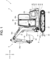
- the boom 31 is supported by a swing bracket 41 of the upper revolving body 4.
- the boom 31 is rotated by a boom cylinder 31a.
- the boom cylinder 31a has a base end part supported by the swing bracket 41 and is telescopically movable.
- the arm 32 is supported by the boom 31.
- the arm 32 is rotated by an arm cylinder 32a.
- the arm cylinder 32a has a base end part supported by the boom 31 and is telescopically movable.
- the bucket 33 is supported by the arm 32.
- a bucket 33 is rotated by a bucket cylinder 33a.
- the bucket cylinder 33a has a base end part supported by the arm 32 and is telescopically movable.
- the boom cylinder 31a, the arm cylinder 32a, and the bucket cylinder 33a are constituted by a hydraulic cylinder, respectively.
- the swing bracket 41 is disposed on a front side of the upper revolving body 4, and the counterweight 43 is disposed on a rear side.
- the counterweight 43 is a weight for maintaining a favorable weight balance in the front-back direction of the hydraulic excavator 1 particularly during an excavation work or the like. By means of the counterweight 43, the hydraulic excavator 1 can stably perform works.
- the swing bracket 41, the revolving bearing 42, the counterweight 43, and the revolving motor 44 are mounted on the revolving frame 50, which will be described in detail later. A configuration of the revolving frame 50 will also be described later.
- the engine EG is a drive source of the hydraulic excavator 1.
- the engine EG is constituted by a diesel engine, but this is not limiting, and it may be constituted by a gasoline engine, for example.
- the steering portion 46 is provided on an upper part of the upper revolving body 4.
- the driver's seat 46a is disposed on the steering portion 46.
- a plurality of steering members 46b are disposed around the driver's seat 46a.
- the plurality of steering members 46b are configured by including a lever, a switch, a pedal, and the like.
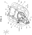
- the swing bracket 41 is supported by the swing support portion 51. More specifically, on a rear side of the swing bracket 41, a plurality of through holes (not shown) penetrating in the up-down direction are provided in the up-down direction.
- the swing bracket 41 is disposed such that each of the aforementioned through holes corresponds to the first coupling hole 51a and the second coupling hole 51b.
- An upper coupling pin P1 is inserted into the first coupling hole 51a and some of the through holes from above.
- a lower coupling pin P2 is inserted into the second coupling hole 51b and the remaining through holes from below.
- the upper coupling pin P1 and the lower coupling pin P2 are inserted such that axial directions thereof are along the up-down direction.
- the swing bracket 41 is rotatably supported with the upper coupling pin P1 and the lower coupling pin P2 as rotating shafts.
- a distal end part of the swing cylinder 41a is coupled with the right side of the swing bracket 41.
- a base end part of the swing cylinder 41a is supported by the cylinder support portion 52 of the revolving frame 50.
- the cylinder support portion 52 is provided on a rear of the swing support portion 51 and to the right of the revolving-bearing support portion 53, which will be described later, in the revolving frame 50.
- the swing cylinder 41a is constituted by a hydraulic cylinder and is telescopically movable.
- the swing bracket 41 swings in the left-right direction (width direction) with the upper coupling pin P1 and the lower coupling pin P2 as the rotating shafts.
- the swing bracket 41 supports the boom 31 as described above (see FIG. 1 ). Therefore, the swing support portion 51 provided on the revolving frame 50 swingably supports the boom 31 (work machine 3) in the left-right direction via the swing bracket 41.
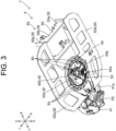
- the outer ring 42a is fixed to the revolving-bearing support portion 53 from below by a plurality of bolts B1.
- a part (annular part on a plan view) to which the outer ring 42a is fixed constitutes the revolving-bearing support portion 53.
- the revolving-bearing support portion 53 which supports the outer ring 42a (the revolving bearing 42) is provided.
- the inner ring 42b is fixed to an upper part of the lower traveling body 2.
- the revolving-motor support portion 54 is provided on a right front part of the annular revolving-bearing support portion 53 integrally by overlapping the revolving-bearing support portion 53 (see FIG. 4 ).
- the revolving motor 44 is supported by the revolving-motor support portion 54 with the rotary shaft 44a directed downward. That is, in the revolving frame 50, the revolving-motor support portion 54 which supports the revolving motor 44 is provided.
- the revolving-motor support portion 54 is provided so as to protrude from a fixed side to the outer ring 42a in the revolving-bearing support portion 53 toward an inner side of the inner ring 42b on a plan view.
- a gear 44b is provided on an outer peripheral surface of the rotary shaft 44a of the revolving motor 44.
- the gear 44b is inserted into an insertion hole 54a (see FIG. 4 ) of the revolving-motor support portion 54 from above and meshes with the inner ring 42b of the revolving bearing 42.
- the gear 44b rotates together with the rotary shaft 44a, the inner ring 42b rotates relative to the outer ring 42a.
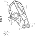
- FIG. 6 is a perspective view from front left illustrating the configuration of the first block.
- the first block 61 is made of casting and includes the swing support portion 51, the revolving-bearing support portion 53, the revolving-motor support portion 54, and a pair of vertical plates 61a (a first vertical plate 61a1 and a second vertical plate 61a2).
- the first vertical plate 61a1 and the second vertical plate 61a2 extend continuously from a rear part of the swing support portion 51 toward the rear side of the first block 61. More specifically, the first vertical plate 61a1 extends from a rear left end part of the swing support portion 51 toward the rear left side of the first block 61.
- the first vertical plate 61a1 is integrally provided such that a lower end part on the rear side intersects the left side of the rear end of the revolving-bearing support portion 53. Therefore, the first vertical plate 61a1 is integrally connected to the swing support portion 51 and the revolving-bearing support portion 53.
- a left edge of a front part of the second bottom plate 63a is joined to a right end part of the first block 61 (a part extending from a rear right end part of the swing support portion 51 to a front right part of the revolving bearing 42) (see FIG. 2 ).
- a front end part of the second reinforcing plate 63b is connected to a rear end part of the second vertical plate 61a2.
- the aforementioned beam member 56 and a connecting member 64 are provided on the rear of the first block 61.
- the beam member 56 is located between the second block 62 and the third block 63 in the left-right direction. More specifically, the beam member 56 is disposed such that a left end part thereof is in contact with a right side surface part of the first reinforcing plate 62b and a right end part thereof is in contact with a left side surface part of the second reinforcing plate 63b.
- each of the left and right end parts of the beam member 56 is joined to the first reinforcing plate 62b and the second reinforcing plate 63b by welding.
- the beam member 56 is connected to the first reinforcing plate 62b and the second reinforcing plate 63b. That is, the beam member 56 is connected to the second block 62 and the third block 63.
- FIG. 9 is a perspective view from front left illustrating a configuration of the other revolving frame 50.
- FIG. 10 is a perspective view from front left illustrating a configuration of the second block 62 and the third block 63 included in the other revolving frame 50.
- the other revolving frame 50 is configured by including the beam member 56, the first block 61, the second block 62, and the third block 63 similarly to the one revolving frame 50 (see FIG. 4 ). Note that, in the other revolving frame 50, the connecting member 64 (see FIG. 4 ) included in the one revolving frame 50 is removed.
- the beam member 56 and the first block 61 have the same configurations as those of the beam member 56 and the first block 61 shown in FIG. 4 and the like. That is, the other revolving frame 50 has the same beam member 56 and the first block 61 as those of the one revolving frame 50.
- the second block 62 and the third block 63 are configured such that the second block 62 and the third block 63 shown in FIG. 4 and the like are shorter in the front-back direction. More specifically, the disposed positions of the front end parts of the second block 62 and the third block 63 with respect to the first block 61 are the same as the front end parts of the second block 62 and the third block 63 shown in FIG. 4 and the like. On the other hand, the rear end parts of the second block 62 and the third block 63 are located closer to the front (closer to the first block 61) than the rear end parts of the second block 62 and the third block 63 shown in FIG. 4 and the like.
- the other revolving frame 50 has the second block 62 and the third block 63 which are shorter in the front-back direction than the one revolving frame 50.
- the other revolving frame 50 is configured to be shorter than the one revolving frame 50 in the front-back direction while having the same first block 61 as that of the one revolving frame 50.
- the revolving frame 50 (machine body) for each of the hydraulic excavators 1 while using the same first block 61.
- the size (particularly, the length in the front-back direction) of the revolving frame 50 (machine body) for each of the hydraulic excavators 1 while using the same first block 61.
- the first block 61 can be shared by the revolving frames 50 having different sizes, it is not necessary to prepare the swing support portion 51 and the revolving-bearing support portion 53 for each of the revolving frames 50 having different sizes and to join (for example, to weld) the swing support portion 51 and the revolving-bearing support portion 53. Therefore, it is possible to avoid an increase in the number of types of the swing support portion 51 and the revolving-bearing support portion 53 correspondingly to the revolving frames 50 having different sizes. As a result, the manufacturing cost of the revolving frame 50 can be reduced.
- the first block 61 is a casting, a process of welding the swing support portion 51 and the revolving-bearing support portion 53 is not required, and the manufacture of the first block 61 is facilitated.
- the first block 61 has a pair of vertical plates 61a (the first vertical plate 61a1 and the second vertical plate 61a2 in this embodiment) connected to the swing support portion 51 and the revolving-bearing support portion 53.
- the second block 62 and the third block 63 have a reinforcing plate (the first reinforcing plate 62b and the second reinforcing plate 63b in this embodiment), respectively, connected to either one of the pair of vertical plates 61a (the first vertical plate 61a1 and the second vertical plate 61a2).
- the reinforcing plates (the first reinforcing plate 62b and the second reinforcing plate 63b) extend from one side to the other side in the one direction.
- the beam member 56 When the beam member 56 is connected particularly to each of the reinforcing plates (the first reinforcing plate 62b and the second reinforcing plate 63b) of the second block 62 and the third block 63, the swing support portion 51, the pair of vertical plates 61a, each of the aforementioned reinforcing plates, and the beam member 56 constitute a support structure having a frame shape on a plan view, and the revolving frame 50 is reinforced. From the viewpoint of further improving the strength of the revolving frame 50 with a small number of components, it is desirable that the beam member 56 is connected to each of the reinforcing plates (first reinforcing plate 62b and second reinforcing plate 63b) as shown in FIG. 4 .
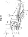
- FIG. 11 is a perspective view from lower left illustrating a configuration of the swing support portion 51.
- FIG. 12 is a perspective view from front left illustrating a vicinity of a front end part of the revolving frame 50 (that is, the swing support portion 51 in FIG. 1 in an enlarged manner.
- FIG. 13 is a perspective view from front left by omitting illustration of a first hydraulic pipe 73a included in a hydraulic pipe 73, which will be described later, in FIG. 12 .
- the lower traveling body 2, the boom cylinder 31a and the like are not shown for convenience.
- the swing support portion 51 includes an upper wall portion 51c, a lower wall portion 51d, and a rear wall portion 51e.
- the rear wall portion 51e is constituted by extending in the up-down direction.
- the rear wall portion 51e is provided with an opening portion 51e1 penetrating in the front-back direction.
- the upper wall portion 51c extends forward continuously from an upper end part of the rear wall portion 51e horizontally.
- the aforementioned first coupling hole 51a is provided in the front side of the upper wall portion 51c.
- the lower wall portion 51d extends forward continuously from a lower end part of the rear wall portion 51e horizontally.
- the aforementioned second coupling hole 51b is provided in the front side of the lower wall portion 51d.
- the upper wall portion 51c and the lower wall portion 51d are provided so as to protrude forward from the rear wall portion 51e.
- a space located in front of the rear wall portion 51e and between the upper wall portion 51c and the lower wall portion 51d (overlapping both the upper wall portion 51c and the lower wall portion 51d on a plan view) is referred to as an inside 51IN of the swing support portion 51.
- the second hydraulic pipe 73b is connected to the rear side of the joint portion 72.
- the second hydraulic pipe 73b extends rearward from the joint portion 72 through the inside 51IN (in particular, a rear side of the inside 51IN) of the swing support portion 51 and the opening portion 51e1 provided in the rear wall portion 51e of the swing support portion 51.
- the other end part of the second hydraulic pipe 73b is connected to hydraulic equipment (not shown) disposed on the rear of the rear wall portion 51e inside the upper revolving body 4.
- the aforementioned hydraulic equipment includes the control valve and the like described above.
- the hydraulic pipe 73 is provided by extending toward the boom 31 (work machine 3) through the inside 51IN of the swing support portion 51.
- the first hydraulic pipe 73a and the second hydraulic pipe 73b are constituted by hydraulic hoses.
- the first hydraulic pipe 73a and the second hydraulic pipe 73b may be constituted by, for example, a metal pipe, but the first hydraulic pipe 73a is preferably formed of a bendable hydraulic hose because the first hydraulic pipe 73a passes through the inside of the swing bracket 41 and the vicinity of the base end part of the boom 31.
- the support member 71 In the configuration in which the swing support portion 51 has the fixing portion 51f in the inside 51IN, the support member 71 is fixed to the fixing portion 51f, and the support member 71 supports the joint portion 72 of the hydraulic pipe 73, even when the hydraulic pipe 73 extending toward the work machine 3 passes through the inside 51IN of the swing support portion 51, the hydraulic pipe 73 is stably supported via the joint portion 72. That is, from the viewpoint of realizing stable support for the hydraulic pipe 73, the aforementioned configuration in which the support member 71 supports the joint portion 72 in the inside 51IN of the swing support portion 51 is preferable.
- the disposed position of the swing cylinder 41a is not limited to the above.
- the swing cylinder 41a may be disposed on the left end side of the swing bracket 41.
- the connecting member 64 may be provided as necessary.
- the connecting member 64 is provided at the rear part of the revolving frame 50, rigidity of the rear part of the revolving frame 50 in the left-right direction is increased. Therefore, particularly in the revolving frame 50 which is longer in the front-back direction shown in FIG. 4 and the like, a configuration including the connecting member 64 is preferable.
- the hydraulic excavator 1 may be configured to drive the hydraulic pump HP by using an electric motor instead of the engine EG (for example, an electric excavator).
- the crawler-type hydraulic excavator 1 has been explained as an example of the work machine, but the work machine is not limited to the crawler-type hydraulic excavator 1 and may be a construction machine such as the hydraulic excavator 1 (wheel excavator) in which the lower traveling body 2 has wheels (tires).
- the revolving frame of the work machine in the Supplementary Note (2) is characterized in that, in the revolving frame of the work machine in the Supplementary Note (1),
- the revolving frame of a work machine in the Supplementary Note (3) includes, in the revolving frame of the work machine in the Supplementary Note (2),
- the revolving frame of a work machine in the Supplementary Note (8) is characterized in that, in the revolving frame of the work machine in any one of the Supplementary Notes (1) to (7),
- the work machine in the Supplementary Note (9) includes a traveling body and
- the present invention is applicable to work machines such as a construction machine, for example.
Landscapes
- Engineering & Computer Science (AREA)
- Mining & Mineral Resources (AREA)
- Civil Engineering (AREA)
- General Engineering & Computer Science (AREA)
- Structural Engineering (AREA)
- Body Structure For Vehicles (AREA)
Priority Applications (1)
| Application Number | Priority Date | Filing Date | Title |
|---|---|---|---|
| EP23201140.3A EP4534762A1 (de) | 2023-10-02 | 2023-10-02 | Drehrahmen und arbeitsmaschine |
Applications Claiming Priority (1)
| Application Number | Priority Date | Filing Date | Title |
|---|---|---|---|
| EP23201140.3A EP4534762A1 (de) | 2023-10-02 | 2023-10-02 | Drehrahmen und arbeitsmaschine |
Publications (1)
| Publication Number | Publication Date |
|---|---|
| EP4534762A1 true EP4534762A1 (de) | 2025-04-09 |
Family
ID=88237453
Family Applications (1)
| Application Number | Title | Priority Date | Filing Date |
|---|---|---|---|
| EP23201140.3A Pending EP4534762A1 (de) | 2023-10-02 | 2023-10-02 | Drehrahmen und arbeitsmaschine |
Country Status (1)
| Country | Link |
|---|---|
| EP (1) | EP4534762A1 (de) |
Citations (4)
| Publication number | Priority date | Publication date | Assignee | Title |
|---|---|---|---|---|
| US6499556B1 (en) * | 1999-03-08 | 2002-12-31 | Komatsu, Ltd. | Revolving deck for earthmoving machinery |
| JP2005002572A (ja) * | 2003-06-09 | 2005-01-06 | Seirei Ind Co Ltd | 掘削作業車 |
| EP1580332A2 (de) * | 2004-03-22 | 2005-09-28 | Komatsu Ltd | Baumaschine |
| US20220228344A1 (en) | 2019-05-24 | 2022-07-21 | Caterpillar Sarl | Frame of construction machine |
-
2023
- 2023-10-02 EP EP23201140.3A patent/EP4534762A1/de active Pending
Patent Citations (4)
| Publication number | Priority date | Publication date | Assignee | Title |
|---|---|---|---|---|
| US6499556B1 (en) * | 1999-03-08 | 2002-12-31 | Komatsu, Ltd. | Revolving deck for earthmoving machinery |
| JP2005002572A (ja) * | 2003-06-09 | 2005-01-06 | Seirei Ind Co Ltd | 掘削作業車 |
| EP1580332A2 (de) * | 2004-03-22 | 2005-09-28 | Komatsu Ltd | Baumaschine |
| US20220228344A1 (en) | 2019-05-24 | 2022-07-21 | Caterpillar Sarl | Frame of construction machine |
Similar Documents
| Publication | Publication Date | Title |
|---|---|---|
| US6990757B2 (en) | Wheeled work vehicle | |
| US6772544B2 (en) | Wheeled work vehicle | |
| EP4534762A1 (de) | Drehrahmen und arbeitsmaschine | |
| JP6719116B2 (ja) | 作業機械 | |
| KR20080111053A (ko) | 굴착 작업기의 붐 | |
| JP5138654B2 (ja) | 建設機械の旋回フレーム | |
| JP6234330B2 (ja) | 作業機 | |
| JP2000230241A (ja) | 旋回作業車の作業機構造 | |
| JP4296182B2 (ja) | 掘削作業機のアーム | |
| JP3695301B2 (ja) | 後端小旋回型油圧ショベル | |
| JP2000273904A (ja) | 旋回作業機の配管構造 | |
| JP6510708B2 (ja) | 作業機 | |
| JP6898268B2 (ja) | 建設機械 | |
| EP4053344B1 (de) | Kopplungsvorrichtung für eine arbeitsmaschine | |
| JP7710096B2 (ja) | 建設機械 | |
| JP2015166513A (ja) | 建設機械の排土装置 | |
| JP4170881B2 (ja) | 旋回作業機 | |
| JP3273537B2 (ja) | 建設機械用バルブ支持装置 | |
| JP5001325B2 (ja) | 建設機械 | |
| JP3654539B2 (ja) | 作業機械 | |
| JP4357274B2 (ja) | 旋回作業機 | |
| JP2004036234A (ja) | 旋回式建設機械 | |
| JP2002348914A (ja) | 旋回作業機 | |
| JP4170880B2 (ja) | 旋回作業機 | |
| JP2004131947A (ja) | 油圧式作業車両 |
Legal Events
| Date | Code | Title | Description |
|---|---|---|---|
| PUAI | Public reference made under article 153(3) epc to a published international application that has entered the european phase |
Free format text: ORIGINAL CODE: 0009012 |
|
| STAA | Information on the status of an ep patent application or granted ep patent |
Free format text: STATUS: THE APPLICATION HAS BEEN PUBLISHED |
|
| AK | Designated contracting states |
Kind code of ref document: A1 Designated state(s): AL AT BE BG CH CY CZ DE DK EE ES FI FR GB GR HR HU IE IS IT LI LT LU LV MC ME MK MT NL NO PL PT RO RS SE SI SK SM TR |
|
| STAA | Information on the status of an ep patent application or granted ep patent |
Free format text: STATUS: REQUEST FOR EXAMINATION WAS MADE |
|
| 17P | Request for examination filed |
Effective date: 20251008 |