EP4538480A1 - Vorrichtung zur handhabung von elementen, die bei der herstellung von gerüsten oder stütztürmen eingeführt werden - Google Patents
Vorrichtung zur handhabung von elementen, die bei der herstellung von gerüsten oder stütztürmen eingeführt werden Download PDFInfo
- Publication number
- EP4538480A1 EP4538480A1 EP24169820.8A EP24169820A EP4538480A1 EP 4538480 A1 EP4538480 A1 EP 4538480A1 EP 24169820 A EP24169820 A EP 24169820A EP 4538480 A1 EP4538480 A1 EP 4538480A1
- Authority
- EP
- European Patent Office
- Prior art keywords
- scaffolding
- construction
- handling elements
- jib
- locking pin
- Prior art date
- Legal status (The legal status is an assumption and is not a legal conclusion. Google has not performed a legal analysis and makes no representation as to the accuracy of the status listed.)
- Pending
Links
Images





Classifications
-
- E—FIXED CONSTRUCTIONS
- E04—BUILDING
- E04G—SCAFFOLDING; FORMS; SHUTTERING; BUILDING IMPLEMENTS OR AIDS, OR THEIR USE; HANDLING BUILDING MATERIALS ON THE SITE; REPAIRING, BREAKING-UP OR OTHER WORK ON EXISTING BUILDINGS
- E04G5/00—Component parts or accessories for scaffolds
- E04G5/007—Devices and methods for erecting scaffolds, e.g. automatic scaffold erectors
-
- E—FIXED CONSTRUCTIONS
- E04—BUILDING
- E04G—SCAFFOLDING; FORMS; SHUTTERING; BUILDING IMPLEMENTS OR AIDS, OR THEIR USE; HANDLING BUILDING MATERIALS ON THE SITE; REPAIRING, BREAKING-UP OR OTHER WORK ON EXISTING BUILDINGS
- E04G7/00—Connections between parts of the scaffold
- E04G7/30—Scaffolding bars or members with non-detachably fixed coupling elements
- E04G7/301—Scaffolding bars or members with non-detachably fixed coupling elements for connecting bars or members which are parallel or in end-to-end relation
-
- E—FIXED CONSTRUCTIONS
- E04—BUILDING
- E04G—SCAFFOLDING; FORMS; SHUTTERING; BUILDING IMPLEMENTS OR AIDS, OR THEIR USE; HANDLING BUILDING MATERIALS ON THE SITE; REPAIRING, BREAKING-UP OR OTHER WORK ON EXISTING BUILDINGS
- E04G7/00—Connections between parts of the scaffold
- E04G7/30—Scaffolding bars or members with non-detachably fixed coupling elements
- E04G7/32—Scaffolding bars or members with non-detachably fixed coupling elements with coupling elements using wedges
-
- E—FIXED CONSTRUCTIONS
- E04—BUILDING
- E04G—SCAFFOLDING; FORMS; SHUTTERING; BUILDING IMPLEMENTS OR AIDS, OR THEIR USE; HANDLING BUILDING MATERIALS ON THE SITE; REPAIRING, BREAKING-UP OR OTHER WORK ON EXISTING BUILDINGS
- E04G7/00—Connections between parts of the scaffold
- E04G7/30—Scaffolding bars or members with non-detachably fixed coupling elements
- E04G7/34—Scaffolding bars or members with non-detachably fixed coupling elements with coupling elements using positive engagement, e.g. hooks or pins
-
- E—FIXED CONSTRUCTIONS
- E04—BUILDING
- E04G—SCAFFOLDING; FORMS; SHUTTERING; BUILDING IMPLEMENTS OR AIDS, OR THEIR USE; HANDLING BUILDING MATERIALS ON THE SITE; REPAIRING, BREAKING-UP OR OTHER WORK ON EXISTING BUILDINGS
- E04G5/00—Component parts or accessories for scaffolds
- E04G2005/008—Hoisting devices specially adapted as part of a scaffold system
Definitions
- the invention relates to the technical sector of scaffolding, but also to all structures performing the same function as scaffolding, such as in particular shoring towers or rolling scaffolding, which constitute variants thereof.
- It relates more specifically to a device for handling the elements used in the construction of such scaffolding, particularly at several levels, and is intended to optimize ergonomics during the assembly and disassembly of such scaffolding, but also the safety of operators.
- Scaffolding and other equivalent devices are traditionally made up of vertical uprights or poles, and horizontal components called ledgers. These ledgers are fixed to poles and extend between them, in order to provide the required stability to the scaffolding. These scaffolds receive, depending on their height, and on average every two meters, a horizontal platform which constitutes the floor, suitable for receiving the personnel called upon to work on the scaffolding. In addition, these scaffolds are equipped with guardrails, in order to prevent any risk of operators falling, said guardrails being generally fixed to the vertical uprights of the scaffolding.
- a lifting jib is conventionally used, capable of being reversibly fixed to said scaffolding, and generally to one of the posts forming part of its construction.
- Such jibs are traditionally made up of a vertical beam equipped with reversible fixing means on one of the scaffolding posts, a vertical beam from which a horizontal bar emanates, at the end of which a pulley can be mounted, thus ensuring the handling of the constituent elements of the scaffolding.
- These reversible fixing means are positioned at the upper and lower ends of the vertical beam respectively.
- the jib can therefore only be mounted on an existing structure, so that the working height of the operator(s), operating the pulley on the one hand, and ensuring the gripping of the element mounted using the jib on the other hand, is necessarily lower than his height, and generally lower than the height of his shoulders, since also, the vertical posts forming part of the construction of said scaffolding of the upper floors have not yet been put in place.
- the objective sought by the present invention is to overcome these drawbacks.
- the invention relates to a device for handling elements used in the construction of scaffolding or shoring towers or equivalent.
- This device comprises a lifting jib capable of being reversibly fixed to said scaffolding.
- the jib comprises at least one vertical beam provided with reversible fixing means on the scaffolding, on which is secured an extension or bar, in particular a horizontal one, at the end of which a lifting pulley or equivalent can be fixed.
- said reversible fixing means are positioned respectively at the level of the lower end of the vertical beam of the jib, and at a distance of between one third and two thirds of the height of said beam. Furthermore, said vertical beam is devoid of any other means of fixing to the scaffolding at the level of approximately one third of its upper part.
- the reversible fixing means with which the vertical beam of the jib is provided, consist of guide and locking pins, oriented substantially vertically, and intended to cooperate with complementary members arranged on the scaffolding.
- these complementary members consist of rosettes, fixed on the posts, and capable of ensuring the fixing of horizontal elements of the type of girders and guardrails.
- the lower centering pin is integral with the vertical beam
- the intermediate pin called the locking pin
- the locking pin is integral with a rod sliding within the vertical beam, the upper end of the rod being operable by the operator, and the beam being provided with a vertical through slot allowing the relative movement of said locking pin.
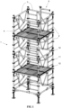
- FIG. 1 schematically illustrates a shoring tower (1) of conventional construction. This is made up of vertical posts or uprights (2), in this case distributed in a quadrilateral, said posts being associated vertically two by two, typically by interlocking and rotation of 1/8 of a turn, said posts being typically equipped with fire brigade connections.
- the posts are further equipped with rosettes (11, 12), intended to allow the fixing of horizontal elements on the posts, and in particular ledgers (3) or lateral structures integrating a guardrail.
- the braces (3) in addition to their stabilizing function, are also intended to receive floors (4), allowing operators to operate. On the shoring tower of the Figure 1 two levels of superimposed floors thus appear.
- a lifting jib (5) is installed at the level of one of the posts (2) of the highest level of the tower realized, as can be clearly seen on the figures 1 to 5 .
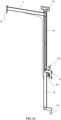
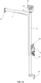
- the lifting jib (5) of the invention shown in more detail in relation to the figures 8 to 16 , consists of a vertical beam (6), from the upper end of which extends a horizontal crosspiece or bar (7), in this case perpendicular to the beam (6).
- the free end of the horizontal crosspiece (7) comprises a member (8), typically capable of receiving a pulley, in order to allow the effective lifting of the elements entering into the constitution of the shoring tower, or generally of a scaffold, these different elements being made up of the posts (2), the ledgers (3), the floors (4), in addition to the guardrails.
- the lifting jib (5) of the invention is provided with two means for removable attachment of the beam (6) to a post (2).
- the first removable fixing means is located at the lower end of the beam (6).
- it consists of a centering pin (10) integral with said lower end of the beam (6), and intended to be inserted into one of the orifices (20) of a rosette (11, 12), typically by fitting.
- the width and thickness of this centering pin (10) is compatible with the dimensions of the orifices (20), arranged radially within the rosette (11, 12).
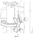
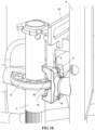
- the second removable fixing means consists on the one hand of a structure (15), described in more detail in relation to the figures 17 And 18 , and on the other hand, a locking pin (9) or intermediate pin, intended to be keyed there again at the level of a rosette (12).
- This locking pin (9) is positioned at a distance from the lower centering pin (10) of between one third and two thirds of the total height of the beam (6). It can be manually operated by the operator when he sets up the lifting jib (5).
- the lifting jib incorporates a vertical rod (14), capable of sliding within the beam (6) by a predetermined distance 1, typically of the order of ten centimeters.
- the locking pin (9) is secured to the rod (14), and not to the beam (6).
- the beam (6) is provided with a vertical through slot (16), which can be seen on the figure 8 , extending along a length corresponding substantially to the travel length 1 of the vertical rod (14) within the beam (6).
- the height of this through light or slot (16) is directly linked to the height of the locking pin (9), in order to allow sufficient travel to enable it to be unkeyed from a rosette (11, 12).
- This rod (14) can be actuated by a handle (13) according to a first embodiment of the invention ( figures 1 , 2 , 4 , 6 , 9 , 11 , 13 , 15 , 17 ).
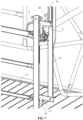
- the device comprises a second handle (22), integral with the unlocking pin (10), as illustrated in the figures 3 , 5 , 7 , 10 , 12 , 14 , 16 And 18
- This second embodiment thus comprising two handles (13, 22), makes it easier for the operator to work when assembling and disassembling the jib (5).
- the structure (15) mentioned above is described in more detail within the figures 17 And 18 . It is integral with the beam (6) and consists of a clamp or jaw whose two branches are capable of surrounding the rosette (11, 12), and more precisely of positioning themselves above and below said rosette, until they rest against the post (2). Said branches are pierced with a through light (17, 18), through which the locking pin (9) can be inserted.
- the through-holes (17, 18) are positioned directly above one of the through-holes (20) with which the rosette (11, 12) is provided, so that the locking pin can then pass through the upper through-hole (17), then one of the holes (20) of the rosette, and finally the lower through-hole (18), thus securing the positioning of the bracket (5) on the post (2) in question.
- the internal shape of the structure (15) defines a groove (19), the width of which corresponds, within the clearance, to the thickness of the rosette (11, 12).
- the locking pin in such a configuration, its shape is adapted in size and thickness. It adopts a generally triangular profile.
- This locking can be optimized by the operator by striking, for example using a hammer, the handle (13), or even the handle (22), or even on a striking zone (21), arranged in the vicinity of the handle (13), and extending substantially perpendicularly to the latter.
Landscapes
- Engineering & Computer Science (AREA)
- Architecture (AREA)
- Mechanical Engineering (AREA)
- Civil Engineering (AREA)
- Structural Engineering (AREA)
- Jib Cranes (AREA)
Applications Claiming Priority (1)
| Application Number | Priority Date | Filing Date | Title |
|---|---|---|---|
| FR2310938A FR3154133B1 (fr) | 2023-10-12 | 2023-10-12 | Dispositif de manutention d’elements entrant dans la realisation d’echafaudages ou de tours d’etaiement |
Publications (1)
| Publication Number | Publication Date |
|---|---|
| EP4538480A1 true EP4538480A1 (de) | 2025-04-16 |
Family
ID=89158142
Family Applications (1)
| Application Number | Title | Priority Date | Filing Date |
|---|---|---|---|
| EP24169820.8A Pending EP4538480A1 (de) | 2023-10-12 | 2024-04-12 | Vorrichtung zur handhabung von elementen, die bei der herstellung von gerüsten oder stütztürmen eingeführt werden |
Country Status (2)
| Country | Link |
|---|---|
| EP (1) | EP4538480A1 (de) |
| FR (1) | FR3154133B1 (de) |
Citations (7)
| Publication number | Priority date | Publication date | Assignee | Title |
|---|---|---|---|---|
| GB609428A (en) * | 1946-03-14 | 1948-09-30 | Ernest Goodall Malthouse | Improvements in or relating to scaffolds and gantries |
| GB906610A (en) * | 1959-12-31 | 1962-09-26 | Gen Electric Co Ltd | Improvements in or relating to portable lifting arrangements |
| US3143216A (en) * | 1961-01-16 | 1964-08-04 | Gus H Brunkan | Boom means |
| ES2337776T3 (es) * | 2002-02-20 | 2010-04-29 | Wilhelm Layher Verwaltungs-Gmbh | Dispositivo para montaje de un larguero de barandillo temporal de un andamiaje. |
| CA2830271A1 (en) * | 2012-10-19 | 2014-04-19 | Groupe Agf Acces Inc. | Rescue winch support for scaffolds and method of securing a rescue winch to a scaffold using same |
| WO2019102078A1 (fr) * | 2017-11-22 | 2019-05-31 | Commissariat A L'energie Atomique Et Aux Energies Alternatives | Dispositif de hissage portatif |
| DE202022101674U1 (de) * | 2022-03-30 | 2022-04-14 | China Railway No.3 Engineering Group Co., Ltd. | Vorrichtung mit einem Sicherheitsgurt-Aufhängepunkt für den Betrieb in großer Höhe |
-
2023
- 2023-10-12 FR FR2310938A patent/FR3154133B1/fr active Active
-
2024
- 2024-04-12 EP EP24169820.8A patent/EP4538480A1/de active Pending
Patent Citations (7)
| Publication number | Priority date | Publication date | Assignee | Title |
|---|---|---|---|---|
| GB609428A (en) * | 1946-03-14 | 1948-09-30 | Ernest Goodall Malthouse | Improvements in or relating to scaffolds and gantries |
| GB906610A (en) * | 1959-12-31 | 1962-09-26 | Gen Electric Co Ltd | Improvements in or relating to portable lifting arrangements |
| US3143216A (en) * | 1961-01-16 | 1964-08-04 | Gus H Brunkan | Boom means |
| ES2337776T3 (es) * | 2002-02-20 | 2010-04-29 | Wilhelm Layher Verwaltungs-Gmbh | Dispositivo para montaje de un larguero de barandillo temporal de un andamiaje. |
| CA2830271A1 (en) * | 2012-10-19 | 2014-04-19 | Groupe Agf Acces Inc. | Rescue winch support for scaffolds and method of securing a rescue winch to a scaffold using same |
| WO2019102078A1 (fr) * | 2017-11-22 | 2019-05-31 | Commissariat A L'energie Atomique Et Aux Energies Alternatives | Dispositif de hissage portatif |
| DE202022101674U1 (de) * | 2022-03-30 | 2022-04-14 | China Railway No.3 Engineering Group Co., Ltd. | Vorrichtung mit einem Sicherheitsgurt-Aufhängepunkt für den Betrieb in großer Höhe |
Also Published As
| Publication number | Publication date |
|---|---|
| FR3154133B1 (fr) | 2026-02-27 |
| FR3154133A1 (fr) | 2025-04-18 |
Similar Documents
| Publication | Publication Date | Title |
|---|---|---|
| EP1766157B1 (de) | Plattformstützvorrichtung zum anheben von lasten oder personen über die höhe einer struktur | |
| FR2531479A1 (fr) | Forage de puits avec unite de commande au sommet | |
| EP2450501A1 (de) | Vorrichtung zum Verschieben einer Verschalungsplattform für eine Bodenplatte und/oder einen Balkon | |
| FR2979931A1 (fr) | Potelet de garde-corps ou d'echafaudage equipe d'un bloqueur perfectionne | |
| EP2044273A1 (de) | Stützmast | |
| EP4367344A1 (de) | Gerüstturm und gerüst sowie verwendung des turms und des gerüsts | |
| EP0862675B1 (de) | Hubvorrichtung für dachstühle und eventuel für bauteile ruhend auf diesen dachstühlen | |
| FR3073834A1 (fr) | Dispositif de hissage portatif | |
| FR3154133A1 (fr) | Dispositif de manutention d’elements entrant dans la realisation d’echafaudages ou de tours d’etaiement | |
| EP2706166B1 (de) | Modularer Stützturm für Tief- und Hochbauarbeiten | |
| FR2946375A1 (fr) | Garde-corps comprenant deux rampes de glissement et echafaudage correspondant | |
| FR2989364A1 (fr) | Treuil de relevage d'un auvent de protection d'une structure pliable de travail en encorbellement et methode de relevage | |
| FR3027934A1 (fr) | Dispositif de liaison adapte pour relier de maniere amovible une plateforme de coffrage horizontale et un etai de soutenement | |
| EP2085537B1 (de) | Sicherheitsmontage- und -demontageverfahren eines fahrbaren Gerüsts, die dabei verwendeten Sicherheitsmontageprofile und das so erhaltene Gerüst | |
| EP2177691B1 (de) | Gerüststruktur mit integrierter Treppe | |
| FR2922929A1 (fr) | Lisse de garde-corps montable en securite sur un echafaudage protection comportant une telle lisse et procede de montage | |
| EP1700977B1 (de) | Verriegelungsvorrichtung für Rahmen von Gerüsten und Stütztürmen | |
| EP1878851A2 (de) | Verschalung mit einer Drehplattform mit automatischen Einrastverschluss in Betriebsposition | |
| EP0612899A1 (de) | Gerüstboden und Montageverfahren für Gerüste mit diesem Boden | |
| FR2683245A1 (fr) | Plateforme en encorbellement amovible, notamment pour circulation ou coffrage dans les ouvrages en beton. | |
| FR2956424A1 (fr) | Plateforme de travail en encorbellement | |
| EP1067253B1 (de) | Gerüstrahmen und Gerüst damit zusammengesetzt | |
| FR2981967A1 (fr) | Instrument de fixation a un element allonge pour un dispositif d'echafaudage | |
| FR3011262A1 (fr) | Echafaudage comprenant des garde-corps a montage en securite et faux barreau | |
| FR2995333A1 (fr) | Tour d'etaiement modulaire notamment pour le genie civil |
Legal Events
| Date | Code | Title | Description |
|---|---|---|---|
| PUAI | Public reference made under article 153(3) epc to a published international application that has entered the european phase |
Free format text: ORIGINAL CODE: 0009012 |
|
| STAA | Information on the status of an ep patent application or granted ep patent |
Free format text: STATUS: THE APPLICATION HAS BEEN PUBLISHED |
|
| AK | Designated contracting states |
Kind code of ref document: A1 Designated state(s): AL AT BE BG CH CY CZ DE DK EE ES FI FR GB GR HR HU IE IS IT LI LT LU LV MC ME MK MT NL NO PL PT RO RS SE SI SK SM TR |
|
| STAA | Information on the status of an ep patent application or granted ep patent |
Free format text: STATUS: REQUEST FOR EXAMINATION WAS MADE |
|
| 17P | Request for examination filed |
Effective date: 20250519 |
|
| STAA | Information on the status of an ep patent application or granted ep patent |
Free format text: STATUS: EXAMINATION IS IN PROGRESS |
|
| 17Q | First examination report despatched |
Effective date: 20250912 |
|
| GRAP | Despatch of communication of intention to grant a patent |
Free format text: ORIGINAL CODE: EPIDOSNIGR1 |
|
| STAA | Information on the status of an ep patent application or granted ep patent |
Free format text: STATUS: GRANT OF PATENT IS INTENDED |
|
| INTG | Intention to grant announced |
Effective date: 20260410 |