EP1700977B1 - Verriegelungsvorrichtung für Rahmen von Gerüsten und Stütztürmen - Google Patents
Verriegelungsvorrichtung für Rahmen von Gerüsten und Stütztürmen Download PDFInfo
- Publication number
- EP1700977B1 EP1700977B1 EP06358004.7A EP06358004A EP1700977B1 EP 1700977 B1 EP1700977 B1 EP 1700977B1 EP 06358004 A EP06358004 A EP 06358004A EP 1700977 B1 EP1700977 B1 EP 1700977B1
- Authority
- EP
- European Patent Office
- Prior art keywords
- frames
- balustrades
- balustrade
- locking
- orifices
- Prior art date
- Legal status (The legal status is an assumption and is not a legal conclusion. Google has not performed a legal analysis and makes no representation as to the accuracy of the status listed.)
- Expired - Lifetime
Links
Images


Classifications
-
- E—FIXED CONSTRUCTIONS
- E04—BUILDING
- E04G—SCAFFOLDING; FORMS; SHUTTERING; BUILDING IMPLEMENTS OR AIDS, OR THEIR USE; HANDLING BUILDING MATERIALS ON THE SITE; REPAIRING, BREAKING-UP OR OTHER WORK ON EXISTING BUILDINGS
- E04G7/00—Connections between parts of the scaffold
- E04G7/02—Connections between parts of the scaffold with separate coupling elements
- E04G7/06—Stiff scaffolding clamps for connecting scaffold members of common shape
- E04G7/20—Stiff scaffolding clamps for connecting scaffold members of common shape for ends of members only, e.g. for connecting members in end-to-end relation
-
- E—FIXED CONSTRUCTIONS
- E04—BUILDING
- E04G—SCAFFOLDING; FORMS; SHUTTERING; BUILDING IMPLEMENTS OR AIDS, OR THEIR USE; HANDLING BUILDING MATERIALS ON THE SITE; REPAIRING, BREAKING-UP OR OTHER WORK ON EXISTING BUILDINGS
- E04G5/00—Component parts or accessories for scaffolds
- E04G5/14—Railings
-
- E—FIXED CONSTRUCTIONS
- E04—BUILDING
- E04G—SCAFFOLDING; FORMS; SHUTTERING; BUILDING IMPLEMENTS OR AIDS, OR THEIR USE; HANDLING BUILDING MATERIALS ON THE SITE; REPAIRING, BREAKING-UP OR OTHER WORK ON EXISTING BUILDINGS
- E04G7/00—Connections between parts of the scaffold
- E04G7/30—Scaffolding bars or members with non-detachably fixed coupling elements
- E04G7/301—Scaffolding bars or members with non-detachably fixed coupling elements for connecting bars or members which are parallel or in end-to-end relation
Definitions
- the present invention relates to a locking device of the safety pin type for the construction of shoring towers and other scaffolds.
- the technical field of the invention is that of the design of shoring materials, scaffolding and security for building and special works.
- the locking device of the invention applies in particular to the construction of shoring towers type "tour ladder” whose vertical payload per amount can go up to 6 tons.
- Such towers are traditionally composed of support elements such as jacks or base plates providing a stable planar support on the ground and possibly interconnected in pairs by horizontal diagonals spacing the feet of the tower.
- first frames comprising amounts interconnected by cross members forming ladder bars, the amounts of each frame fitting on a support member and being locked thereon by a pin.
- Railings are then installed between the upper ends of the uprights of the frames, said railings comprising smooth connectors having at their ends means of connection to said uprights allowing on the one hand the interlocking of the railings on the first level of frames and secondly the establishment of a second level of frames above the first level, the railings are thus "pinched" between two successive frames, the link between these two levels of frames being secured with locking pins inserted into holes pierced right through the upper and lower ends of the frame uprights.
- the locking pins currently used for the construction of shoring and scaffolding towers have a straight pin for insertion into the holes in the posts of the tower or scaffold frames, and a tab formed or attached in the frame. extension of said pin and forming an angle relative thereto, said tab being shaped and oriented (or orientable) relative to the pin so as to allow locking of the pin in the holes of the amounts of the frames.
- Specific examples of such pins are described in the patent FR 1 082 293 and in the German utility model DE 9215110 U1 which discloses all the features of the preamble of claim 1.
- the present invention aims to provide a new type of locking for such shoring towers and scaffolding that overcomes the disadvantages of existing pins.
- a device for locking construction elements of shoring towers or scaffolds comprising at least two pins forming a "U" capable of being inserted through holes pierced transversely from one side to the assembly ends of said construction elements.
- Said building elements nest or juxtapose to form a said tower or scaffold so that said orifices at their ends are aligned to allow the passage of said pins of the device.
- the device according to the invention is as defined in claim 1.
- the device according to the invention comprises a non-return latch, said latch having a determined length allowing its tilting from a raised position of disengagement of the device to a tilted position of locking as and when the insertion of said pins in said orifices of said elements to be locked, said locking position being reached when said pins are fully inserted into said orifices of said elements, the length of said latch being such that the free end of said latch abuts against at least a fixed part of said 'a said railing after tipping.
- the device of the invention comprises a connection and sliding means integral with one end of said pins and for fixing said device on the rail of a said guardrail.
- the locking device of the invention is particularly advantageous in that it makes it possible to prevent slipping and falling of the pin of the device out of the locking holes of the frames, even when case of vibrations of the tower or blows on the device.
- the latch anti-return whose shape and length are adapted depending on the guardrail models, abuts the reservation of the railing installed between two successive frames nested one in the other, thus preventing the recoil of the pin and the locking device as a whole.
- To then remove the device simply raise the latch manually and remove the pin out of the holes to release the frames and the guard.
- said connecting means advantageously avoids the loss of the locking device, while allowing easy and quick placement thereof on the rail of a guardrail.
- said latch In its said locking position, said latch abuts against a protruding portion of the construction element on which the device is optionally fixed by means of its said connection and sliding means, which can be reversible connection means.
- the device according to the invention has the advantage of allowing the locking of two successive frames on a guard rail on either side of the end of the rail thereof.
- This is particularly advantageous when it is the guardrail which, at the ends of its smooth, comprises connector sleeves on which fit the upper and lower ends respectively of two successive frames of a ladder tower. It is thus possible to move the set of the tower by cranage without risk of dismemberment of the tower by separation of its elements.
- the locking device of the invention can advantageously be installed on the rail of a railing, said device sliding in a limited manner between the fastening means of said railing at the ends of said rail and the guard's bookings. body, as defined in claim 5.
- a guardrail comprising a locking device according to the invention integral and sliding at each end of its rail by means of said connecting and sliding means, in order to allow inserting at least two of said pins of said locking device into said holes of said two successive frame members to be locked with said shoring tower or scaffold, said latch of the locking device engaging with abutment against said reservation of said guard when it is tilted in its said locking position.
- said means for connecting and sliding the device is a reversible connection means which will thus remove if necessary the locking device of the railing rail.
- the locking device 1 With reference first to Figures 1A, 1B , the locking device 1 according to the invention, named in the following description "locking pin”, comprises two pins 11, 12 parallel and connected to one another by a cord conferring on the pin 1 a shape "U".
- the cord connecting said pins 11, 12 is welded to the outer surface of a tubular parallelepipedal section 14 constituting a connecting ring for threading the pin 1 on a complementary shape guide such as a railing rail as represented at Figures 2 to 4 .
- the ring 14 can be made by two halves of tube connected to each other by a hinge along one of their longitudinal edge, thus constituting a reversible connection and sliding means of the pin 1, said ring 14 can be kept closed after installation of the pin by any suitable means such as collars, bolts or other.
- the locking device of the invention is particularly suitable for securing assemblies of shoring tower and scaffolding elements such as frames and guardrails.
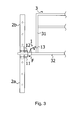
- the pin 1 of the invention may in particular be slidably mounted via its ring 14 on the rail 32 of a railing 3 between the end connectors 33 of said rail 32 and the reservation 31 of said guard body.
- Said connectors 33 comprise orifices 8 pierced right through in the axis of the pins 11, 12 of the pin when it is mounted on the rail 32 of the railing 3, said pins being thus insertable into said orifices 8 by sliding the pin 1 to the connectors 33.
- the latch 13 is in a raised position of release of the pin, are free end bearing against the reservation 31 guardrail 3 and the elastic return means 5 of the latch being in tension.
- Said uprights of the frames 2a, 2b also have at their upper and lower ends respectively orifices 7 pierced right through so that they correspond exactly in alignment with the orifices 8 pierced in the connectors 33 of the guardrail.
- the sliding of the pin causes a sliding and tilting of the latch 13 of the pin against the reservation 31 of the railing under the effect of the weight of the latch 13.
- This tilting of the latch 13 of the pin continues until it reaches its locking position when the pins 11, 12 are fully inserted into the openings 7, 8 of the frames 2a, 2b and the railing connectors 33 ( figure 4 ).
- the free end of said latch 13 engages against the connection of the reservation 31 of the railing 3 on the rail 32, thus preventing the retraction of the pin 1 and the withdrawal of the pins 11, 12 of the latter out of orifices 7, 8.
- the length of the latch 13 will be determined according to the distance between the reservation 31 of the guard rail 3 connectors 33 at the ends of the rail 32 and the length of the ring 14 on which is fixed the latch 13.
- the locking pin according to the invention allows an automatic locking of the pins 11, 12 in the openings of the frames 2a, 2b to lock, the particular folded shape of the latch 13 and the return means 5 thereof ensuring the maintaining said latch in the locked position, even in case of blows on the ends of the pins 11, 12 or vibrations.
- the pin 1 being fixed by its ring 14 on the rail 32 of the railing 3, it is completely captive, even in case of regular assembly and disassembly of said railing and / or transport thereof.
- the locking pin 1 of the invention being captive, it further allows when the latch 13 and in its locking position abuts against the reservation 31 of the railing to transport the shoring towers and scaffolds whose elements are locked. using cranes without risk of dismemberment of the elements constituting said tower or said scaffolding.
Landscapes
- Engineering & Computer Science (AREA)
- Architecture (AREA)
- Mechanical Engineering (AREA)
- Civil Engineering (AREA)
- Structural Engineering (AREA)
- Mutual Connection Of Rods And Tubes (AREA)
- Bridges Or Land Bridges (AREA)
- Movable Scaffolding (AREA)
Claims (7)
- Verriegelungsvorrichtung (1), die insbesondere für die Verriegelung von Rahmen (2a, 2b) und Geländern (3) von Stütztürmen oder Gerüsten ausgelegt ist, dadurch gekennzeichnet, dass sie wenigstens zwei ein "U" bildende Stifte (11, 12) umfasst, wobei eines der Enden der Stifte mit einem Verbindungs- und Schiebemittel (14) fest verbunden ist, das die Befestigung der Vorrichtung (1) an dem Holm (32) eines Geländers (3) ermöglicht, und dass sie eine kippbare Rücklaufsicherungsklinke (13) mit einer bestimmten Länge, bestehend aus einer vorzugsweise leicht gebogenen Platte umfasst, die an einer oberen Wand des Verbindungs- und Schiebemittels schwenkbar angebracht ist, wobei die Klinke geeignet ist, von einer hochgestellten Löseposition der Vorrichtung (1) bis zu einer gekippten Verriegelungsposition, in der ihr freies Ende an wenigstens einem festen Teil eines Geländers in Anschlag ist, entsprechend dem Einführen der Stifte (11, 12) in Öffnungen (7, 8) zu kippen, um Rahmen (2a, 2b) und Geländer (3), die diese Öffnungen (7, 8) jeweils aufweisen, untereinander zu verriegeln.
- Vorrichtung nach Anspruch 1, dadurch gekennzeichnet, dass das Verbindungs- und Schiebemittel (14) der Vorrichtung ein Mittel zum reversiblen Verbinden ist.
- Vorrichtung nach einem der Ansprüche 1 oder 2, dadurch gekennzeichnet, dass sie ein Mittel zum elastischen Rückstellen (5) der Klinke (13) umfasst.
- Vorrichtung nach einem der Ansprüche 1 bis 3, dadurch gekennzeichnet, dass die Schwenkachse der Klinke an dem Verbindungs- und Schiebemittel zu der Schiebeachse senkrecht verläuft und die Stifte zu der Schiebeachse parallel verlaufen.
- Geländer (3) für den Bau eines Stützturms oder eines Gerüstes, umfassend einen Holm (32), der mit den eine Aussparung bildenden Pfosten (31) des Geländers fest verbunden ist und der an seinen Enden mit Mitteln zum Befestigen (33) des Geländers an den Enden von Rahmen (2a, 2b) eines Stützturms oder eines Gerüstes ausgestattet ist, dadurch gekennzeichnet, dass es wenigstens eine Verriegelungsvorrichtung (1) wie in einem der Ansprüche 1 bis 4 definiert umfasst, die fest verbunden und geeignet ist, an dem Holm (32) über ein Verbindungs- und Schiebemittel (14) zwischen einem Ende dessen und einem eine Aussparung bildenden Pfosten (31) des Geländers verschoben zu werden, um das Einführen der Stifte (11, 12) der Verriegelungsvorrichtung in Öffnungen (7, 8) zu ermöglichen, die im Bereich der Verbindungsenden von zwei aufeinanderfolgenden Rahmenelementen (2a, 2b) und der Befestigungsmittel (33) des Geländers (3), die jeweils zu verriegeln sind, quer hindurch gebohrt sind, wobei die Klinke (13) der Verriegelungsvorrichtung eine derart bestimmte Länge hat, dass ihr freies Ende nach Kippen in die Verriegelungsposition in Anschlag an dem eine Aussparung bildenden Pfosten (31) des Geländers eingreift.
- Verfahren zum Errichten eines Stützturms oder eines Gerüstes durch Verbinden von Rahmen (2a, 2b) und Geländern (3), wobei die Geländer Holme (32) umfassen, die eine Aussparung bildende Pfosten (31) tragen und die an ihren Enden mit Befestigungsmitteln (33), welche von Öffnungen (8) quer durchbohrt sind, ausgestattet sind, und wobei die Rahmen ebenfalls an ihren oberen und unteren Enden Öffnungen (7), die quer in die Pfosten der Rahmen gebohrt sind, umfassen, Verfahren, wonach:- in einem ersten Schritt wenigstens zwei erste Rahmen (2a) und wenigstens ein Geländer (3) dadurch verbunden werden, dass die Befestigungsmittel (33) der Geländer zwischen den jeweiligen oberen Enden der ersten Rahmen (2a) derart eingefügt werden, dass die Öffnungen (7) der Rahmen exakt mit den Öffnungen (8) der Geländer korrespondieren, und- in einem zweiten Schritt zwei zweite Rahmen (2b) dadurch verbunden werden, dass ihre unteren Enden auf die Befestigungsmittel (33) der Geländer (3), welche die ersten Rahmen verbinden, derart aufgesteckt werden, dass die Öffnungen (7) der Rahmen exakt mit den Öffnungen (8) der Geländer korrespondieren, und- in einem dritten Schritt die Verbindung der ersten (2a) und zweiten Rahmen (2b) mit den Geländern (3) dadurch verriegelt wird, dass die Stifte (11, 12) von Verriegelungsvorrichtungen (1) nach einem der Ansprüche 1 bis 4 in die Öffnungen (7, 8) der Rahmen (2a, 2b) und der Geländer (3) eingesteckt werden und die Klinke (13) der Verriegelungsvorrichtungen (1) in Anschlag an die eine Aussparung bildenden Pfosten der Geländer (3) gekippt wird.
- Verfahren nach Anspruch 6, wobei die Geländer (3) mit dem Geländer, welches Gegenstand des Anspruchs 5 ist, übereinstimmen, und wobei die Verbindung der ersten und zweiten Rahmen (2a, 2b) mit den Geländern (3) durch Verschieben von Verriegelungsvorrichtungen (1), die durch ein Verbindungs- und Schiebemittel fest mit den Holmen (32) der Geländer verbunden sind, zwischen einem Befestigungsmittel des Holms und einem eine Aussparung bildenden Pfosten (31) des Geländers verriegelt wird, um das Einstecken der Stifte (11, 12) der Verriegelungsvorrichtung in Öffnungen (7, 8) der Rahmen (2a, 2b) und der Geländer (3) zu ermöglichen.
Applications Claiming Priority (1)
| Application Number | Priority Date | Filing Date | Title |
|---|---|---|---|
| FR0502318A FR2883015B1 (fr) | 2005-03-08 | 2005-03-08 | Dispositif de verrouillage pour cadres d'echafaudages et tours d'etaiement |
Publications (2)
| Publication Number | Publication Date |
|---|---|
| EP1700977A1 EP1700977A1 (de) | 2006-09-13 |
| EP1700977B1 true EP1700977B1 (de) | 2016-01-06 |
Family
ID=35044723
Family Applications (1)
| Application Number | Title | Priority Date | Filing Date |
|---|---|---|---|
| EP06358004.7A Expired - Lifetime EP1700977B1 (de) | 2005-03-08 | 2006-03-06 | Verriegelungsvorrichtung für Rahmen von Gerüsten und Stütztürmen |
Country Status (3)
| Country | Link |
|---|---|
| EP (1) | EP1700977B1 (de) |
| ES (1) | ES2566490T3 (de) |
| FR (1) | FR2883015B1 (de) |
Families Citing this family (2)
| Publication number | Priority date | Publication date | Assignee | Title |
|---|---|---|---|---|
| FR2959260B1 (fr) * | 2010-04-23 | 2012-05-18 | Trium Invest | Tour d'etaiement |
| FR2959261B1 (fr) * | 2010-04-23 | 2012-07-13 | Trium Invest | Element de garde-corps d'une tour d'etaiement unitaire, et tour d'etaiement le comportant. |
Family Cites Families (9)
| Publication number | Priority date | Publication date | Assignee | Title |
|---|---|---|---|---|
| FR1082293A (fr) * | 1953-08-17 | 1954-12-28 | étai métallique, tubulaire et télescopique | |
| FR2450324A1 (fr) * | 1979-02-27 | 1980-09-26 | Cinotto Simon | Dispositif de stabilisation pour panneaux verticaux |
| US5069309A (en) * | 1989-09-28 | 1991-12-03 | Emerson Electric Co. | Rolling tower scaffold and method and tooling apparatus for manufacturing the same |
| DE9215110U1 (de) * | 1992-11-06 | 1993-03-18 | Scozzari, Agostino, 7958 Laupheim | Bolzensicherung |
| DE9319180U1 (de) * | 1993-12-14 | 1994-02-10 | Hänlein, Helmut, 73257 Köngen | Riegelbolzen-Einheit mit geführtem Riegelbolzen, für längenverstellbare Betonschal- und Grubenstützen |
| JPH11247433A (ja) * | 1998-02-27 | 1999-09-14 | Fumio Fujiki | 足場用弧状コーナ接続部材 |
| FR2788804B1 (fr) * | 1999-01-27 | 2001-04-06 | Mills | Poteau de garde-corps |
| JP2001003563A (ja) * | 1999-06-25 | 2001-01-09 | Alinco Inc | 足場建枠用連結具 |
| US6443262B1 (en) * | 1999-12-30 | 2002-09-03 | Waco International Corporation | Tubular frame scaffolding |
-
2005
- 2005-03-08 FR FR0502318A patent/FR2883015B1/fr active Active
-
2006
- 2006-03-06 ES ES06358004.7T patent/ES2566490T3/es not_active Expired - Lifetime
- 2006-03-06 EP EP06358004.7A patent/EP1700977B1/de not_active Expired - Lifetime
Also Published As
| Publication number | Publication date |
|---|---|
| FR2883015A1 (fr) | 2006-09-15 |
| EP1700977A1 (de) | 2006-09-13 |
| ES2566490T3 (es) | 2016-04-13 |
| FR2883015B1 (fr) | 2008-11-07 |
Similar Documents
| Publication | Publication Date | Title |
|---|---|---|
| EP2097599B1 (de) | Mobiles verankerungs- und fallverhinderungsgerät | |
| FR2503754A1 (fr) | Pont suspendu | |
| EP2044273B1 (de) | Stützmast | |
| EP2450501A1 (de) | Vorrichtung zum Verschieben einer Verschalungsplattform für eine Bodenplatte und/oder einen Balkon | |
| EP4367344A1 (de) | Gerüstturm und gerüst sowie verwendung des turms und des gerüsts | |
| FR3050749A1 (fr) | Module pour realiser un escalier de chantier tournant, ensemble comportant au moins un tel module et escalier de chantier comportant au moins un tel ensemble | |
| FR2549458A1 (fr) | Dispositif de levage de poteaux | |
| EP0468907A1 (de) | Zusammenklappbare Stutz-Konsole für Wandschalungen | |
| FR2934000A1 (fr) | Dispositif de protection dite grimpante | |
| EP1700977B1 (de) | Verriegelungsvorrichtung für Rahmen von Gerüsten und Stütztürmen | |
| EP2706166B1 (de) | Modularer Stützturm für Tief- und Hochbauarbeiten | |
| EP0407680B1 (de) | Verfahren zum Verbinden einer vorgefertigten Gerüstbühne mit einer horizontalen Traverse, und vorgefertigte Gerüstbühne dazu | |
| FR3146317A1 (fr) | Tour d’échafaudage et échafaudage et utilisation de la tour et de l’échafaudage | |
| EP2085537B1 (de) | Sicherheitsmontage- und -demontageverfahren eines fahrbaren Gerüsts, die dabei verwendeten Sicherheitsmontageprofile und das so erhaltene Gerüst | |
| EP2586932B1 (de) | Verriegelungsvorrichtung einer Gerüststange mit einer Sprossenstange einer Gerüstvorrichtung | |
| FR2973056A1 (fr) | Echafaudage securise a garde corps | |
| EP2177691A1 (de) | Gerüststruktur mit integrierter Treppe | |
| FR2947849A1 (fr) | Jambe d'appui ou de stabilisation telescopique et dispositif comprenant une telle jambe | |
| FR2919009A1 (fr) | Echafaudage avec garde-corps de protection collective. | |
| FR2925089A1 (fr) | Procede de montage et demontage en securite d'un echafaudage roulant et lisses de montage de securite utilisees | |
| EP4538480A1 (de) | Vorrichtung zur handhabung von elementen, die bei der herstellung von gerüsten oder stütztürmen eingeführt werden | |
| FR2956684A1 (fr) | Dispositif de fixation d'une plateforme contre une paroi support | |
| FR2956424A1 (fr) | Plateforme de travail en encorbellement | |
| FR2942635A1 (fr) | Systeme garde-corps destine a eviter les chutes lors de travaux de toitures en terrasse. | |
| FR2683245A1 (fr) | Plateforme en encorbellement amovible, notamment pour circulation ou coffrage dans les ouvrages en beton. |
Legal Events
| Date | Code | Title | Description |
|---|---|---|---|
| PUAI | Public reference made under article 153(3) epc to a published international application that has entered the european phase |
Free format text: ORIGINAL CODE: 0009012 |
|
| AK | Designated contracting states |
Kind code of ref document: A1 Designated state(s): AT BE BG CH CY CZ DE DK EE ES FI FR GB GR HU IE IS IT LI LT LU LV MC NL PL PT RO SE SI SK TR |
|
| AX | Request for extension of the european patent |
Extension state: AL BA HR MK YU |
|
| RIN1 | Information on inventor provided before grant (corrected) |
Inventor name: ROLAND, REMY Inventor name: PENIN, MICHEL |
|
| 17P | Request for examination filed |
Effective date: 20070115 |
|
| 17Q | First examination report despatched |
Effective date: 20070216 |
|
| AKX | Designation fees paid |
Designated state(s): AT BE BG CH CY CZ DE DK EE ES FI FR GB GR HU IE IS IT LI LT LU LV MC NL PL PT RO SE SI SK TR |
|
| RAP1 | Party data changed (applicant data changed or rights of an application transferred) |
Owner name: JALMAT FINANCE |
|
| REG | Reference to a national code |
Ref country code: DE Ref legal event code: R079 Ref document number: 602006047649 Country of ref document: DE Free format text: PREVIOUS MAIN CLASS: E04G0007200000 Ipc: E04G0005140000 |
|
| GRAP | Despatch of communication of intention to grant a patent |
Free format text: ORIGINAL CODE: EPIDOSNIGR1 |
|
| INTG | Intention to grant announced |
Effective date: 20150528 |
|
| RIC1 | Information provided on ipc code assigned before grant |
Ipc: E04G 7/30 20060101ALI20150518BHEP Ipc: E04G 7/20 20060101ALI20150518BHEP Ipc: E04G 5/14 20060101AFI20150518BHEP |
|
| GRAS | Grant fee paid |
Free format text: ORIGINAL CODE: EPIDOSNIGR3 |
|
| GRAA | (expected) grant |
Free format text: ORIGINAL CODE: 0009210 |
|
| AK | Designated contracting states |
Kind code of ref document: B1 Designated state(s): AT BE BG CH CY CZ DE DK EE ES FI FR GB GR HU IE IS IT LI LT LU LV MC NL PL PT RO SE SI SK TR |
|
| REG | Reference to a national code |
Ref country code: GB Ref legal event code: FG4D Free format text: NOT ENGLISH |
|
| REG | Reference to a national code |
Ref country code: DE Ref legal event code: R081 Ref document number: 602006047649 Country of ref document: DE Owner name: ALTRAD COFFRAGE ET ETAIEMENT, FR Free format text: FORMER OWNER: JALMAT INDUSTRIE MEDITERRANEE, VELAUX, FR |
|
| REG | Reference to a national code |
Ref country code: CH Ref legal event code: EP |
|
| REG | Reference to a national code |
Ref country code: IE Ref legal event code: FG4D Free format text: LANGUAGE OF EP DOCUMENT: FRENCH |
|
| REG | Reference to a national code |
Ref country code: AT Ref legal event code: REF Ref document number: 769005 Country of ref document: AT Kind code of ref document: T Effective date: 20160215 |
|
| REG | Reference to a national code |
Ref country code: DE Ref legal event code: R096 Ref document number: 602006047649 Country of ref document: DE |
|
| REG | Reference to a national code |
Ref country code: CH Ref legal event code: NV Representative=s name: BOVARD AG, CH Ref country code: CH Ref legal event code: PFA Owner name: ALTRAD COFFRAGE ET ETAIEMENT, FR Free format text: FORMER OWNER: JALMAT FINANCE, FR Ref country code: CH Ref legal event code: PK Free format text: RECTIFICATION TITULAIRE |
|
| REG | Reference to a national code |
Ref country code: FR Ref legal event code: PLFP Year of fee payment: 11 |
|
| REG | Reference to a national code |
Ref country code: DE Ref legal event code: R081 Ref document number: 602006047649 Country of ref document: DE Owner name: ALTRAD COFFRAGE ET ETAIEMENT, FR Free format text: FORMER OWNER: JALMAT FINANCE, VELAUX, FR |
|
| REG | Reference to a national code |
Ref country code: ES Ref legal event code: FG2A Ref document number: 2566490 Country of ref document: ES Kind code of ref document: T3 Effective date: 20160413 Ref country code: PT Ref legal event code: SC4A Free format text: AVAILABILITY OF NATIONAL TRANSLATION Effective date: 20160405 |
|
| REG | Reference to a national code |
Ref country code: NL Ref legal event code: FP |
|
| REG | Reference to a national code |
Ref country code: LT Ref legal event code: MG4D |
|
| REG | Reference to a national code |
Ref country code: AT Ref legal event code: MK05 Ref document number: 769005 Country of ref document: AT Kind code of ref document: T Effective date: 20160106 |
|
| REG | Reference to a national code |
Ref country code: FR Ref legal event code: CD Owner name: ALTRAD COFFRAGE ET ETAIEMENT, FR Effective date: 20160517 |
|
| PG25 | Lapsed in a contracting state [announced via postgrant information from national office to epo] |
Ref country code: GR Free format text: LAPSE BECAUSE OF FAILURE TO SUBMIT A TRANSLATION OF THE DESCRIPTION OR TO PAY THE FEE WITHIN THE PRESCRIBED TIME-LIMIT Effective date: 20160407 Ref country code: FI Free format text: LAPSE BECAUSE OF FAILURE TO SUBMIT A TRANSLATION OF THE DESCRIPTION OR TO PAY THE FEE WITHIN THE PRESCRIBED TIME-LIMIT Effective date: 20160106 |
|
| PG25 | Lapsed in a contracting state [announced via postgrant information from national office to epo] |
Ref country code: SE Free format text: LAPSE BECAUSE OF FAILURE TO SUBMIT A TRANSLATION OF THE DESCRIPTION OR TO PAY THE FEE WITHIN THE PRESCRIBED TIME-LIMIT Effective date: 20160106 Ref country code: LV Free format text: LAPSE BECAUSE OF FAILURE TO SUBMIT A TRANSLATION OF THE DESCRIPTION OR TO PAY THE FEE WITHIN THE PRESCRIBED TIME-LIMIT Effective date: 20160106 Ref country code: LT Free format text: LAPSE BECAUSE OF FAILURE TO SUBMIT A TRANSLATION OF THE DESCRIPTION OR TO PAY THE FEE WITHIN THE PRESCRIBED TIME-LIMIT Effective date: 20160106 Ref country code: IS Free format text: LAPSE BECAUSE OF FAILURE TO SUBMIT A TRANSLATION OF THE DESCRIPTION OR TO PAY THE FEE WITHIN THE PRESCRIBED TIME-LIMIT Effective date: 20160506 Ref country code: PL Free format text: LAPSE BECAUSE OF FAILURE TO SUBMIT A TRANSLATION OF THE DESCRIPTION OR TO PAY THE FEE WITHIN THE PRESCRIBED TIME-LIMIT Effective date: 20160106 Ref country code: AT Free format text: LAPSE BECAUSE OF FAILURE TO SUBMIT A TRANSLATION OF THE DESCRIPTION OR TO PAY THE FEE WITHIN THE PRESCRIBED TIME-LIMIT Effective date: 20160106 |
|
| REG | Reference to a national code |
Ref country code: NL Ref legal event code: HC Owner name: ALTRAD COFFRAGE ET ETAIEMENT; FR Free format text: DETAILS ASSIGNMENT: VERANDERING VAN EIGENAAR(S), VERANDERING VAN NAAM VAN DE EIGENAAR(S); FORMER OWNER NAME: JALMAT FINANCE Effective date: 20160404 |
|
| REG | Reference to a national code |
Ref country code: DE Ref legal event code: R097 Ref document number: 602006047649 Country of ref document: DE |
|
| PG25 | Lapsed in a contracting state [announced via postgrant information from national office to epo] |
Ref country code: DK Free format text: LAPSE BECAUSE OF FAILURE TO SUBMIT A TRANSLATION OF THE DESCRIPTION OR TO PAY THE FEE WITHIN THE PRESCRIBED TIME-LIMIT Effective date: 20160106 Ref country code: EE Free format text: LAPSE BECAUSE OF FAILURE TO SUBMIT A TRANSLATION OF THE DESCRIPTION OR TO PAY THE FEE WITHIN THE PRESCRIBED TIME-LIMIT Effective date: 20160106 |
|
| PLBE | No opposition filed within time limit |
Free format text: ORIGINAL CODE: 0009261 |
|
| STAA | Information on the status of an ep patent application or granted ep patent |
Free format text: STATUS: NO OPPOSITION FILED WITHIN TIME LIMIT |
|
| PG25 | Lapsed in a contracting state [announced via postgrant information from national office to epo] |
Ref country code: CZ Free format text: LAPSE BECAUSE OF FAILURE TO SUBMIT A TRANSLATION OF THE DESCRIPTION OR TO PAY THE FEE WITHIN THE PRESCRIBED TIME-LIMIT Effective date: 20160106 Ref country code: RO Free format text: LAPSE BECAUSE OF FAILURE TO SUBMIT A TRANSLATION OF THE DESCRIPTION OR TO PAY THE FEE WITHIN THE PRESCRIBED TIME-LIMIT Effective date: 20160106 Ref country code: SK Free format text: LAPSE BECAUSE OF FAILURE TO SUBMIT A TRANSLATION OF THE DESCRIPTION OR TO PAY THE FEE WITHIN THE PRESCRIBED TIME-LIMIT Effective date: 20160106 |
|
| 26N | No opposition filed |
Effective date: 20161007 |
|
| REG | Reference to a national code |
Ref country code: FR Ref legal event code: PLFP Year of fee payment: 12 |
|
| PG25 | Lapsed in a contracting state [announced via postgrant information from national office to epo] |
Ref country code: BG Free format text: LAPSE BECAUSE OF FAILURE TO SUBMIT A TRANSLATION OF THE DESCRIPTION OR TO PAY THE FEE WITHIN THE PRESCRIBED TIME-LIMIT Effective date: 20160406 Ref country code: SI Free format text: LAPSE BECAUSE OF FAILURE TO SUBMIT A TRANSLATION OF THE DESCRIPTION OR TO PAY THE FEE WITHIN THE PRESCRIBED TIME-LIMIT Effective date: 20160106 |
|
| PGFP | Annual fee paid to national office [announced via postgrant information from national office to epo] |
Ref country code: MC Payment date: 20170220 Year of fee payment: 12 Ref country code: FR Payment date: 20170113 Year of fee payment: 12 Ref country code: DE Payment date: 20170316 Year of fee payment: 12 Ref country code: CH Payment date: 20170323 Year of fee payment: 12 |
|
| PGFP | Annual fee paid to national office [announced via postgrant information from national office to epo] |
Ref country code: NL Payment date: 20170215 Year of fee payment: 12 Ref country code: PT Payment date: 20170220 Year of fee payment: 12 Ref country code: GB Payment date: 20170323 Year of fee payment: 12 Ref country code: LU Payment date: 20170224 Year of fee payment: 12 Ref country code: BE Payment date: 20170327 Year of fee payment: 12 Ref country code: IE Payment date: 20170220 Year of fee payment: 12 |
|
| PGFP | Annual fee paid to national office [announced via postgrant information from national office to epo] |
Ref country code: IT Payment date: 20170317 Year of fee payment: 12 |
|
| PGFP | Annual fee paid to national office [announced via postgrant information from national office to epo] |
Ref country code: ES Payment date: 20170331 Year of fee payment: 12 |
|
| PG25 | Lapsed in a contracting state [announced via postgrant information from national office to epo] |
Ref country code: HU Free format text: LAPSE BECAUSE OF FAILURE TO SUBMIT A TRANSLATION OF THE DESCRIPTION OR TO PAY THE FEE WITHIN THE PRESCRIBED TIME-LIMIT; INVALID AB INITIO Effective date: 20060306 Ref country code: CY Free format text: LAPSE BECAUSE OF FAILURE TO SUBMIT A TRANSLATION OF THE DESCRIPTION OR TO PAY THE FEE WITHIN THE PRESCRIBED TIME-LIMIT Effective date: 20160106 |
|
| PG25 | Lapsed in a contracting state [announced via postgrant information from national office to epo] |
Ref country code: TR Free format text: LAPSE BECAUSE OF FAILURE TO SUBMIT A TRANSLATION OF THE DESCRIPTION OR TO PAY THE FEE WITHIN THE PRESCRIBED TIME-LIMIT Effective date: 20160106 |
|
| REG | Reference to a national code |
Ref country code: DE Ref legal event code: R119 Ref document number: 602006047649 Country of ref document: DE |
|
| PG25 | Lapsed in a contracting state [announced via postgrant information from national office to epo] |
Ref country code: PT Free format text: LAPSE BECAUSE OF NON-PAYMENT OF DUE FEES Effective date: 20180906 |
|
| REG | Reference to a national code |
Ref country code: CH Ref legal event code: PL |
|
| REG | Reference to a national code |
Ref country code: NL Ref legal event code: MM Effective date: 20180401 |
|
| GBPC | Gb: european patent ceased through non-payment of renewal fee |
Effective date: 20180306 |
|
| PG25 | Lapsed in a contracting state [announced via postgrant information from national office to epo] |
Ref country code: MC Free format text: LAPSE BECAUSE OF NON-PAYMENT OF DUE FEES Effective date: 20180403 |
|
| REG | Reference to a national code |
Ref country code: BE Ref legal event code: HC Owner name: ALTRAD COFFRAGE ET ETAIEMENT; FR Free format text: DETAILS ASSIGNMENT: CHANGE OF OWNER(S), CHANGEMENT NOM PROPRIETAIRE; FORMER OWNER NAME: JALMAT FINANCE Effective date: 20160323 Ref country code: BE Ref legal event code: MM Effective date: 20180331 |
|
| REG | Reference to a national code |
Ref country code: IE Ref legal event code: MM4A |
|
| PG25 | Lapsed in a contracting state [announced via postgrant information from national office to epo] |
Ref country code: LU Free format text: LAPSE BECAUSE OF NON-PAYMENT OF DUE FEES Effective date: 20180306 Ref country code: NL Free format text: LAPSE BECAUSE OF NON-PAYMENT OF DUE FEES Effective date: 20180401 |
|
| PG25 | Lapsed in a contracting state [announced via postgrant information from national office to epo] |
Ref country code: DE Free format text: LAPSE BECAUSE OF NON-PAYMENT OF DUE FEES Effective date: 20181002 Ref country code: IE Free format text: LAPSE BECAUSE OF NON-PAYMENT OF DUE FEES Effective date: 20180306 |
|
| PG25 | Lapsed in a contracting state [announced via postgrant information from national office to epo] |
Ref country code: BE Free format text: LAPSE BECAUSE OF NON-PAYMENT OF DUE FEES Effective date: 20180331 Ref country code: GB Free format text: LAPSE BECAUSE OF NON-PAYMENT OF DUE FEES Effective date: 20180306 Ref country code: IT Free format text: LAPSE BECAUSE OF NON-PAYMENT OF DUE FEES Effective date: 20180306 Ref country code: CH Free format text: LAPSE BECAUSE OF NON-PAYMENT OF DUE FEES Effective date: 20180331 Ref country code: LI Free format text: LAPSE BECAUSE OF NON-PAYMENT OF DUE FEES Effective date: 20180331 |
|
| PG25 | Lapsed in a contracting state [announced via postgrant information from national office to epo] |
Ref country code: FR Free format text: LAPSE BECAUSE OF NON-PAYMENT OF DUE FEES Effective date: 20180331 |
|
| REG | Reference to a national code |
Ref country code: ES Ref legal event code: FD2A Effective date: 20190904 |
|
| PG25 | Lapsed in a contracting state [announced via postgrant information from national office to epo] |
Ref country code: ES Free format text: LAPSE BECAUSE OF NON-PAYMENT OF DUE FEES Effective date: 20180307 |