EP4538532A2 - Pompe à vide à spirales - Google Patents
Pompe à vide à spirales Download PDFInfo
- Publication number
- EP4538532A2 EP4538532A2 EP25160041.7A EP25160041A EP4538532A2 EP 4538532 A2 EP4538532 A2 EP 4538532A2 EP 25160041 A EP25160041 A EP 25160041A EP 4538532 A2 EP4538532 A2 EP 4538532A2
- Authority
- EP
- European Patent Office
- Prior art keywords
- wall
- circular
- spiral
- vacuum pump
- groove
- Prior art date
- Legal status (The legal status is an assumption and is not a legal conclusion. Google has not performed a legal analysis and makes no representation as to the accuracy of the status listed.)
- Pending
Links
Images

Classifications
-
- F—MECHANICAL ENGINEERING; LIGHTING; HEATING; WEAPONS; BLASTING
- F04—POSITIVE - DISPLACEMENT MACHINES FOR LIQUIDS; PUMPS FOR LIQUIDS OR ELASTIC FLUIDS
- F04C—ROTARY-PISTON, OR OSCILLATING-PISTON, POSITIVE-DISPLACEMENT MACHINES FOR LIQUIDS; ROTARY-PISTON, OR OSCILLATING-PISTON, POSITIVE-DISPLACEMENT PUMPS
- F04C18/00—Rotary-piston pumps specially adapted for elastic fluids
- F04C18/02—Rotary-piston pumps specially adapted for elastic fluids of arcuate-engagement type, i.e. with circular translatory movement of co-operating members, each member having the same number of teeth or tooth-equivalents
- F04C18/0207—Rotary-piston pumps specially adapted for elastic fluids of arcuate-engagement type, i.e. with circular translatory movement of co-operating members, each member having the same number of teeth or tooth-equivalents both members having co-operating elements in spiral form
- F04C18/0215—Rotary-piston pumps specially adapted for elastic fluids of arcuate-engagement type, i.e. with circular translatory movement of co-operating members, each member having the same number of teeth or tooth-equivalents both members having co-operating elements in spiral form where only one member is moving
-
- F—MECHANICAL ENGINEERING; LIGHTING; HEATING; WEAPONS; BLASTING
- F04—POSITIVE - DISPLACEMENT MACHINES FOR LIQUIDS; PUMPS FOR LIQUIDS OR ELASTIC FLUIDS
- F04C—ROTARY-PISTON, OR OSCILLATING-PISTON, POSITIVE-DISPLACEMENT MACHINES FOR LIQUIDS; ROTARY-PISTON, OR OSCILLATING-PISTON, POSITIVE-DISPLACEMENT PUMPS
- F04C18/00—Rotary-piston pumps specially adapted for elastic fluids
- F04C18/02—Rotary-piston pumps specially adapted for elastic fluids of arcuate-engagement type, i.e. with circular translatory movement of co-operating members, each member having the same number of teeth or tooth-equivalents
- F04C18/0207—Rotary-piston pumps specially adapted for elastic fluids of arcuate-engagement type, i.e. with circular translatory movement of co-operating members, each member having the same number of teeth or tooth-equivalents both members having co-operating elements in spiral form
- F04C18/0246—Details concerning the involute wraps or their base, e.g. geometry
- F04C18/0269—Details concerning the involute wraps
-
- F—MECHANICAL ENGINEERING; LIGHTING; HEATING; WEAPONS; BLASTING
- F04—POSITIVE - DISPLACEMENT MACHINES FOR LIQUIDS; PUMPS FOR LIQUIDS OR ELASTIC FLUIDS
- F04C—ROTARY-PISTON, OR OSCILLATING-PISTON, POSITIVE-DISPLACEMENT MACHINES FOR LIQUIDS; ROTARY-PISTON, OR OSCILLATING-PISTON, POSITIVE-DISPLACEMENT PUMPS
- F04C23/00—Combinations of two or more pumps, each being of rotary-piston or oscillating-piston type, specially adapted for elastic fluids; Pumping installations specially adapted for elastic fluids; Multi-stage pumps specially adapted for elastic fluids
- F04C23/008—Hermetic pumps
-
- F—MECHANICAL ENGINEERING; LIGHTING; HEATING; WEAPONS; BLASTING
- F04—POSITIVE - DISPLACEMENT MACHINES FOR LIQUIDS; PUMPS FOR LIQUIDS OR ELASTIC FLUIDS
- F04C—ROTARY-PISTON, OR OSCILLATING-PISTON, POSITIVE-DISPLACEMENT MACHINES FOR LIQUIDS; ROTARY-PISTON, OR OSCILLATING-PISTON, POSITIVE-DISPLACEMENT PUMPS
- F04C25/00—Adaptations of pumps for special use of pumps for elastic fluids
- F04C25/02—Adaptations of pumps for special use of pumps for elastic fluids for producing high vacuum
-
- F—MECHANICAL ENGINEERING; LIGHTING; HEATING; WEAPONS; BLASTING
- F04—POSITIVE - DISPLACEMENT MACHINES FOR LIQUIDS; PUMPS FOR LIQUIDS OR ELASTIC FLUIDS
- F04C—ROTARY-PISTON, OR OSCILLATING-PISTON, POSITIVE-DISPLACEMENT MACHINES FOR LIQUIDS; ROTARY-PISTON, OR OSCILLATING-PISTON, POSITIVE-DISPLACEMENT PUMPS
- F04C2230/00—Manufacture
- F04C2230/60—Assembly methods
- F04C2230/602—Gap; Clearance
-
- F—MECHANICAL ENGINEERING; LIGHTING; HEATING; WEAPONS; BLASTING
- F04—POSITIVE - DISPLACEMENT MACHINES FOR LIQUIDS; PUMPS FOR LIQUIDS OR ELASTIC FLUIDS
- F04C—ROTARY-PISTON, OR OSCILLATING-PISTON, POSITIVE-DISPLACEMENT MACHINES FOR LIQUIDS; ROTARY-PISTON, OR OSCILLATING-PISTON, POSITIVE-DISPLACEMENT PUMPS
- F04C2230/00—Manufacture
- F04C2230/90—Improving properties of machine parts
- F04C2230/91—Coating
-
- F—MECHANICAL ENGINEERING; LIGHTING; HEATING; WEAPONS; BLASTING
- F04—POSITIVE - DISPLACEMENT MACHINES FOR LIQUIDS; PUMPS FOR LIQUIDS OR ELASTIC FLUIDS
- F04C—ROTARY-PISTON, OR OSCILLATING-PISTON, POSITIVE-DISPLACEMENT MACHINES FOR LIQUIDS; ROTARY-PISTON, OR OSCILLATING-PISTON, POSITIVE-DISPLACEMENT PUMPS
- F04C2250/00—Geometry
-
- F—MECHANICAL ENGINEERING; LIGHTING; HEATING; WEAPONS; BLASTING
- F04—POSITIVE - DISPLACEMENT MACHINES FOR LIQUIDS; PUMPS FOR LIQUIDS OR ELASTIC FLUIDS
- F04C—ROTARY-PISTON, OR OSCILLATING-PISTON, POSITIVE-DISPLACEMENT MACHINES FOR LIQUIDS; ROTARY-PISTON, OR OSCILLATING-PISTON, POSITIVE-DISPLACEMENT PUMPS
- F04C2270/00—Control; Monitoring or safety arrangements
- F04C2270/70—Safety, emergency conditions or requirements
- F04C2270/701—Cold start
-
- F—MECHANICAL ENGINEERING; LIGHTING; HEATING; WEAPONS; BLASTING
- F04—POSITIVE - DISPLACEMENT MACHINES FOR LIQUIDS; PUMPS FOR LIQUIDS OR ELASTIC FLUIDS
- F04C—ROTARY-PISTON, OR OSCILLATING-PISTON, POSITIVE-DISPLACEMENT MACHINES FOR LIQUIDS; ROTARY-PISTON, OR OSCILLATING-PISTON, POSITIVE-DISPLACEMENT PUMPS
- F04C28/00—Control of, monitoring of, or safety arrangements for, pumps or pumping installations specially adapted for elastic fluids
- F04C28/06—Control of, monitoring of, or safety arrangements for, pumps or pumping installations specially adapted for elastic fluids specially adapted for stopping, starting, idling or no-load operation
Definitions
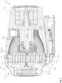
- the movable spiral component can be moved along a circular path via the eccentric section of the drive shaft, which is why this movable spiral component, together with its carrier, is also referred to as an orbiter.
- This movable spiral component thus performs a so-called centrally symmetric oscillation relative to the fixed spiral component, which is also referred to as "orbiting" or "wobbling.”
- the fixed spiral component, together with its carrier is accordingly also referred to as a stator.
- a crescent-shaped volume enclosed between a wall in the corresponding groove migrates increasingly inward within the groove as the movable spiral component orbits.
- the process gas to be pumped is conveyed from a radially outer gas inlet of the pumping system radially inward to a gas outlet of the pumping system, particularly one located in a center.
- the pumping system of the scroll vacuum pump according to the invention comprises a circular part and a spiral part, with the spiral part being arranged radially within the circular part.
- Both the circular part and the spiral part extend from an inlet end to an outlet end, with the terms "inlet” and “outlet” being chosen with reference to the pumping direction of the fluid to be pumped.
- the outlet end of the circular part is connected to the inlet end of the spiral part, so that an effective pumping distance extends from the inlet end of the circular part to to the outlet end of the spiral part.
- the outlet end of the spiral part is arranged radially centrally in the pump system, whereby the inlet end of the spiral part is automatically arranged radially further outward than the outlet end of the spiral part.
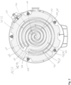
- the sickle-shaped volumes described above are formed by a wall element that engages in a groove.
- a circular circular wall is provided for the circular part, and a spiral spiral wall is provided for the spiral part, both of which extend from an orbiter carrier which, as part of the movable spiral component, interacts with the drive shaft, in particular with the eccentric section.
- the circular wall usually does not describe a full circle of 360°, but only a partial circle, for example, encompassing between 300° and 345°.
- the spiral wall in turn, can often be mathematically described as an involute.
- a circular groove and a spiral groove are provided in the stator carrier of the stationary spiral component.
- the circular wall engages the circular groove
- the spiral wall engages the spiral groove in such a way that crescent-shaped volumes form between these components.
- these volumes are displaced radially further inward, resulting in the fluid being pumped from the inlet end of the circular part to its outlet end, then to the inlet end of the spiral part, and through the spiral part to its outlet end, preferably radially centered in the pump system.
- the minimum gap that can be set between the circular wall and a corresponding wall of the circular groove in the circular part varies depending on whether the circular wall forms the radially outer or the radially inner boundary of the gap.
- the minimum distance is smaller if the circular wall is located radially outward and larger if the circular wall forms the radially inner boundary of the gap.
- the radial position of the circular wall will change until a constant operating temperature is reached, with the radial position shifting radially outwards in particular.
- This radial position change also occurs relative to the circular groove, since the arrangement of the circular groove on the movable spiral component means that it heats up more than the circular groove on the stationary spiral component.
- the difference in the minimum distances radially inward and radially outward between the circular wall and the corresponding wall of the circular groove provided according to the invention makes it possible for the minimum distances that occur during continuous operation to be equalized on both sides of the circular wall. This makes it possible to set the smallest possible minimum distance on both sides of the circular wall in order to achieve good sealing of the correspondingly formed crescent-shaped volumes at their tapered ends and thus minimize pumping losses.
- Circular parts are significantly less complex to manufacture, since the elements of a circular part, in particular the circular wall and/or the circular groove, can be manufactured as turned parts, in contrast to the spiral wall and/or Spiral grooves that require complex milling.
- the pumping effect of the scroll vacuum pump according to the invention can be improved without excessively increasing the manufacturing effort.
- the coating can be single-layer or multi-layer. In other words, the entire coating can also consist of several individual coatings. In multi-layer coatings, the individual layers can be made of the same coating material. Alternatively, at least two of the coating layers used can be made of different materials.
- FIG. 3 are for the Fig. 1 , 2
- the scroll vacuum pump 10 shown comprises the spiral part 100 (Figure A), the circular part 200 (Figure B) and the further circular part 300 (Figure C), each along its extension between the inlet ends 102, 202, 302 (on the right in the figures) and their outlet ends 104, 204, 304 (on the left in the figures).
- the selected illustration shows, for each position along this extension, the minimum possible distances 130, 132, 134, 136, 230, 232, 330, 323, which are achieved with a corresponding relative positioning of the orbiter carrier 42 to the stator carrier 32 (cf. Fig. 1 , 2 ) can be assumed.
Landscapes
- Engineering & Computer Science (AREA)
- Mechanical Engineering (AREA)
- General Engineering & Computer Science (AREA)
- Applications Or Details Of Rotary Compressors (AREA)
- Rotary Pumps (AREA)
Priority Applications (1)
| Application Number | Priority Date | Filing Date | Title |
|---|---|---|---|
| EP25160041.7A EP4538532A3 (fr) | 2025-02-25 | 2025-02-25 | Pompe à vide à spirales |
Applications Claiming Priority (1)
| Application Number | Priority Date | Filing Date | Title |
|---|---|---|---|
| EP25160041.7A EP4538532A3 (fr) | 2025-02-25 | 2025-02-25 | Pompe à vide à spirales |
Publications (2)
| Publication Number | Publication Date |
|---|---|
| EP4538532A2 true EP4538532A2 (fr) | 2025-04-16 |
| EP4538532A3 EP4538532A3 (fr) | 2025-08-27 |
Family
ID=94817609
Family Applications (1)
| Application Number | Title | Priority Date | Filing Date |
|---|---|---|---|
| EP25160041.7A Pending EP4538532A3 (fr) | 2025-02-25 | 2025-02-25 | Pompe à vide à spirales |
Country Status (1)
| Country | Link |
|---|---|
| EP (1) | EP4538532A3 (fr) |
Citations (3)
| Publication number | Priority date | Publication date | Assignee | Title |
|---|---|---|---|---|
| EP3153708A1 (fr) | 2015-10-06 | 2017-04-12 | Pfeiffer Vacuum Gmbh | Pompe a spirales et procede destine au fonctionnement d'une pompe a spirales |
| EP3617511A2 (fr) | 2019-10-07 | 2020-03-04 | Pfeiffer Vacuum Gmbh | Pompes à spirales et procédé de fabrication pour des telles pompes |
| EP3647599A2 (fr) | 2019-10-07 | 2020-05-06 | Pfeiffer Vacuum Gmbh | Pompe à vide, pompe d'extraction et procédé de fabrication des telles pompes |
Family Cites Families (4)
| Publication number | Priority date | Publication date | Assignee | Title |
|---|---|---|---|---|
| GB0304285D0 (en) * | 2003-02-25 | 2003-04-02 | Boc Group Plc | Scroll compressor |
| US7179067B2 (en) * | 2004-01-13 | 2007-02-20 | Scroll Technologies | Scroll compressor with wrap walls provided with an abradable coating and a load-bearing surface at radially outer locations |
| JP6226002B2 (ja) * | 2016-01-26 | 2017-11-08 | ダイキン工業株式会社 | スクロール圧縮機及びそれを備えた空気調和装置 |
| EP4506537B1 (fr) * | 2023-08-08 | 2025-10-08 | Pfeiffer Vacuum Technology AG | Pompe à vide à spirales |
-
2025
- 2025-02-25 EP EP25160041.7A patent/EP4538532A3/fr active Pending
Patent Citations (3)
| Publication number | Priority date | Publication date | Assignee | Title |
|---|---|---|---|---|
| EP3153708A1 (fr) | 2015-10-06 | 2017-04-12 | Pfeiffer Vacuum Gmbh | Pompe a spirales et procede destine au fonctionnement d'une pompe a spirales |
| EP3617511A2 (fr) | 2019-10-07 | 2020-03-04 | Pfeiffer Vacuum Gmbh | Pompes à spirales et procédé de fabrication pour des telles pompes |
| EP3647599A2 (fr) | 2019-10-07 | 2020-05-06 | Pfeiffer Vacuum Gmbh | Pompe à vide, pompe d'extraction et procédé de fabrication des telles pompes |
Also Published As
| Publication number | Publication date |
|---|---|
| EP4538532A3 (fr) | 2025-08-27 |
Similar Documents
| Publication | Publication Date | Title |
|---|---|---|
| DE4227332C2 (de) | Schraubenverdichter | |
| EP0295480B1 (fr) | Machine à déplacement positif | |
| DE69123898T2 (de) | Drehanlage für flüssige Medien | |
| DE2939945C2 (fr) | ||
| DE2529331C2 (de) | Schraubenkompressor | |
| DE3015628A1 (de) | Drucklager/kopplungseinrichtung und damit ausgeruestete schneckenmaschine | |
| DE2801206A1 (de) | Spiralartige einrichtung mit einem festen gekroepften kurbelantriebsmechanismus | |
| DE69202399T2 (de) | Strömungsmaschine in Spiralbauweise. | |
| DE7625941U1 (de) | Rotorverdraengermaschine mit einer schnecke | |
| DE1553238B2 (de) | Rotationskolbenmaschine | |
| DE3312280C2 (fr) | ||
| DE69205900T2 (de) | Verdrängermaschine nach dem Spiralprinzip. | |
| DE69108289T2 (de) | Gerotorpumpen. | |
| DE3911020A1 (de) | Schmierungsfreie rotationskolbenmaschine in schraubenbauweise | |
| WO2016016185A1 (fr) | Soupape d'un circuit de fluide d'un véhicule automobile | |
| WO2024132263A1 (fr) | Machine à déplacement positif | |
| EP4538532A2 (fr) | Pompe à vide à spirales | |
| EP0906512B1 (fr) | Pompe a ailettes | |
| DE69001910T2 (de) | Fluid-Kompressor. | |
| DE2636686A1 (de) | Dichtungsanordnung | |
| DE3139561C2 (fr) | ||
| EP3158198B1 (fr) | Machine à anneau liquide | |
| DE4134965A1 (de) | Spiralverdichter mit modifizierter kopfnut | |
| WO2007039405A1 (fr) | Pompe a palettes | |
| DE69835520T2 (de) | Schraubenverdichter mit verstellbarer volllastkapazität |
Legal Events
| Date | Code | Title | Description |
|---|---|---|---|
| PUAI | Public reference made under article 153(3) epc to a published international application that has entered the european phase |
Free format text: ORIGINAL CODE: 0009012 |
|
| STAA | Information on the status of an ep patent application or granted ep patent |
Free format text: STATUS: THE APPLICATION HAS BEEN PUBLISHED |
|
| AK | Designated contracting states |
Kind code of ref document: A2 Designated state(s): AL AT BE BG CH CY CZ DE DK EE ES FI FR GB GR HR HU IE IS IT LI LT LU LV MC ME MK MT NL NO PL PT RO RS SE SI SK SM TR |
|
| PUAL | Search report despatched |
Free format text: ORIGINAL CODE: 0009013 |
|
| AK | Designated contracting states |
Kind code of ref document: A3 Designated state(s): AL AT BE BG CH CY CZ DE DK EE ES FI FR GB GR HR HU IE IS IT LI LT LU LV MC ME MK MT NL NO PL PT RO RS SE SI SK SM TR |
|
| RIC1 | Information provided on ipc code assigned before grant |
Ipc: F04C 18/02 20060101AFI20250722BHEP Ipc: F04C 23/00 20060101ALI20250722BHEP Ipc: F04C 25/02 20060101ALI20250722BHEP Ipc: F04C 28/06 20060101ALI20250722BHEP |
|
| STAA | Information on the status of an ep patent application or granted ep patent |
Free format text: STATUS: REQUEST FOR EXAMINATION WAS MADE |
|
| 17P | Request for examination filed |
Effective date: 20260224 |
|
| STAA | Information on the status of an ep patent application or granted ep patent |
Free format text: STATUS: EXAMINATION IS IN PROGRESS |