EP4538563A1 - Dispositif de transmission de puissance à axe orthogonal - Google Patents
Dispositif de transmission de puissance à axe orthogonal Download PDFInfo
- Publication number
- EP4538563A1 EP4538563A1 EP23819964.0A EP23819964A EP4538563A1 EP 4538563 A1 EP4538563 A1 EP 4538563A1 EP 23819964 A EP23819964 A EP 23819964A EP 4538563 A1 EP4538563 A1 EP 4538563A1
- Authority
- EP
- European Patent Office
- Prior art keywords
- input shaft
- output shaft
- assembly
- link
- power transmission
- Prior art date
- Legal status (The legal status is an assumption and is not a legal conclusion. Google has not performed a legal analysis and makes no representation as to the accuracy of the status listed.)
- Withdrawn
Links
Images


Classifications
-
- F—MECHANICAL ENGINEERING; LIGHTING; HEATING; WEAPONS; BLASTING
- F16—ENGINEERING ELEMENTS AND UNITS; GENERAL MEASURES FOR PRODUCING AND MAINTAINING EFFECTIVE FUNCTIONING OF MACHINES OR INSTALLATIONS; THERMAL INSULATION IN GENERAL
- F16H—GEARING
- F16H21/00—Gearings comprising primarily only links or levers, with or without slides
- F16H21/46—Gearings comprising primarily only links or levers, with or without slides with movements in three dimensions [3D]
- F16H21/48—Gearings comprising primarily only links or levers, with or without slides with movements in three dimensions [3D] for conveying rotary motions
-
- F—MECHANICAL ENGINEERING; LIGHTING; HEATING; WEAPONS; BLASTING
- F16—ENGINEERING ELEMENTS AND UNITS; GENERAL MEASURES FOR PRODUCING AND MAINTAINING EFFECTIVE FUNCTIONING OF MACHINES OR INSTALLATIONS; THERMAL INSULATION IN GENERAL
- F16H—GEARING
- F16H21/00—Gearings comprising primarily only links or levers, with or without slides
- F16H21/10—Gearings comprising primarily only links or levers, with or without slides all movement being in, or parallel to, a single plane
- F16H21/12—Gearings comprising primarily only links or levers, with or without slides all movement being in, or parallel to, a single plane for conveying rotary motion
-
- F—MECHANICAL ENGINEERING; LIGHTING; HEATING; WEAPONS; BLASTING
- F16—ENGINEERING ELEMENTS AND UNITS; GENERAL MEASURES FOR PRODUCING AND MAINTAINING EFFECTIVE FUNCTIONING OF MACHINES OR INSTALLATIONS; THERMAL INSULATION IN GENERAL
- F16H—GEARING
- F16H57/00—General details of gearing
- F16H57/0006—Vibration-damping or noise reducing means specially adapted for gearings
-
- F—MECHANICAL ENGINEERING; LIGHTING; HEATING; WEAPONS; BLASTING
- F16—ENGINEERING ELEMENTS AND UNITS; GENERAL MEASURES FOR PRODUCING AND MAINTAINING EFFECTIVE FUNCTIONING OF MACHINES OR INSTALLATIONS; THERMAL INSULATION IN GENERAL
- F16H—GEARING
- F16H57/00—General details of gearing
- F16H57/0018—Shaft assemblies for gearings
- F16H57/0025—Shaft assemblies for gearings with gearing elements rigidly connected to a shaft, e.g. securing gears or pulleys by specially adapted splines, keys or methods
-
- F—MECHANICAL ENGINEERING; LIGHTING; HEATING; WEAPONS; BLASTING
- F16—ENGINEERING ELEMENTS AND UNITS; GENERAL MEASURES FOR PRODUCING AND MAINTAINING EFFECTIVE FUNCTIONING OF MACHINES OR INSTALLATIONS; THERMAL INSULATION IN GENERAL
- F16H—GEARING
- F16H57/00—General details of gearing
- F16H57/02—Gearboxes; Mounting gearing therein
- F16H57/021—Shaft support structures, e.g. partition walls, bearing eyes, casing walls or covers with bearings
-
- F—MECHANICAL ENGINEERING; LIGHTING; HEATING; WEAPONS; BLASTING
- F16—ENGINEERING ELEMENTS AND UNITS; GENERAL MEASURES FOR PRODUCING AND MAINTAINING EFFECTIVE FUNCTIONING OF MACHINES OR INSTALLATIONS; THERMAL INSULATION IN GENERAL
- F16H—GEARING
- F16H57/00—General details of gearing
- F16H57/02—Gearboxes; Mounting gearing therein
- F16H57/023—Mounting or installation of gears or shafts in the gearboxes, e.g. methods or means for assembly
-
- F—MECHANICAL ENGINEERING; LIGHTING; HEATING; WEAPONS; BLASTING
- F16—ENGINEERING ELEMENTS AND UNITS; GENERAL MEASURES FOR PRODUCING AND MAINTAINING EFFECTIVE FUNCTIONING OF MACHINES OR INSTALLATIONS; THERMAL INSULATION IN GENERAL
- F16H—GEARING
- F16H57/00—General details of gearing
- F16H57/02—Gearboxes; Mounting gearing therein
- F16H57/029—Gearboxes; Mounting gearing therein characterised by means for sealing the gearboxes, e.g. to improve airtightness
-
- F—MECHANICAL ENGINEERING; LIGHTING; HEATING; WEAPONS; BLASTING
- F16—ENGINEERING ELEMENTS AND UNITS; GENERAL MEASURES FOR PRODUCING AND MAINTAINING EFFECTIVE FUNCTIONING OF MACHINES OR INSTALLATIONS; THERMAL INSULATION IN GENERAL
- F16H—GEARING
- F16H57/00—General details of gearing
- F16H57/02—Gearboxes; Mounting gearing therein
- F16H57/031—Gearboxes; Mounting gearing therein characterised by covers or lids for gearboxes
-
- F—MECHANICAL ENGINEERING; LIGHTING; HEATING; WEAPONS; BLASTING
- F16—ENGINEERING ELEMENTS AND UNITS; GENERAL MEASURES FOR PRODUCING AND MAINTAINING EFFECTIVE FUNCTIONING OF MACHINES OR INSTALLATIONS; THERMAL INSULATION IN GENERAL
- F16H—GEARING
- F16H57/00—General details of gearing
- F16H57/02—Gearboxes; Mounting gearing therein
- F16H2057/02034—Gearboxes combined or connected with electric machines
-
- F—MECHANICAL ENGINEERING; LIGHTING; HEATING; WEAPONS; BLASTING
- F16—ENGINEERING ELEMENTS AND UNITS; GENERAL MEASURES FOR PRODUCING AND MAINTAINING EFFECTIVE FUNCTIONING OF MACHINES OR INSTALLATIONS; THERMAL INSULATION IN GENERAL
- F16H—GEARING
- F16H57/00—General details of gearing
- F16H57/02—Gearboxes; Mounting gearing therein
- F16H2057/02039—Gearboxes for particular applications
- F16H2057/02069—Gearboxes for particular applications for industrial applications
-
- F—MECHANICAL ENGINEERING; LIGHTING; HEATING; WEAPONS; BLASTING
- F16—ENGINEERING ELEMENTS AND UNITS; GENERAL MEASURES FOR PRODUCING AND MAINTAINING EFFECTIVE FUNCTIONING OF MACHINES OR INSTALLATIONS; THERMAL INSULATION IN GENERAL
- F16H—GEARING
- F16H57/00—General details of gearing
- F16H57/02—Gearboxes; Mounting gearing therein
- F16H2057/02091—Measures for reducing weight of gearbox
-
- F—MECHANICAL ENGINEERING; LIGHTING; HEATING; WEAPONS; BLASTING
- F16—ENGINEERING ELEMENTS AND UNITS; GENERAL MEASURES FOR PRODUCING AND MAINTAINING EFFECTIVE FUNCTIONING OF MACHINES OR INSTALLATIONS; THERMAL INSULATION IN GENERAL
- F16H—GEARING
- F16H57/00—General details of gearing
- F16H57/02—Gearboxes; Mounting gearing therein
- F16H57/028—Gearboxes; Mounting gearing therein characterised by means for reducing vibration or noise
Definitions
- the present inventive concept relates to an orthogonal-axis power transmission device, and more particularly, to an orthogonal-axis power transmission device which may change a power transmission direction to an orthogonal axis while reducing noise and vibration, also have a compact structure that significantly reduces manufacturing costs compared to the related art, and furthermore enable manufacturing in a size suitable for an intended use so as to be widely applied to various industrial machines.
- Power transmission devices may be largely classified into a rack and pinion that changes a rotational motion to a linear motion or a linear motion to a rotational motion, and a gear train that changes a rotation speed and torque while transferring only a rotational motion.
- the power transmission device are widely used for various industrial machines including semiconductor equipment, flat display equipment such as LCD, PDP, or OLED, and the like.
- the power transmission direction is generally linear, that is, along a straight axis.
- a linear shaft power transmission device adopts a method of using a reducer directly connected to a motor, so although the installation height is somewhat large, the device has the advantage of a very simple structure. Therefore, the linear shaft power transmission device is widely used.
- the bevel gear is a type of gear that operates as two gears are directly meshed with each other at a 45-degree angle with friction, so noise and vibration caused by the frictional motion are bound to be severe.
- noise and vibration caused by the frictional motion are bound to be severe.
- manufacturing costs inevitably increase because expensive, precisely manufactured bevel gears are used.
- the link assembly for changing a power transmission direction may change the power transmission direction input from the input shaft assembly, by 90 degrees, and transmit an output to the output shaft assembly in one-to-one correspondence
- the link assembly for changing a power transmission direction may include a main link member, an input shaft link member having one side connected to the input shaft assembly and the other side connected to one side of the main link member to be rotatable relative to each other, and an output shaft link member having one side connected to the output shaft assembly and the other side connected to the other side of the main link member to be rotatable relative to each other.
- the input shaft connection portion further may include a plurality of input shaft stop rings provided to fix a position of the input shaft sub-link or the input shaft power transmission pin.
- the output shaft connection portion may include an output shaft sub-link having one side connected to the output shaft link member and the other side connected to the main link member, a first output shaft bearing arranged in a connection area between the output shaft sub-link and the output shaft link member, an output shaft power transmission pin integrally connected to the output shaft link member, the output shaft sub-link, and the first output shaft bearing and transmitting power from a side of the output shaft link member to the output shaft sub-link, and a second output shaft bearing arranged in a connection area between the output shaft sub-link and the main link member.
- the input shaft connection portion and the output shaft connection portion have the same structure.
- the input shaft link member is key-coupled to the input shaft assembly by an input shaft key
- the output shaft link member is key-coupled to the output shaft assembly by an output shaft key
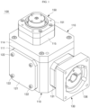
- the main structure assembly 110 may include a structure body 111 and a structure cover 114 which are disassembled and assembled from each other.
- the front cover 121 is fastened to a corresponding position by a front cover fastening member 122.
- the front cover fastening member 122 detachably fastens the front cover 121 to the structure body 111.
- the opening 125 in the front side of the structure body 111 may be shielded.
- a structure cover O-ring 117 is arranged between the structure cover 114 and the structure body 111.
- the structure cover O-ring 117 is arranged between the structure cover 114 and the structure body 111 and hermetically seals between the structure cover 114 and the structure body 111.
- the structure cover O-ring 117 may prevent leakage of internal lubricant between the structure cover 114 and the structure body 111.
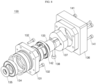
- the input shaft assembly 130 is a part which is connected to one side of the main structure assembly 110 and to which rotational power of a motor (not shown) is input.
- a clamp 137 for fastening a motor shaft of the motor to the input shaft adapter 133 is provided.
- the clamp 137 may be tightened by a clamp tightening bolt 138.
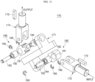
- the inertia moment balancer 171c is provided in the side regions of the disc type link body 171a and balances the moment of inertia during the rotational motion of the disc type link body 171a.
- the inertia moment balancer 171c is equally arranged in the side regions on both sides of the disc type link body 171a adjacent to the input shaft link member 172 and the output shaft link member 174.
- the inertia moment balancer 171c may also in the form of a hole.
- One end portion of the input shaft sub-link 181 is inserted into an open portion of the input shaft link member 172 as a Y-type link member, and the other end portion thereof is coupled to a hole or opening formed in an end portion of the main link member 171 as an S-type link member.
- the first input shaft bearing 182 and the second input shaft bearing 184 are installed in both end portions of the input shaft sub-link 181 to induce smooth rotations.
- the input shaft power transmission pin 183 is further used in the first input shaft bearing 182.
- the output shaft connection portion 190 is a means for connecting the main link member 171 and the output shaft link member 174 to be rotatable relative to each other.
- the output shaft connection portion 190 includes various parts and units.
- the output shaft connection portion 190 has substantially the same structure, function, and role as the input shaft connection portion 180, except a location thereof.
- the output shaft connection portion 190 may include an output shaft sub-link 191 having one side connected to the output shaft link member 174 and the other side connected to the main link member 171, a first output shaft bearing 192 arranged in a connection area between the output shaft sub-link 191 and the output shaft link member 174, an output shaft power transmission pin 193 integrally connected to the output shaft link member 174, the output shaft sub-link 191, and the first output shaft bearing 192 and transmitting power from the side of the output shaft link member 174 to the output shaft sub-link 191, and a second output shaft bearing 194 arranged in a connection area between the output shaft sub-link 191 and the main link member 171.
- a plurality of output shaft stop rings 195 are further used in the output shaft connection portion 190.
- the output shaft stop rings 195 is provided to fix the position of the output shaft sub-link 191 or the output shaft power transmission pin 193.
- the rotational power of the motor is input through the input shaft assembly 130, and then, while a power transmission direction is changed 90 degrees by the link assembly 170 for changing a power transmission direction, the rotational power may be transmitted through the output shaft assembly 150 in one-to-one correspondence.
- the power of the motor is output to the output shaft assembly 150 in one-to-one correspondence with only the direction thereof changed.
- an orthogonal-axis power transmission device may change a power transmission direction to the orthogonal axis while reducing noise and vibration, also have a compact structure that significantly reduces manufacturing costs compared to the related art, and furthermore enable manufacturing in a size suitable for an intended use so as to be widely applied to various industrial machines.
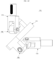
- FIG. 15 is a perspective view of a link assembly for changing a power transmission direction applied to an orthogonal-axis power transmission device according to another embodiment of the present inventive concept.
- a link assembly 270 for changing a power transmission direction applied to the present embodiment may also include a main link member 271, the input shaft link member 172 having one side connected to the input shaft assembly 130 and the other side connected to one side of the main link member 271 to be rotatable relative to each other, and the output shaft link member 174 having one side connected to the output shaft assembly 150 and the other side connected to the other side of the main link member 271 to be rotatable relative to each other.
- the main link member 271 applied to the present embodiment forms a place where the input shaft link member 172 and the output shaft link member 174 are connected to opposite end regions thereof.
- the main link member 271 is provided as an S-type link member in an S shape. Even when the main link member 271 is an S-type link member, the effects of the present inventive concept may be provided.
Landscapes
- Engineering & Computer Science (AREA)
- General Engineering & Computer Science (AREA)
- Mechanical Engineering (AREA)
- Transmission Devices (AREA)
Applications Claiming Priority (2)
| Application Number | Priority Date | Filing Date | Title |
|---|---|---|---|
| KR1020220069934A KR102655915B1 (ko) | 2022-06-09 | 2022-06-09 | 직각축 동력전달장치 |
| PCT/KR2023/004070 WO2023239026A1 (fr) | 2022-06-09 | 2023-03-28 | Dispositif de transmission de puissance à axe orthogonal |
Publications (1)
| Publication Number | Publication Date |
|---|---|
| EP4538563A1 true EP4538563A1 (fr) | 2025-04-16 |
Family
ID=89118577
Family Applications (1)
| Application Number | Title | Priority Date | Filing Date |
|---|---|---|---|
| EP23819964.0A Withdrawn EP4538563A1 (fr) | 2022-06-09 | 2023-03-28 | Dispositif de transmission de puissance à axe orthogonal |
Country Status (6)
| Country | Link |
|---|---|
| US (1) | US20250283527A1 (fr) |
| EP (1) | EP4538563A1 (fr) |
| JP (1) | JP2025515869A (fr) |
| KR (1) | KR102655915B1 (fr) |
| CN (1) | CN119384569A (fr) |
| WO (1) | WO2023239026A1 (fr) |
Family Cites Families (16)
| Publication number | Priority date | Publication date | Assignee | Title |
|---|---|---|---|---|
| US3075368A (en) * | 1960-10-13 | 1963-01-29 | Hulse Alexander | Drive mechanism |
| DE4116343A1 (de) * | 1991-05-18 | 1992-11-19 | Bosch Gmbh Robert | Handgefuehrtes elektrowerkzeug, insbesondere bohrmaschine |
| JP2588381Y2 (ja) * | 1992-01-29 | 1999-01-06 | オリエンタルモーター株式会社 | 電動機用直交軸減速機 |
| JP2681876B2 (ja) * | 1994-10-03 | 1997-11-26 | 株式会社中村自工 | ユニバーサルジョイントの製造方法 |
| JPH09144851A (ja) * | 1995-11-17 | 1997-06-03 | Aoki Seimitsu Kogyo Kk | 減速機ケーシング |
| JP2002349593A (ja) * | 2001-05-31 | 2002-12-04 | Ntn Corp | 等速自在継手 |
| JP3935033B2 (ja) * | 2002-09-06 | 2007-06-20 | 住友重機械工業株式会社 | 架台付の減速機のシリーズ |
| JP4603853B2 (ja) * | 2004-10-27 | 2010-12-22 | 株式会社Mstコーポレーション | 工具ホルダ |
| JP4722061B2 (ja) * | 2007-01-25 | 2011-07-13 | 株式会社ツバキエマソン | モータ付減速機におけるモータと減速機の連結に用いる連結用組立体のシリーズ |
| JP2014009764A (ja) * | 2012-06-29 | 2014-01-20 | Jtekt Corp | 回転軸装置の潤滑構造 |
| CN102990593A (zh) * | 2012-10-11 | 2013-03-27 | 宁波誉信工具制造有限公司 | 接头 |
| CN103644267B (zh) * | 2013-12-05 | 2016-08-17 | 燕山大学 | 万向拨齿钢球减速器 |
| KR102077378B1 (ko) * | 2015-04-17 | 2020-02-13 | 아틀라스 캅코 에어파워, 남로체 벤누트삽 | 스크루 압축기, 이에 적용되는 압축기 요소 및 기어 박스 |
| CN105782394B (zh) * | 2016-04-12 | 2018-02-09 | 燕山大学 | 直交轴钢球减速器 |
| JP6729855B2 (ja) * | 2016-11-14 | 2020-07-29 | Necエンベデッドプロダクツ株式会社 | 複数方向駆動装置、ロボット関節機構及び複数方向駆動方法 |
| US10801583B2 (en) * | 2018-07-01 | 2020-10-13 | Softwheel Ltd. | Device and method for transferring rotational power and method of using same |
-
2022
- 2022-06-09 KR KR1020220069934A patent/KR102655915B1/ko active Active
-
2023
- 2023-03-28 WO PCT/KR2023/004070 patent/WO2023239026A1/fr not_active Ceased
- 2023-03-28 US US18/860,606 patent/US20250283527A1/en active Pending
- 2023-03-28 CN CN202380045255.7A patent/CN119384569A/zh active Pending
- 2023-03-28 JP JP2024567516A patent/JP2025515869A/ja active Pending
- 2023-03-28 EP EP23819964.0A patent/EP4538563A1/fr not_active Withdrawn
Also Published As
| Publication number | Publication date |
|---|---|
| US20250283527A1 (en) | 2025-09-11 |
| WO2023239026A1 (fr) | 2023-12-14 |
| KR20230169595A (ko) | 2023-12-18 |
| CN119384569A (zh) | 2025-01-28 |
| KR102655915B1 (ko) | 2024-04-09 |
| JP2025515869A (ja) | 2025-05-20 |
Similar Documents
| Publication | Publication Date | Title |
|---|---|---|
| KR100301120B1 (ko) | 내접식 유성치차 감속기 | |
| EP2759743B1 (fr) | Réducteur de vitesse | |
| JP2582189B2 (ja) | モータ付直交歯車装置 | |
| US8535197B2 (en) | Speed changer assembly | |
| EP0944789B1 (fr) | Carter universel pour boites d'engrenage et groupes motoreducteurs a angle droit | |
| CA3064169C (fr) | Actionneur rotatif et actionneur lineaire | |
| EP4538563A1 (fr) | Dispositif de transmission de puissance à axe orthogonal | |
| JP2018514725A (ja) | 内接式遊星歯車減速機 | |
| JP2019150936A (ja) | ロボットの関節軸構造およびロボット | |
| JP2628983B2 (ja) | モータ付直交歯車装置 | |
| EP3489546B1 (fr) | Dispositif de réduction à engrenage planétaire pour réduction à très grande vitesse | |
| US7080570B2 (en) | Drive device for machine tools | |
| CA2081756A1 (fr) | Accouplement | |
| JP2023052825A (ja) | 歯車装置 | |
| JP4206703B2 (ja) | ギヤードモータ | |
| WO2023188088A1 (fr) | Structure d'articulation pour robot | |
| KR100352397B1 (ko) | 변속비 무한대 무단변속기 | |
| US10625302B2 (en) | Dynamic imbalanced force generator and an actuator comprising such a generator | |
| WO2021012200A1 (fr) | Robot et son procédé d'assemblage | |
| JP5897793B2 (ja) | 中間歯車減速機 | |
| JP2012087882A (ja) | ギヤードモータ | |
| RU14428U1 (ru) | Автомобиль с передними и задними ведущими колесами | |
| JP2019128024A (ja) | パワーユニットの密閉構造 | |
| JP2015223074A (ja) | ギヤードモータおよびギヤードモータの組立方法 | |
| JP2007292261A (ja) | 電動遮断機用減速機 |
Legal Events
| Date | Code | Title | Description |
|---|---|---|---|
| STAA | Information on the status of an ep patent application or granted ep patent |
Free format text: STATUS: THE INTERNATIONAL PUBLICATION HAS BEEN MADE |
|
| PUAI | Public reference made under article 153(3) epc to a published international application that has entered the european phase |
Free format text: ORIGINAL CODE: 0009012 |
|
| STAA | Information on the status of an ep patent application or granted ep patent |
Free format text: STATUS: REQUEST FOR EXAMINATION WAS MADE |
|
| 17P | Request for examination filed |
Effective date: 20241113 |
|
| AK | Designated contracting states |
Kind code of ref document: A1 Designated state(s): AL AT BE BG CH CY CZ DE DK EE ES FI FR GB GR HR HU IE IS IT LI LT LU LV MC ME MK MT NL NO PL PT RO RS SE SI SK SM TR |
|
| DAV | Request for validation of the european patent (deleted) | ||
| DAX | Request for extension of the european patent (deleted) | ||
| STAA | Information on the status of an ep patent application or granted ep patent |
Free format text: STATUS: THE APPLICATION IS DEEMED TO BE WITHDRAWN |
|
| 18D | Application deemed to be withdrawn |
Effective date: 20251001 |