EP4542064A2 - Procédé pour fixer des éléments de fixation sur du béton ou sur un mur - Google Patents
Procédé pour fixer des éléments de fixation sur du béton ou sur un mur Download PDFInfo
- Publication number
- EP4542064A2 EP4542064A2 EP25157145.1A EP25157145A EP4542064A2 EP 4542064 A2 EP4542064 A2 EP 4542064A2 EP 25157145 A EP25157145 A EP 25157145A EP 4542064 A2 EP4542064 A2 EP 4542064A2
- Authority
- EP
- European Patent Office
- Prior art keywords
- anchor
- load
- design
- fastening
- der
- Prior art date
- Legal status (The legal status is an assumption and is not a legal conclusion. Google has not performed a legal analysis and makes no representation as to the accuracy of the status listed.)
- Pending
Links
Images



Classifications
-
- E—FIXED CONSTRUCTIONS
- E04—BUILDING
- E04B—GENERAL BUILDING CONSTRUCTIONS; WALLS, e.g. PARTITIONS; ROOFS; FLOORS; CEILINGS; INSULATION OR OTHER PROTECTION OF BUILDINGS
- E04B1/00—Constructions in general; Structures which are not restricted either to walls, e.g. partitions, or floors or ceilings or roofs
- E04B1/38—Connections for building structures in general
- E04B1/41—Connecting devices specially adapted for embedding in concrete or masonry
-
- E—FIXED CONSTRUCTIONS
- E04—BUILDING
- E04C—STRUCTURAL ELEMENTS; BUILDING MATERIALS
- E04C5/00—Reinforcing elements, e.g. for concrete; Auxiliary elements therefor
- E04C5/08—Members specially adapted to be used in prestressed constructions
- E04C5/10—Ducts
-
- E—FIXED CONSTRUCTIONS
- E04—BUILDING
- E04G—SCAFFOLDING; FORMS; SHUTTERING; BUILDING IMPLEMENTS OR AIDS, OR THEIR USE; HANDLING BUILDING MATERIALS ON THE SITE; REPAIRING, BREAKING-UP OR OTHER WORK ON EXISTING BUILDINGS
- E04G21/00—Preparing, conveying, or working-up building materials or building elements in situ; Other devices or measures for constructional work
- E04G21/14—Conveying or assembling building elements
- E04G21/16—Tools or apparatus
- E04G21/18—Adjusting tools; Templates
- E04G21/1841—Means for positioning building parts or elements
- E04G21/185—Means for positioning building parts or elements for anchoring elements or elements to be incorporated in the structure
-
- E—FIXED CONSTRUCTIONS
- E04—BUILDING
- E04G—SCAFFOLDING; FORMS; SHUTTERING; BUILDING IMPLEMENTS OR AIDS, OR THEIR USE; HANDLING BUILDING MATERIALS ON THE SITE; REPAIRING, BREAKING-UP OR OTHER WORK ON EXISTING BUILDINGS
- E04G23/00—Working measures on existing buildings
- E04G23/02—Repairing, e.g. filling cracks; Restoring; Altering; Enlarging
- E04G23/0218—Increasing or restoring the load-bearing capacity of building construction elements
-
- E—FIXED CONSTRUCTIONS
- E21—EARTH OR ROCK DRILLING; MINING
- E21D—SHAFTS; TUNNELS; GALLERIES; LARGE UNDERGROUND CHAMBERS
- E21D21/00—Anchoring-bolts for roof, floor in galleries or longwall working, or shaft-lining protection
- E21D21/0026—Anchoring-bolts for roof, floor in galleries or longwall working, or shaft-lining protection characterised by constructional features of the bolts
- E21D21/0033—Anchoring-bolts for roof, floor in galleries or longwall working, or shaft-lining protection characterised by constructional features of the bolts having a jacket or outer tube
-
- F—MECHANICAL ENGINEERING; LIGHTING; HEATING; WEAPONS; BLASTING
- F16—ENGINEERING ELEMENTS AND UNITS; GENERAL MEASURES FOR PRODUCING AND MAINTAINING EFFECTIVE FUNCTIONING OF MACHINES OR INSTALLATIONS; THERMAL INSULATION IN GENERAL
- F16B—DEVICES FOR FASTENING OR SECURING CONSTRUCTIONAL ELEMENTS OR MACHINE PARTS TOGETHER, e.g. NAILS, BOLTS, CIRCLIPS, CLAMPS, CLIPS OR WEDGES; JOINTS OR JOINTING
- F16B25/00—Screws that cut thread in the body into which they are screwed, e.g. wood screws
- F16B25/001—Screws that cut thread in the body into which they are screwed, e.g. wood screws characterised by the material of the body into which the screw is screwed
- F16B25/0026—Screws that cut thread in the body into which they are screwed, e.g. wood screws characterised by the material of the body into which the screw is screwed the material being a hard non-organic material, e.g. stone, concrete or drywall
-
- G—PHYSICS
- G06—COMPUTING OR CALCULATING; COUNTING
- G06F—ELECTRIC DIGITAL DATA PROCESSING
- G06F30/00—Computer-aided design [CAD]
- G06F30/10—Geometric CAD
- G06F30/12—Geometric CAD characterised by design entry means specially adapted for CAD, e.g. graphical user interfaces [GUI] specially adapted for CAD
-
- E—FIXED CONSTRUCTIONS
- E04—BUILDING
- E04G—SCAFFOLDING; FORMS; SHUTTERING; BUILDING IMPLEMENTS OR AIDS, OR THEIR USE; HANDLING BUILDING MATERIALS ON THE SITE; REPAIRING, BREAKING-UP OR OTHER WORK ON EXISTING BUILDINGS
- E04G23/00—Working measures on existing buildings
- E04G23/02—Repairing, e.g. filling cracks; Restoring; Altering; Enlarging
- E04G23/0218—Increasing or restoring the load-bearing capacity of building construction elements
- E04G2023/0251—Increasing or restoring the load-bearing capacity of building construction elements by using fiber reinforced plastic elements
- E04G2023/0262—Devices specifically adapted for anchoring the fiber reinforced plastic elements, e.g. to avoid peeling off
-
- E—FIXED CONSTRUCTIONS
- E04—BUILDING
- E04H—BUILDINGS OR LIKE STRUCTURES FOR PARTICULAR PURPOSES; SWIMMING OR SPLASH BATHS OR POOLS; MASTS; FENCING; TENTS OR CANOPIES, IN GENERAL
- E04H9/00—Buildings, groups of buildings or shelters adapted to withstand or provide protection against abnormal external influences, e.g. war-like action, earthquake or extreme climate
- E04H9/02—Buildings, groups of buildings or shelters adapted to withstand or provide protection against abnormal external influences, e.g. war-like action, earthquake or extreme climate withstanding earthquake or sinking of ground
- E04H9/021—Bearing, supporting or connecting constructions specially adapted for such buildings
-
- F—MECHANICAL ENGINEERING; LIGHTING; HEATING; WEAPONS; BLASTING
- F16—ENGINEERING ELEMENTS AND UNITS; GENERAL MEASURES FOR PRODUCING AND MAINTAINING EFFECTIVE FUNCTIONING OF MACHINES OR INSTALLATIONS; THERMAL INSULATION IN GENERAL
- F16B—DEVICES FOR FASTENING OR SECURING CONSTRUCTIONAL ELEMENTS OR MACHINE PARTS TOGETHER, e.g. NAILS, BOLTS, CIRCLIPS, CLAMPS, CLIPS OR WEDGES; JOINTS OR JOINTING
- F16B37/00—Nuts or like thread-engaging members
- F16B37/12—Nuts or like thread-engaging members with thread-engaging surfaces formed by inserted coil-springs, discs, or the like; Independent pieces of wound wire used as nuts; Threaded inserts for holes
- F16B37/122—Threaded inserts, e.g. "rampa bolts"
- F16B37/125—Threaded inserts, e.g. "rampa bolts" the external surface of the insert being threaded
- F16B37/127—Threaded inserts, e.g. "rampa bolts" the external surface of the insert being threaded and self-tapping
-
- F—MECHANICAL ENGINEERING; LIGHTING; HEATING; WEAPONS; BLASTING
- F16—ENGINEERING ELEMENTS AND UNITS; GENERAL MEASURES FOR PRODUCING AND MAINTAINING EFFECTIVE FUNCTIONING OF MACHINES OR INSTALLATIONS; THERMAL INSULATION IN GENERAL
- F16B—DEVICES FOR FASTENING OR SECURING CONSTRUCTIONAL ELEMENTS OR MACHINE PARTS TOGETHER, e.g. NAILS, BOLTS, CIRCLIPS, CLAMPS, CLIPS OR WEDGES; JOINTS OR JOINTING
- F16B5/00—Joining sheets or plates, e.g. panels, to one another or to strips or bars parallel to them
- F16B5/06—Joining sheets or plates, e.g. panels, to one another or to strips or bars parallel to them by means of clamps or clips
- F16B5/0607—Joining sheets or plates, e.g. panels, to one another or to strips or bars parallel to them by means of clamps or clips joining sheets or plates to each other
- F16B5/0621—Joining sheets or plates, e.g. panels, to one another or to strips or bars parallel to them by means of clamps or clips joining sheets or plates to each other in parallel relationship
- F16B5/0642—Joining sheets or plates, e.g. panels, to one another or to strips or bars parallel to them by means of clamps or clips joining sheets or plates to each other in parallel relationship the plates being arranged one on top of the other and in full close contact with each other
-
- G—PHYSICS
- G06—COMPUTING OR CALCULATING; COUNTING
- G06F—ELECTRIC DIGITAL DATA PROCESSING
- G06F2119/00—Details relating to the type or aim of the analysis or the optimisation
- G06F2119/14—Force analysis or force optimisation, e.g. static or dynamic forces
Definitions
- the basis for the design of anchorages in concrete is the characteristic resistance of the anchor for the various failure mechanisms under tensile and shear loading.
- the most relevant failure mechanisms with regard to tensile loading are steel failure, concrete failure, and pull-out failure.
- the most important failure mechanisms under shear loading are also steel failure, concrete failure on the opposite side of the load, and concrete edge failure. If shear forces with a lever arm occur, a bending analysis must also be performed, which in turn influences the characteristic resistance of the anchor under steel failure and can significantly reduce it, depending on the length of the lifting arm.
- the expert can determine, based on specified design values for tensile load, shear load, and bending load, whether a planned fastening of fixtures to concrete or masonry using a group of anchors, referred to below as the "fastening group," is feasible, i.e., whether it meets the design requirements.
- the expert uses a computer program to interactively enter information representative of the tensile load, shear load, and, if applicable, bending load. This program automatically calculates whether the planned fastening with the planned anchors meets the design requirements.
- Conventional computer programs typically also indicate the extent to which the requirements are met.
- the expert can modify the design, for example, using fewer anchors or using less expensive anchors with a smaller cross-section, and re-examine the design.
- the computer program may indicate that a planned fastening does not meet the design requirements.
- the specialist may provide additional anchors and/or use anchors with a larger diameter and re-examine the modified design.
- the present invention is based on the object of providing an improved method for attaching attachments to masonry or concrete. This object is achieved by a method according to claim 1 and an associated computer program according to claim 16 and a design method according to claim 20. Advantageous further developments are specified in the dependent claims.
- the invention provides a method for fastening attachments with a group of anchors to a fastening base formed by concrete or masonry.
- the method is applicable to cases where the ratio V Sd /N Sd of the design value of the shear load V Sd and the design value of the tensile load N Sd of at least one anchor of the anchor group is: V Sd /N Sd ⁇ 0.3, preferably V Sd /N Sd ⁇ 0.6 and particularly preferably V Sd /N Sd ⁇ 1.0, and where for this anchor the characteristic resistances under shear load V Rk or under tensile load N Rk satisfy the following relationship: V Rk / N Rk ⁇ 1 , 1 .
- the characteristic resistances V Rk , N Rk each denote the lowest characteristic resistance resulting from the different failure modes to be taken into account in the design, for example V Rk,s , N Rk,s in the case of steel failure, particularly taking into account a possible lever arm, V Rk,c , N Rk,c in the case of concrete failure (concrete failure under tensile loading, concrete failure on the side facing away from the load or concrete edge failure under shear loading), etc.
- the angle of inclination ⁇ anchor is to be measured in the plane in which the shear load V Sd on which the design is based lies. Within this plane, the orientation of the angle ⁇ anchor is to be selected such that the angle between the longitudinal axis of the anchor and the resulting load is smaller than with vertical installation. This means that one head of the anchor is tilted in the direction of the shear load V Sd compared to the vertical installation position.
- the anchors used for this purpose are inserted at least partially at an angle ⁇ anchor to the surface of the fastening base which deviates from 90°.
- the parameter k can be selected in an interval from 0.8 to 1.34.
- the invention is based on the finding that for a certain class of applications an inclined anchor allows better load-bearing capacity than an anchor inserted perpendicular to the surface of the fastening base according to the prior art.
- Very good load-bearing capacities can be achieved if the angle ⁇ anchor is 75% of the angle at which the resultant tensile load and transverse load is to the surface normal of the surface of the fastening base, and this angle can be calculated using arctan (V Sd /N Sd ). This corresponds to the case where the parameter k takes on the value 1.
- the range 0.8 ⁇ k ⁇ 1.34 defines a corridor around this preferred choice of angle, which also promises good load-bearing capacity. Within this range, however, the value of the parameter k must always be selected so that ⁇ anchor ⁇ 75°. Preferably, the parameter k should be selected so that ⁇ anchor ⁇ 70°.
- steel failure limits the load level of the anchor.
- the characteristic resistance N Rk,s of the anchor at steel failure represents an upper limit that cannot be exceeded regardless of the nature of the base material, the arrangement in the base material, etc.
- the characteristic resistance under tensile loading N Rk relevant for the design is the lowest resistance that can result from the different failure mechanisms to be considered in the design.
- the inventor has systematically investigated various failure mechanisms of anchors in concrete for the case where, contrary to usual practice, the anchors are not installed perpendicular to the surface of the base material, but are inclined by an angle ⁇ anchor relative to the surface normal to the surface of the base material.
- significant improvements in the load-bearing capacity were found for applications in which V Rk /N Rk ⁇ 1.1, i.e. in which the characteristic resistance under shear stress V Rk is smaller or only insignificantly larger than the characteristic resistance N Rk under tensile stress.
- V Rk /N Rk The smaller the ratio V Rk /N Rk , the greater the improvements compared to conventional vertical installation. Improvements can be achieved in particular in comparison to vertical installation if the anchorage depth hef measured perpendicular to the surface is kept constant, which means that the anchor must be selected to be longer by a factor of 1/cos ( ⁇ anchor ) than with vertical installation. In practice, however, this does not pose any problems, since a slightly longer anchor hardly increases the costs. It is much more problematic, however, if anchors with a larger diameter have to be selected in order to comply with the design. These anchors are not only noticeably more expensive, but often cannot be used, especially in edge areas where design problems arise, because they lead to an increased risk of concrete edge failure (which ultimately leads to a lower value for V Rk ).
- the method only applies to cases where the design value for the shear load represents a significant proportion of the total load, and specifically to cases where V Sd /N Sd ⁇ 0.3.
- the increase in load-bearing capacity is either non-existent or not so significant that it does not justify the additional effort of an inclined installation.
- the parameter k can in principle be selected within the defined range, an additional condition should apply that k is always selected sufficiently small so that: ⁇ anchor ⁇ 75°, preferably ⁇ 70°, so as not to excessively complicate installation.
- a typical application is fastenings close to the edge, where the characteristic resistances of the transverse load are usually significantly smaller than the characteristic resistances for tensile load, i.e. V Rk ⁇ N Rk .
- V Rk,s 0.5* N Rk,s applies in good nutrition, so that in any case V Rk ⁇ N Rk .
- Bending loads can also significantly reduce the load-bearing capacity. As mentioned above, bending loads with a lever arm lead to a reduced value for V Rk , and thus also regularly lead to a situation where V Rk ⁇ N Rk .
- Bending stresses on the anchor must be taken into account if there is a non-compressive intermediate layer between the fixture and the base material, or if there is a gap or distance between the fixture and the base material. Bending stresses must also be taken into account if the fixture itself is not compressive, i.e., if it is not made of metal or concrete, but rather of wood, for example. Finally, bending stresses regularly play a role if the hole clearance of the connection is too large. As the distance between the load introduction into the anchor in the fixture and the joint between the fixture and the base material increases, the bending stress increases for the same effect on the fixture.
- the anchor is subjected to greater tensile loads than a vertically installed anchor under the same load situation.
- k ⁇ 1.2 preferably k ⁇ 1.15 and particularly preferably k ⁇ 1.1. This is at least the case when pressures can also be transmitted via the joint between the attachment and the fastening base.
- the anchor In installation positions with k ⁇ 1.2, the anchor is predominantly subjected to tensile stress (relative to the axis of the anchor, not to the surface normal of the fastening base), but also slightly subjected to shear force.
- the shear load is absorbed directly by the anchor being applied to the borehole wall in the attachment via pressures. Due to the redistribution of the reaction forces, the attachment is pressed onto the fastening base.
- the following therefore applies: k ⁇ 1.2, preferably k ⁇ 1.15 and particularly preferably k ⁇ 1.1.
- the at least one anchor is guided through a bore in the attachment, wherein the diameter of the bore exceeds the diameter of the anchor in a section in which it is accommodated in the bore in the assembled state by less than 22%, preferably less than 12%. With such a small amount of play of the anchor in the bore of the attachment, the transverse load can be effectively absorbed by compression.
- a non-compression-resistant material could be a non-compression-resistant plaster layer, wood, an insulation layer, or even simply air.
- the parameter k is preferably chosen to be larger, so that k ⁇ 1.1, preferably k ⁇ 1.2, and particularly preferably k ⁇ 1.25.
- this alternative standard installation angle ⁇ anchor should be between 35° and 55°, preferably between 40° and 50°, and particularly preferably approximately 45° to the perpendicular to the surface of the fastening base. be, because this can already achieve a significant improvement in a large number of applications.
- the alternative standard mounting bracket is at least taken into account if the ratio V Sd /N Sd of the design value of the shear load V Sd and the design value of the tensile load N Sd of at least one anchor in the anchor group is: V Sd /N Sd ⁇ 0.8 and preferably V Sd /N Sd ⁇ 1.0, and if for this anchor the characteristic resistances under shear load V Rk or under tensile load N Rk satisfy the following relationship: V Rk /N Rk ⁇ 1.1.
- a force that is also at a 45° angle to the surface normal i.e.
- the characteristic resistances under transverse stress V Rk or under tensile stress N Rk satisfy the following relationship: V Rk /N Rk ⁇ 1.0, preferably ⁇ 0.8, and particularly preferably ⁇ 0.6.
- the load transfer can also be distributed by arranging some of the anchors at an angle, while the others are arranged vertically.
- the tensile load can be assigned to the vertically arranged anchors and the transverse load to the inclined anchors. This allows for further optimization of the connection in anchor groups.
- the anchor mentioned which is installed at the angle ⁇ anchor defined above, can be an anchor closer to the edge within the anchor group, and the anchor group can contain an anchor further away from the edge, which is installed perpendicular to the surface of the fastening base.
- an anchor close to the edge must be suitable for supporting the full shear load, and the characteristic resistance to shear stress V Rk is lower in areas close to the edge than in areas far from the edge. Since the anchor inclined at the angle ⁇ anchor offers significantly greater resistance to shear loads, this criterion can be met more easily within the scope of the invention than in the prior art.
- an anchor is referred to as "near the edge” if it is less than ten times the effective, i.e. vertical, anchorage depth hef, preferably less than five times the effective manufacturing depth from the edge of the fastening base.
- the anchor mentioned which is inserted at the angle ⁇ anchor defined above, is an anchor further away from the edge within the anchor group, and the anchor group contains an anchor closer to the edge, which is accommodated in a slotted hole in the attachment part and is inserted perpendicular to the surface of the fastening base.
- a "slot" is understood to mean a hole that is sufficiently large that it can be assumed that an anchor received therein will not experience any significant shear load. This can be a slotted hole in the narrower sense of an elongated hole, but also a round hole with a sufficiently large diameter. In this embodiment, the anchor closest to the edge is thus inserted vertically and is therefore less suitable for withstanding shear loads.
- this anchor closest to the edge is housed in a slotted hole, it only experiences tensile forces, not shear forces, and therefore the latter need not be taken into account in the design.
- the anchor far from the edge has to bear correspondingly higher shear forces.
- inclined installation is particularly advantageous for this purpose.
- the one-piece anchor can, for example, be formed by a conventional concrete screw.
- the load introduction area is formed by a concrete thread
- the force drive is formed by a screw head
- the section for securing the anchor to the fixture is also formed by the screw head.
- the one-piece anchor can also be formed by an expansion anchor or undercut anchor.
- the said section for fixing the anchor or the tensioning element to the attachment part can be formed by a screw head, which at the same time forms the said power drive.
- the advantage of this design is that the anchor sleeve does not need to be provided with an internal thread, which reduces manufacturing costs.
- a thread is provided at the trailing end of the anchor or the tensioning element, and said element for fixing the anchor or tensioning element is formed by a nut which can be screwed onto the thread against the attachment part.
- the statement that the elongated tensioning element is suitable for "passing" through the two anchor sleeves is not intended to suggest that the anchor sleeves are necessarily inserted before the tensioning element. Rather, even in this embodiment, it is possible for the tensioning element to have a stop element, in particular a screw head or a threaded nut, near its leading end, against which the anchor sleeve can strike to transfer a load.
- the elongated tensioning element is first inserted into the borehole, and the anchor sleeves are subsequently placed or "threaded” onto the tensioning element and inserted into the borehole by sliding over the elongated tensioning element, whereby the elongated tensioning element, although itself at rest, is "passed” through the anchor sleeves.
- the input fields of the GUI allow the user to enter information regarding one or more of the following characteristics: type or nature of the fastening base; type, size, shape, material of an anchor plate; design values regarding tensile force, shear force, torsional moment, and/or bending moment; type and/or dimension of the anchor.
- the computer program product is designed to first calculate a design for an anchor installed perpendicular to the base material and, in the event that this anchor does not meet the design requirements, to propose an alternative inclined installation that meets the design requirements.
- the characteristic resistances for transverse loading V Rk or for tensile loading N Rk satisfy the following relationship: V Rk /N Rk ⁇ 1.0, preferably ⁇ 0.8, and particularly preferably ⁇ 0.6.
- the at least one anchor is guided through a bore in the attachment, wherein the diameter of the bore exceeds the diameter of the anchor in a section in which it is received in the bore in the mounted state by less than 22%, preferably less than 12%.
- said anchor is an anchor closer to the edge within the anchor group, and the anchor group contains an anchor further from the edge which is inserted perpendicular to the surface of the base material.
- said anchor is a distal anchor within the anchor group, and the anchor group includes a proximal anchor accommodated in a slotted hole in the fixture and inserted perpendicular to the surface of the base material.
- an anchor is particularly considered “proximal” if
- the fastening to be designed there is a gap between the fixture and the fastening base in which there is a non-compression-resistant material, and for which the following applies: k ⁇ 1.1, preferably k ⁇ 1.2 and particularly preferably k ⁇ 1.25.
- a method for fastening attachments to a mounting base according to one of the embodiments described above may include a method for dimensioning this fastening according to one of the embodiments of the dimensioning method described above.
- the dimensioning may be carried out, in particular, using a computer program according to one of the embodiments described above.
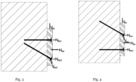
- Fig. 2 shows a cross-sectional view of a fastening of an attachment 10 using two anchors 14 in a near-edge area of a concrete base 12.
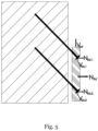
- Fig. 4 shows an alternative variant, the situation of Fig. 2
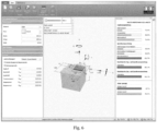
- FIG. 6 Another aspect of the present invention relates to a computer program product containing a plurality of instructions which, when executed on a computer system, output a GUI via a display device, as exemplified in Fig. 6 is shown.
- Such computer programs are generally known and common and help the user determine whether a planned application, in this case the fastening of a fixture 10 to a concrete base 12, complies with the design regulations.
- the GUI contains input fields that allow the user to enter information regarding a variety of characteristics, for example, a field 20 for specifying the base (in this case, concrete), a field 22 for entering information regarding the type, size, shape, and material of an anchor plate, fields 24 for entering design values of the loads, in particular tensile force, shear force, torsional moment, and bending moment, and a field 26 for specifying the type and dimensions of the anchor 14.
- a field 20 for specifying the base in this case, concrete
- a field 22 for entering information regarding the type, size, shape, and material of an anchor plate
- fields 24 for entering design values of the loads, in particular tensile force, shear force, torsional moment, and bending moment
- a field 26 for specifying the type and dimensions of the anchor 14.
- the results of the design calculation are displayed according to the entered values and parameters.
- the planned fastening meets the design requirements with regard to all failure mechanisms considered here with regard to tensile loading (steel failure, pull-out, concrete cone failure).
- the design requirements with regard to shear loading with regard to steel failure without lever arm and with regard to concrete cone failure are also met, but not with regard to failure with regard to concrete edge failure.
- the shear loading exceeds the resistance to shear loading with regard to the concrete edge cone failure mechanism by approximately 20%, and the interaction condition is even exceeded by 60%.
- the computer program can also suggest designs where the anchor is not set vertically, but at an angle ⁇ anchor to the surface normal of the fastening base 12.
- the program automatically suggests a design for an inclined installation if certain criteria are met.
- One such criterion may be that the design regulations cannot be met with a vertical installation of the anchor.
- Another criterion may be that a significantly better load-bearing capacity can be expected with an inclined installation, for example in cases where a limit for the ratio V Sd /N Sd is exceeded, or a limit for V Rk /N Rk is undercut.
- the computer program can also itself suggest the suitable, usually most cost-effective, anchors with which the fastening can be realized, taking advantage of the possibility of an inclined installation.
- FIG. 6 The screenshot shows that at an anchor angle ⁇ of 34.23°, the design requirements are not yet met, but the load-bearing capacity is already significantly better than with vertical installation. At an angle of 38°, however, all design requirements are met.
- the computer program can be provided to only perform a design for a predetermined alternative standard mounting angle, for example a mounting angle of 45°.
- the design can be carried out on request, i.e. in response to user input, and/or automatically.
- Automatic execution is considered, for example, if, due to the installation position (near the edge, lever arm, etc.) and the loads underlying the design, in particular tensile force and shear force, there are indications that the load-bearing capacity would be increased if installed using the alternative standard mounting angle compared to vertical installation. It is also possible to generally perform the design calculation for installation using the alternative standard mounting angle and display the result, or at least display it if it promises an improved load-bearing capacity.
- anchor is to be understood broadly and can be formed by a one-piece anchor in the narrowest sense as well as by two- or three-piece systems, which are briefly described below.
- the anchors 14 are each formed by concrete screws. Such concrete screws are known in the art and typically have a self-tapping concrete thread that forms a load introduction area, a shank portion, and a head that serves both as a power drive to set the anchor and to secure the attachment 10.
- Fig. 7 shows another example of a one-piece anchor, namely an undercut anchor that is inserted at an angle into the fastening base 12.
- the undercut anchor has a metric thread 28, onto which a washer 30 is placed, and which is tightened against the attachment 10 with a nut 32.
- Fig. 8 shows a two-part anchor comprising an anchor sleeve 34, which also provides an undercut.
- the anchor sleeve 34 is in Fig. 8 shown partially in section, and has a metric internal thread into which a threaded rod 36 is screwed.
- a washer 30 and a nut 32 are arranged.
- Fig. 9 shows a further example of a two-part anchor, comprising an anchor sleeve 40 with a self-tapping external thread 38.
- a metric internal thread is formed, into which, as in Fig. 8 a threaded rod 36 is screwed in.
- a washer 30 and a nut 32, which are tightened against the attachment 10, are used to fasten the attachment 10 to the mounting base 12.
- the threaded rod 36 represents an example of a "tensioning element" mentioned above.
- the anchor sleeve 40 also has a power drive (not shown in the figure) with which it can be screwed into the concrete of the mounting base 12.
- Fig. 10 shows an anchor 14 according to a related embodiment, which is formed by a three-part system comprising a first threaded sleeve 40 of the type described above and a second threaded sleeve 42 which does not contain an internal thread.
- the attachment 10 is also a concrete part that is joined to the base 12 by means of the anchor 14.
- An example of such concrete attachments are bridge caps or similar.
- the first threaded sleeve 40 is screwed into the fastening base 12, while the second anchor sleeve 42 is screwed into the attachment 10.
- the tensioning element here is again a threaded rod 36, which is guided through the (internally thread-free) second anchor sleeve 42 and screwed into the internal thread in the first anchor sleeve 40.
- the first and second anchor sleeves 40, 42 are axially tensioned such that the first and second anchor sleeves 40, 42 form opposing bond stresses in the fastening base 12 and the attachment 10, respectively.
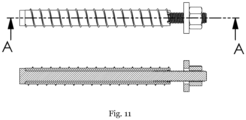
- Fig. 11 shows a side view and a sectional view of an alternative two-part system, which is similar to the system of the anchor 14 of Fig. 9 is fundamentally similar.
- the anchor sleeve 40 in this case does not have an internal thread
- the tensioning element in this case is formed by a screw 44 , which is to be inserted upside down, i.e. with the head 46 facing forward, into the borehole before the anchor sleeve 40 is screwed in.
- the head 46 is then located at the leading end of the tensioning element 44 and forms a stop element against which the anchor sleeve 40 can strike in order to transfer a load.
- This variant is advantageous in that the anchor sleeve 40 can be designed without an internal thread.
- a clamping element 44 can be used with a stop element 46 at the leading end, wherein again the clamping element 44 is first introduced into the borehole, and then the first and second sleeves 40, 42 are guided over the clamping element and screwed into the fastening base 12 and the attachment part 10, respectively.
- Example 7 Method according to one of the preceding examples, in which the said anchor (14) is an anchor closer to the edge within the anchor group, and the anchor group contains an anchor further from the edge which is inserted perpendicular to the surface of the fastening base (12).
- Example 18 A computer program product according to example 16 or 17, wherein the input fields of the GUI allow the user to enter information relating to one or more of the following characteristics: type or nature of the base material (12); type, size, shape and material of an anchor plate (10); design values relating to tensile force, shear force, torsional moment and/or bending moment; type and/or dimension of the anchor.
- Example 19 Computer program product according to one of examples 16 to 18, which is designed to first calculate a design for an anchor (14) set perpendicular to the anchoring base (12) and, in the event that this anchor does not meet the design requirements, to alternatively propose an inclined installation that meets the design requirements.
- Example 21 Process according to Example 20, wherein k ⁇ 1.2, preferably k ⁇ 1.15 and particularly preferably k ⁇ 1.1.
- Example 22 Process according to Example 20 or 21, wherein k ⁇ 0.85, preferably k ⁇ 0.9.
- Example 24 Method according to one of Examples 20 to 23, wherein the characteristic resistances under transverse stress V Rk and under tensile stress N Rk satisfy the following relationship: V Rk / N Rk ⁇ 1 , 0 , preferably ⁇ 0.8, and particularly preferably ⁇ 0.6.
- Example 25 Method according to one of examples 20 to 24, wherein the at least one anchor (14) is guided through a bore in the attachment part (10), wherein the diameter of the bore exceeds the diameter of the anchor (14) in a section in which it is in the mounted state in the borehole by less than 22%, preferably less than 12%.
- Example 26 Method according to one of examples 20 to 25, in which said anchor (14) is an anchor closer to the edge within the anchor group, and the anchor group contains an anchor further from the edge which is inserted perpendicular to the surface of the fastening base (12).
- Example 27 Method according to one of examples 20 to 26, in which the said anchor (14) is an anchor further from the edge within the anchor group, and the anchor group contains an anchor (14) closer to the edge, which is accommodated in a slot (16) in the attachment and is inserted perpendicular to the surface of the fastening base (12).
- Example 28 Method according to one of examples 20 or 22 to 27, in which there is an intermediate space between the attachment part (10) and the fastening base (12), in which space a non-compression-resistant material is located, and in which the following applies: k ⁇ 1.1, preferably k ⁇ 1.2 and particularly preferably k ⁇ 1.25.
- Example 29 Method for fastening attachments (10) to a fastening base (12) according to one of Examples 1 to 15, which includes a method for dimensioning this fastening according to one of Examples 20 to 28.
- Example 30 Method for fastening attachments (10) to a fastening base (12) according to Example 29, in which the dimensioning of this fastening is carried out using a computer program product according to one of Examples 16 to 19.
Landscapes
- Engineering & Computer Science (AREA)
- Architecture (AREA)
- General Engineering & Computer Science (AREA)
- Mechanical Engineering (AREA)
- Structural Engineering (AREA)
- Civil Engineering (AREA)
- Physics & Mathematics (AREA)
- Geometry (AREA)
- Electrochemistry (AREA)
- Chemical & Material Sciences (AREA)
- Chemical Kinetics & Catalysis (AREA)
- Theoretical Computer Science (AREA)
- General Physics & Mathematics (AREA)
- Mining & Mineral Resources (AREA)
- Electromagnetism (AREA)
- Mathematical Analysis (AREA)
- Pure & Applied Mathematics (AREA)
- Human Computer Interaction (AREA)
- Computational Mathematics (AREA)
- Evolutionary Computation (AREA)
- Computer Hardware Design (AREA)
- Mathematical Optimization (AREA)
- General Life Sciences & Earth Sciences (AREA)
- Geology (AREA)
- Geochemistry & Mineralogy (AREA)
- Life Sciences & Earth Sciences (AREA)
- Joining Of Building Structures In Genera (AREA)
- Reinforcement Elements For Buildings (AREA)
- Mutual Connection Of Rods And Tubes (AREA)
- Piles And Underground Anchors (AREA)
- Surgical Instruments (AREA)
- Lining Or Joining Of Plastics Or The Like (AREA)
Applications Claiming Priority (3)
| Application Number | Priority Date | Filing Date | Title |
|---|---|---|---|
| DE102016125201.8A DE102016125201A1 (de) | 2016-12-21 | 2016-12-21 | System zum Fügen oder Armieren von Bauteilen |
| PCT/EP2017/084239 WO2018115364A1 (fr) | 2016-12-21 | 2017-12-21 | Procédé permettant de fixer des pièces rapportées à du béton ou à une maçonnerie |
| EP17825857.0A EP3365564B1 (fr) | 2016-12-21 | 2017-12-21 | Procédé permettant de fixer des pièces rapportées à du béton ou à une maçonnerie |
Related Parent Applications (1)
| Application Number | Title | Priority Date | Filing Date |
|---|---|---|---|
| EP17825857.0A Division EP3365564B1 (fr) | 2016-12-21 | 2017-12-21 | Procédé permettant de fixer des pièces rapportées à du béton ou à une maçonnerie |
Publications (2)
| Publication Number | Publication Date |
|---|---|
| EP4542064A2 true EP4542064A2 (fr) | 2025-04-23 |
| EP4542064A3 EP4542064A3 (fr) | 2025-06-11 |
Family
ID=60937743
Family Applications (3)
| Application Number | Title | Priority Date | Filing Date |
|---|---|---|---|
| EP17826238.2A Active EP3559484B1 (fr) | 2016-12-21 | 2017-12-21 | Système d'assemblage ou de blindage de composants |
| EP25157145.1A Pending EP4542064A3 (fr) | 2016-12-21 | 2017-12-21 | Procédé pour fixer des éléments de fixation sur du béton ou sur un mur |
| EP17825857.0A Active EP3365564B1 (fr) | 2016-12-21 | 2017-12-21 | Procédé permettant de fixer des pièces rapportées à du béton ou à une maçonnerie |
Family Applications Before (1)
| Application Number | Title | Priority Date | Filing Date |
|---|---|---|---|
| EP17826238.2A Active EP3559484B1 (fr) | 2016-12-21 | 2017-12-21 | Système d'assemblage ou de blindage de composants |
Family Applications After (1)
| Application Number | Title | Priority Date | Filing Date |
|---|---|---|---|
| EP17825857.0A Active EP3365564B1 (fr) | 2016-12-21 | 2017-12-21 | Procédé permettant de fixer des pièces rapportées à du béton ou à une maçonnerie |
Country Status (7)
| Country | Link |
|---|---|
| US (4) | US11306496B2 (fr) |
| EP (3) | EP3559484B1 (fr) |
| CN (2) | CN110249142A (fr) |
| DE (1) | DE102016125201A1 (fr) |
| DK (1) | DK3559484T3 (fr) |
| ES (1) | ES2928225T3 (fr) |
| WO (2) | WO2018115364A1 (fr) |
Families Citing this family (14)
| Publication number | Priority date | Publication date | Assignee | Title |
|---|---|---|---|---|
| EP3388597A1 (fr) * | 2017-04-13 | 2018-10-17 | F.J. Aschwanden AG | Élément de renfort destiné à renforcer des plaques bétonnées |
| DE102020108557A1 (de) * | 2019-08-08 | 2021-02-11 | Ludwig Hettich Holding Gmbh & Co. Kg | System zum Befestigen eines Ankers in einem mineralischen Untergrund |
| CN111894148A (zh) * | 2020-06-23 | 2020-11-06 | 中铁第一勘察设计院集团有限公司 | 基于弹力圈承插的装配式预制墙板拼接件 |
| CN112572681A (zh) * | 2020-12-30 | 2021-03-30 | 玉环凯凌机械集团股份有限公司 | 一种高效制动中心阀 |
| CN112982686B (zh) * | 2021-01-26 | 2022-11-22 | 中国化学工程第三建设有限公司 | 一种梁柱钢筋接头处用预埋组件及方法 |
| CN113305983B (zh) * | 2021-06-15 | 2022-02-11 | 烟台聚通智能设备有限公司 | 一种生产加气板材的自动上扣系统 |
| CN113216639A (zh) * | 2021-06-17 | 2021-08-06 | 南京瑞平环境科技有限公司 | 一种拉结系统及拉结方法 |
| CN113931914B (zh) * | 2021-09-03 | 2023-06-09 | 深圳市艾比森光电股份有限公司 | 连接装置及显示屏 |
| CN113846855B (zh) * | 2021-10-14 | 2023-03-28 | 上海建工集团股份有限公司 | 一种预制构件快速吊装就位连接件 |
| CN114211764B (zh) * | 2021-12-14 | 2024-03-29 | 沈阳智勤机器人系统工程有限公司 | 一种适用于加气砖生产线网笼卡扣安装的自动化系统 |
| DE102022200441A1 (de) | 2022-01-17 | 2023-07-20 | Cbp Guideway Systems Gmbh | Verankerungseinheit zum Verankern in einem Bohrloch in einem Material, Verankerungsanordnung mit einer derartigen Verankerungseinheit und Verfahren zum Herstellen einer derartigen Verankerungsanordnung |
| DE102022200439A1 (de) | 2022-01-17 | 2023-07-20 | Cbp Guideway Systems Gmbh | Verankerungselement zum Verankern in einem Bohrloch, Verankerungsanordnung mit einem derartigen Verankerungselement und Verfahren zum Herstellen einer derartigen Verankerungsanordnung |
| CN116792038A (zh) * | 2022-11-10 | 2023-09-22 | 董泽兵 | 一种旋挖桩钻进装配式护筒及其使用方法 |
| CN118166927B (zh) * | 2024-01-26 | 2025-05-06 | 华南理工大学 | 带可替换耗能连接的x形支撑及其设计方法 |
Family Cites Families (66)
| Publication number | Priority date | Publication date | Assignee | Title |
|---|---|---|---|---|
| US1251676A (en) * | 1915-11-30 | 1918-01-01 | Hamilton Cassard | Screw-bushing for fastening boxes. |
| CH173307A (de) * | 1934-02-03 | 1934-11-30 | Kiefer Jacob | Schraubenverbindung, insbesondere für Doppelverglasungsfenster. |
| CH279221A (de) * | 1950-03-29 | 1951-11-30 | Fahrner Fritz | Verbindungsvorrichtung, insbesondere für Doppelverglasungsfenster. |
| US2639179A (en) * | 1950-03-31 | 1953-05-19 | Weber Knapp Co | Self-aligning, screw-threaded fastening device |
| GB1111587A (en) | 1965-09-07 | 1968-05-01 | Salvatore Vincent Giardiana | Load suspension apparatus |
| SE376040C (sv) * | 1968-12-16 | 1977-02-28 | R A R Johansson | Anordning for reglerbar infestning av element mot fasta element |
| US4022099A (en) | 1976-02-06 | 1977-05-10 | General Motors Corporation | Threaded fastener with reusable thread forming pilot tip |
| US4097061A (en) | 1976-04-19 | 1978-06-27 | Dietlein Robert W | Ski insert for anchoring a ski binding screw in a ski |
| DE2834200A1 (de) | 1978-08-04 | 1980-02-21 | Ross Kg Sued Ind Daecher Und F | Duebel |
| DE3000154C2 (de) * | 1980-01-04 | 1982-10-21 | Upat Gmbh & Co, 7830 Emmendingen | Vorrichtung zur Eintragung einer äußeren Last in bestehende Stahl- und Spannbetonbauteile und Verfahren zum Einbau dieser Vorrichtung |
| FR2520455B1 (fr) | 1982-01-25 | 1985-10-18 | France Etat | Procede et dispositifs d'assemblage d'elements en materiaux composites par des organes filetes |
| GB8333051D0 (en) | 1983-12-10 | 1984-01-18 | Sinclair A A | Bolt system |
| US4655656A (en) * | 1985-06-03 | 1987-04-07 | Ab Essve Produkter | Fastening device for door or window frames |
| US4730968A (en) | 1986-09-08 | 1988-03-15 | David Diperstein | Self-tapping, self-aligning thread repair insert |
| CH682940A5 (de) | 1990-09-20 | 1993-12-15 | Werner Flueckiger | Befestigungsvorrichtung. |
| DE9216965U1 (de) * | 1992-11-27 | 1993-04-22 | Kellner, Peter | Sicherungselement zur Befestigung von Fassadenplatten an Plattenbauwerken |
| DE19610267A1 (de) * | 1996-03-15 | 1997-09-18 | Pfleiderer Daemmstofftechnik G | Dachkonstruktion |
| DE29610381U1 (de) * | 1996-06-13 | 1996-09-05 | Bulldog-Simpson GmbH, 28857 Syke | Verbinder zum stirnseitigen Anschluß eines Balkens an ein Bauteil |
| RU2105847C1 (ru) * | 1996-06-27 | 1998-02-27 | Акционерное общество "Композит" | Устройство для крепления облицовочных плит |
| US5993129A (en) * | 1996-10-04 | 1999-11-30 | Kabushiki Kaisha Youma Kohboh | Bolt anchoring device with improved plug portion of bolt |
| US5961266A (en) * | 1998-06-11 | 1999-10-05 | Tseng; Shao-Chien | Anti-vibration bolt and nut structure |
| DE19830682A1 (de) * | 1998-07-09 | 2000-02-03 | Friedhelm Schlaf | Befestigungselement |
| JP3405932B2 (ja) | 1999-02-12 | 2003-05-12 | 株式会社ヤマヒロ | アンカーボルト及びその施工工具並びにその施工工具を用いたアンカーボルトの取付け施工方法 |
| DE10036754C1 (de) * | 2000-07-28 | 2002-06-13 | Gustav Bohrenkaemper | Verbindungsvorrichtung für zwei Bauteile |
| US6560940B2 (en) | 2000-08-18 | 2003-05-13 | Lee W. Mueller | Two-piece clinched plate tension/compression bracket |
| CA2388277C (fr) * | 2001-06-08 | 2006-10-31 | Illinois Tool Works Inc. | Ensemble d'anticheminant de metro |
| DE10246386B4 (de) | 2002-10-04 | 2008-08-07 | Biedermann Motech Gmbh | Knochenschraube, Knochenfixationseinrichtung und Halteelement |
| CN2632374Y (zh) | 2003-07-07 | 2004-08-11 | 袁锡锋 | 预埋板锚固螺栓 |
| DE102004033472A1 (de) | 2004-07-10 | 2006-01-26 | Fischerwerke Artur Fischer Gmbh & Co. Kg | Montageplatte zur Befestigung einer Markise an einer Hauswand mit einem Wärmedämmverbundsystem |
| CN2758549Y (zh) * | 2004-09-27 | 2006-02-15 | 群勃股份有限公司 | 一次攻钉的螺丝钉 |
| US20060067803A1 (en) * | 2004-09-27 | 2006-03-30 | Hsu Chin J | Self-drilling wall anchor device |
| DE102005007721B4 (de) * | 2005-02-18 | 2021-10-07 | Toge Dübel Gmbh & Co. Kg | Befestigungs-Anker sowie Anordnung desselben in einem porösen Werkstoff |
| US7752824B2 (en) * | 2005-03-14 | 2010-07-13 | Mitek Holdings, Inc. | Shrinkage-compensating continuity system |
| DE102005000108A1 (de) * | 2005-09-02 | 2007-03-15 | Hilti Ag | Befestigungselement für harte Untergründe |
| DE102005000110A1 (de) * | 2005-09-02 | 2007-03-08 | Hilti Ag | Befestigungselement für harte Untergründe |
| DE202006014469U1 (de) * | 2006-04-18 | 2007-01-18 | Ideematec Deutschland Gmbh | Befestigungsvorrichtung für Anlagen auf Dächern |
| US7658242B2 (en) * | 2006-01-17 | 2010-02-09 | Duncan C Warren | Hole coring system with lever arm |
| US7588402B2 (en) | 2006-08-31 | 2009-09-15 | Shu-Yun Chuang | Fastener with removable element |
| DE102006000486A1 (de) * | 2006-09-28 | 2008-04-10 | Hilti Ag | Ankerstab und Anordnung zum Verstärken von bestehenden Bauteilen gegen Durchstanzen mit einem solchen Ankerstab |
| DE202007007550U1 (de) * | 2007-05-25 | 2007-09-06 | MÖLLER, Olaf | Befestigungssystem zum Verbinden von Profilstäben |
| CL2008002711A1 (es) | 2007-09-14 | 2010-06-18 | Longyear Tm Inc | Dispositivo de anclaje de autoperforacion, que comprende una varilla de perforacion, una broca de barrena en un extremo de la varilla, un armazon de expansion adyacente a la broca y un manguito de varilla adyacente al armazon; metodo para montar y metodo para instalar dicho dispositivo de anclaje. |
| DE102007054798B3 (de) * | 2007-11-16 | 2009-04-16 | Ludwig Hettich & Co. | Verfahren zum Herstellen eines Gewindeeinsatzes mit Innen- und Außengewinde und Gewindeeinsatz |
| DE202008001661U1 (de) | 2008-02-06 | 2008-04-24 | Gebr. Dieterle GbR (vertretungsberechtige Gesellschafter: Frank Dieterle, 77761 Schiltach und Thomas Dieterle, 78739 Hardt) | Brücke oder Brückenabschnitt |
| DE102008016866B4 (de) | 2008-04-02 | 2011-04-28 | Ludwig Hettich & Co. | Gewinde furchende Schraube |
| DE102008049640A1 (de) * | 2008-09-30 | 2010-04-01 | Flückiger, Werner | Befestigungselement |
| DE102009022161A1 (de) * | 2009-05-20 | 2010-12-09 | Rensburg, Markus, Dipl.-Wirtsch.-Ing. | Befestigungselement für Dachaufbauten, insbesondere Solaranlagen, Dachaufbauten mit einem derartigen Befestiger und Verfahren zum Verbinden eines Dachaufbaus mit einem Dach |
| DE102010014318A1 (de) * | 2010-04-09 | 2011-10-13 | Siemens Aktiengesellschaft | Befestigungseinrichtung zum kraftschlüssigen Verbinden zweier Werkstücke sowie Verwendung einer Befestigungseinrichtung |
| DE102011002637A1 (de) | 2011-01-13 | 2012-07-19 | Hilti Aktiengesellschaft | Schraubanker und Verfahren zur Herstellung eines Schraubankers |
| DE102011006015A1 (de) * | 2011-03-24 | 2012-09-27 | Hilti Aktiengesellschaft | Gewindeschneidsystem |
| CN102182737B (zh) * | 2011-06-10 | 2013-06-19 | 温少松 | 隐形紧压拉爆螺丝 |
| DE102011077595A1 (de) | 2011-06-16 | 2012-12-20 | Hilti Aktiengesellschaft | Ankerschraube |
| US8950130B2 (en) * | 2011-09-30 | 2015-02-10 | John Daines Chadwick | Techniques for building construction using fabricated timbers |
| CN202612315U (zh) * | 2012-05-23 | 2012-12-19 | 赵军伟 | 一种双向膨胀螺栓 |
| DE102012108779A1 (de) * | 2012-09-18 | 2014-04-10 | Hartmut Flaig | Profilverbindung |
| NL2010093C2 (en) * | 2013-01-08 | 2014-07-09 | Es | Wall assembly, cladding panel support beam, anchor guide, kit of parts and method for cladding a wall. |
| JP2014145154A (ja) * | 2013-01-28 | 2014-08-14 | Systec:Kk | 後施工曲折アンカーボルトとその施工方法 |
| DE102013203150A1 (de) | 2013-02-26 | 2014-08-28 | Hilti Aktiengesellschaft | Verfahren zum Herstellen einer Betonschraube |
| DE102013109428A1 (de) * | 2013-05-02 | 2014-11-06 | Ludwig Hettich & Co. Kg | Verankerungssystem |
| DE102013104478A1 (de) | 2013-05-02 | 2014-11-06 | Ludwig Hettich & Co. Kg | Verankerungssystem |
| DE102013106428A1 (de) | 2013-06-20 | 2014-12-24 | Fischerwerke Gmbh & Co. Kg | Montageplatte zur Befestigung eines Bauteils an einer Wand |
| DE102013109987B4 (de) | 2013-09-11 | 2017-03-23 | Ludwig Hettich Holding Gmbh & Co. Kg | Wendel für einen Gewindeeinsatz |
| DE202013105729U1 (de) * | 2013-12-17 | 2015-03-18 | Heim & Haus Holding Gmbh | Befestigungsvorrichtung zum Überbrücken einer nicht tragenden Wandschicht |
| DE102014109329A1 (de) * | 2014-07-03 | 2016-01-07 | Monier Roofing Components Gmbh | Befestigungsvorrichtung zur Befestigung von Dachaufbauten an einem Steildach |
| DE102015213869A1 (de) * | 2015-07-22 | 2017-01-26 | Prof. Feix Research & Development Gmbh & Co. Kg | Verstärkungselement zum Verstärken eines Bauelements, Verstärkungsanordnung umfassend ein derartiges Verstärkungselement sowie Verfahren zum Verstärken eines Bauelements |
| CN204876768U (zh) * | 2015-08-29 | 2015-12-16 | 徐毓艺 | 组合串联电杆 |
| US10935067B2 (en) | 2018-08-21 | 2021-03-02 | Max Gripp Anchors, Llc | Reverse-thread insert anchor for masonry applications |
-
2016
- 2016-12-21 DE DE102016125201.8A patent/DE102016125201A1/de not_active Ceased
-
2017
- 2017-12-21 WO PCT/EP2017/084239 patent/WO2018115364A1/fr not_active Ceased
- 2017-12-21 CN CN201780085531.7A patent/CN110249142A/zh active Pending
- 2017-12-21 DK DK17826238.2T patent/DK3559484T3/da active
- 2017-12-21 WO PCT/EP2017/084230 patent/WO2018115358A2/fr not_active Ceased
- 2017-12-21 EP EP17826238.2A patent/EP3559484B1/fr active Active
- 2017-12-21 ES ES17826238T patent/ES2928225T3/es active Active
- 2017-12-21 EP EP25157145.1A patent/EP4542064A3/fr active Pending
- 2017-12-21 US US16/472,080 patent/US11306496B2/en active Active
- 2017-12-21 EP EP17825857.0A patent/EP3365564B1/fr active Active
- 2017-12-21 CN CN201780085224.9A patent/CN110234893A/zh not_active Withdrawn
- 2017-12-21 US US16/472,114 patent/US20200208422A1/en not_active Abandoned
-
2022
- 2022-04-14 US US17/720,471 patent/US20230358063A1/en active Pending
- 2022-07-15 US US17/865,512 patent/US12110699B2/en active Active
Also Published As
| Publication number | Publication date |
|---|---|
| CN110234893A (zh) | 2019-09-13 |
| EP4542064A3 (fr) | 2025-06-11 |
| US20230358063A1 (en) | 2023-11-09 |
| US12110699B2 (en) | 2024-10-08 |
| US20230022176A1 (en) | 2023-01-26 |
| DK3559484T3 (da) | 2022-10-24 |
| EP3365564C0 (fr) | 2025-02-12 |
| WO2018115358A2 (fr) | 2018-06-28 |
| EP3559484A2 (fr) | 2019-10-30 |
| US11306496B2 (en) | 2022-04-19 |
| WO2018115364A1 (fr) | 2018-06-28 |
| EP3365564A1 (fr) | 2018-08-29 |
| EP3365564B1 (fr) | 2025-02-12 |
| ES2928225T3 (es) | 2022-11-16 |
| WO2018115358A3 (fr) | 2018-08-30 |
| DE102016125201A1 (de) | 2018-06-21 |
| EP3559484B1 (fr) | 2022-07-20 |
| CN110249142A (zh) | 2019-09-17 |
| US20200224439A1 (en) | 2020-07-16 |
| US20200208422A1 (en) | 2020-07-02 |
Similar Documents
| Publication | Publication Date | Title |
|---|---|---|
| EP3365564B1 (fr) | Procédé permettant de fixer des pièces rapportées à du béton ou à une maçonnerie | |
| DE19947913C2 (de) | Befestigungselement zur Anbringung von Lasten an eine eine Wärmedämmung aufweisende Gebäudewand | |
| EP1899613B1 (fr) | Vis d'ancrage | |
| EP2715156A1 (fr) | Système de fixation d'une façade isolante et dispositif de fixation prévu à cet effet | |
| EP2206931B1 (fr) | Vis et son utilisation | |
| EP2715013A1 (fr) | Ensemble d'assemblage et procédé de production d'une consolidation contre la perforation, d'un renfort de force transversale supplémentaire ou d'un raccordement d'armature | |
| EP0988430B1 (fr) | Panne de couplage constituee de deux ou plusieurs poutres en bois jointes l'une a l'autre par chevauchement longitudinal, ainsi qu'element de fixation pour relier deux zones d'extremite se chevauchant de poutres en bois a utiliser pour une panne de couplage | |
| EP3144448B1 (fr) | Plaque de montage destinée à fixer un composant sur un mur | |
| DE102012211638A1 (de) | Verankerungssystem | |
| DE102019114492A1 (de) | Befestigungssystem mit Kraftverteilung | |
| DE102023111184A1 (de) | Verstärkung für einen Porenbetonträger, Porenbetonträger, Verwendung eines Porenbetonträgers, Verfahren zum Verstärken eines Porenbetonträgers und Verwendung einer Verstärkung | |
| EP3839162B1 (fr) | Composant thermo-isolant destiné à être utilisé dans une fente de séparation entre deux parties de construction | |
| EP3173632A1 (fr) | Ancrage pour béton, système d'ancrage pour béton, système de fixation et procédé de fabrication d'un système de fixation | |
| EP1847666A1 (fr) | Dispositif d'ancrage pour lier des planches de coffrage | |
| EP3091167A1 (fr) | Élément de fixation pour un cadre de fenêtre sur un plafond de bâtiment d'une construction, construction associée et procédé de fixation d'un cadre de fenêtre sur un plafond de bâtiment | |
| DE102013104478A1 (de) | Verankerungssystem | |
| WO2005042987A1 (fr) | Element de fixation | |
| DE3834731A1 (de) | Vorrichtung zur verankerung oder verbindung von betonbewehrungsstaeben sowie verfahren zum herstellen derselben | |
| DE10161426A1 (de) | Verankerung für verspannte Konstruktionen | |
| EP2182125A2 (fr) | Procédé de fixation d'éléments de construction dans un intervalle par rapport à un composant | |
| DE102024124235A1 (de) | Montageelement für den Holz- und Hochbau | |
| EP4339383A1 (fr) | Dispositif de liaison pour la liaison de transmission de force d'une première partie de construction absorbant de force à une seconde partie de construction absorbant de force et construction | |
| DE2406913A1 (de) | Ankerelement fuer poroese materialien, wie gasbeton o.dgl. | |
| DE202021101485U1 (de) | Zarge-Lichtschachtsystem | |
| DE202004005069U1 (de) | Verbindungselement zur Verbindung von Stahlbeton- bzw. Stahlteilen im Montagebau |
Legal Events
| Date | Code | Title | Description |
|---|---|---|---|
| PUAI | Public reference made under article 153(3) epc to a published international application that has entered the european phase |
Free format text: ORIGINAL CODE: 0009012 |
|
| STAA | Information on the status of an ep patent application or granted ep patent |
Free format text: STATUS: THE APPLICATION HAS BEEN PUBLISHED |
|
| AC | Divisional application: reference to earlier application |
Ref document number: 3365564 Country of ref document: EP Kind code of ref document: P |
|
| AK | Designated contracting states |
Kind code of ref document: A2 Designated state(s): AL AT BE BG CH CY CZ DE DK EE ES FI FR GB GR HR HU IE IS IT LI LT LU LV MC MK MT NL NO PL PT RO RS SE SI SK SM TR |
|
| PUAL | Search report despatched |
Free format text: ORIGINAL CODE: 0009013 |
|
| AK | Designated contracting states |
Kind code of ref document: A3 Designated state(s): AL AT BE BG CH CY CZ DE DK EE ES FI FR GB GR HR HU IE IS IT LI LT LU LV MC MK MT NL NO PL PT RO RS SE SI SK SM TR |
|
| RIC1 | Information provided on ipc code assigned before grant |
Ipc: F16B 13/00 20060101AFI20250502BHEP |
|
| STAA | Information on the status of an ep patent application or granted ep patent |
Free format text: STATUS: REQUEST FOR EXAMINATION WAS MADE |
|
| 17P | Request for examination filed |
Effective date: 20251211 |