EP4544962A1 - Meuble d'assise - Google Patents
Meuble d'assise Download PDFInfo
- Publication number
- EP4544962A1 EP4544962A1 EP23206046.7A EP23206046A EP4544962A1 EP 4544962 A1 EP4544962 A1 EP 4544962A1 EP 23206046 A EP23206046 A EP 23206046A EP 4544962 A1 EP4544962 A1 EP 4544962A1
- Authority
- EP
- European Patent Office
- Prior art keywords
- headrest
- guide
- seating furniture
- backrest
- pivot axis
- Prior art date
- Legal status (The legal status is an assumption and is not a legal conclusion. Google has not performed a legal analysis and makes no representation as to the accuracy of the status listed.)
- Pending
Links
Images


Classifications
-
- A—HUMAN NECESSITIES
- A47—FURNITURE; DOMESTIC ARTICLES OR APPLIANCES; COFFEE MILLS; SPICE MILLS; SUCTION CLEANERS IN GENERAL
- A47C—CHAIRS; SOFAS; BEDS
- A47C7/00—Parts, details, or accessories of chairs or stools
- A47C7/36—Supports for the head or the back
- A47C7/38—Supports for the head or the back for the head, e.g. detachable
-
- A—HUMAN NECESSITIES
- A47—FURNITURE; DOMESTIC ARTICLES OR APPLIANCES; COFFEE MILLS; SPICE MILLS; SUCTION CLEANERS IN GENERAL
- A47C—CHAIRS; SOFAS; BEDS
- A47C7/00—Parts, details, or accessories of chairs or stools
- A47C7/36—Supports for the head or the back
- A47C7/40—Supports for the head or the back for the back
- A47C7/402—Supports for the head or the back for the back adjustable in height
Definitions
- the invention relates to a piece of seating furniture with at least one headrest which can be moved between a storage position and a use position.
- the invention relates to the field of upholstered furniture, i.e. armchairs and sofas which are partially or largely completely covered with a textile cover and at least partially provided with upholstery.
- Such furniture is particularly popular in living rooms, and it's desirable for the furniture to have an attractive appearance when not in use.
- a headrest which can significantly improve comfort when the piece is in use, can be aesthetically unattractive when not in use.
- the object of the invention is to provide a piece of seating furniture with a headrest, the headrest of which is designed and/or mechanically connected in such a way that it allows comfortable use and aesthetically pleasing storage when not in use.
- a piece of seating furniture which, in accordance with the known prior art, has a seat and a backrest and which further has at least one headrest that can be moved relative to the backrest between a storage position and a use position.
- a sofa preferably several, and in particular two, such headrests are provided, which can be moved independently of one another into the use position and the storage position.
- the headrest In the use position, the headrest is in a position in which a headrest contact surface is substantially aligned with a backrest contact surface of the backrest.
- Such an aligned arrangement means that the contact surfaces are oriented relative to one another in such a way that comfortable sitting with the back and head resting is possible.
- An aligned arrangement within the meaning of the invention does not mean an arrangement that is precisely aligned in the geometric sense.
- the headrest In the stowed position, the headrest is lowered compared to the use position.
- the headrest can remain visible from the outside in the use position.
- designs are also possible in which the headrest is housed in a compartment visible from the outside in the stowed position.
- first guide tab and at least one second guide tab are provided.
- the two guide tabs form rigid and preferably metallic elements that are attached to the backrest and the headrest so they can pivot about different axes.
- the first guide tab is attached to the backrest so it can pivot about a first pivot axis and is attached to the headrest so it can pivot about a third pivot axis.
- the second guide tab is attached to the backrest so it can pivot about a second pivot axis and is attached to the headrest so it can pivot about a fourth pivot axis.
- first guide tabs and/or two second guide tabs are usually provided for each headrest, with one first guide tab and one second guide tab being assigned to the left end of the headrest, and one first guide tab and one second guide tab being assigned to the right end of the headrest.
- the first or the second guide tabs are connected to one another by means of a torsion member, so that the first guide tabs on both sides or the second guide tabs on both sides always move together.
- the first and the second guide tab are preferably each provided in duplicate, this does not necessarily and preferably does not apply to the other elements of the mechanism described below, in particular not to the motor described below, as well as the drive lever and the securing member.
- the distance between the first and the third pivot axis of the first guide bracket, the distance between the second and the fourth pivot axis of the second guide brackets as well as the distance between the first and second pivot axes on the backrest and the distance between the third and fourth pivot axes on the headrest are selected such that the headrest is pivoted by less than 20° in the use position compared to the stowed position.
- the swivel angle of the headrest is preferably even smaller, in particular preferably less than 10° or ideally 0°.
- a headrest that remains largely or completely consistent in its orientation when transferred from the stowed position to the use position and that is relocated in this approximately or completely consistent orientation between the stowed position and the use position.
- the headrest's head support surface is typically largely vertical in the use position and, due to this largely consistent orientation, is also at least substantially vertical in the stowed position.
- This alignment allows for a desirable shallow backrest depth, since, unlike conventional designs, it does not have to accommodate a headrest tilted horizontally. It can also be provided that the headrest retracts into a concealed storage space in the stowed position.
- the essentially vertical position in the stowed position is also advantageous in such a configuration, since the storage space can also be primarily vertically oriented and thus does not unacceptably increase the overall depth of the seating furniture.
- the headrest is visible from the outside in the stowed position, but fits flush with the rear structure of the backrest.
- a rear side opposite the headrest surface forms part of the rear end surface of the seating furniture in the stowed position.
- the back of the headrest can protrude no more than 20 mm beyond this closing surface in relation to the longitudinal direction of the furniture in the stowed position, or be set back more than 20 mm from this end surface, so that it forms an approximately uniform rear side of the piece of furniture with the surrounding end surface.
- the size of the recess is preferably adapted to the size of the headrest.
- the recess is preferably adapted to the shape of the headrest in such a way that the headrest, in the stowed position, fills at least 90% of the volume of the recess.
- a power source such as a spring is preferably provided to assist the movement of the headrest.
- a locking mechanism in the use position is also useful in such a manual concept.
- a motor which could be designed as a spring motor, but is preferably an electric motor.
- the motor can be designed as a linear motor with a linearly extendable output member. This output member can act directly on one of the guide plates, thereby pivoting it.
- a preferred design is one in which a drive lever is interposed which can be pivoted by means of the electric motor and which in turn acts directly or indirectly on one of the guide tabs and thereby displaces the headrest and the other guide tab.
- the interposition of the drive lever is particularly useful when a large pivot angle of both guide tabs between the stowed position and the use position is required.
- This pivot angle is preferably > 120°, especially > 130°, since such a large angle allows for a large spacing of the headrest in the stowed position and the use position.
- Such a swivel angle can be achieved by directly connecting the linearly extendable output link.
- this is not considered an optimal solution, as it requires a more powerful motor due to the unfavorable angles at the beginning and end of the movement.
- the movement profile is unfavorable.
- the angular velocity of the headrest increases before reaching the use position. There is a risk that the headrest could strike the back of a person's head at a relatively high speed.
- the interposition of the drive lever results in a different movement profile and, in particular, enables the targeted influencing of the movement profile. It can be provided that the drive lever sweeps over a comparatively small angle of preferably less than 120° and, in particular, preferably between 75° and 110°, so that a roughly constant speed is achieved during this process, and that, by amplifying the movement, the guide plate sweeps over an angle of more than 120°, in particular an angle between 130° and 150°.
- One possibility for connecting the drive lever and guide plate is an intermediate plate that is pivotally connected to the drive lever and the guide plate.
- a design that has proven structurally advantageous is one in which a guide track is provided on the drive lever or the guide plate, in or along which a guide slider or a guide roller, which is attached to the other component, can move.
- a guide can be formed by a sliding edge or a rolling edge.
- it is a circumferentially closed structure such as an elongated hole. Even more complex shapes than a linear elongated hole are possible and allow the implementation of various movement sequences.
- the distance between the guide slider or guide roller and the pivot axis of the drive lever is at least temporarily and preferably at all times during the transfer of the headrest from the stowed position to the use position greater than the distance between the guide slider or guide roller and the backrest-side pivot axis of the guide bracket driven by the drive lever.
- the guide track is preferably provided on the drive lever.
- the guide slider or preferably the guide roller is preferably provided on the guide bracket.
- the link is arranged in such a way that during the pivoting of the guide plate from the storage position into the use position, the link slider or the link roller are displaced in a first direction along the link track in a first phase and are displaced again in the opposite direction towards the starting position in a further second phase.
- the opposing edges of the quadrilateral deviate from each other in terms of their length by no more than 10%, preferably by no more than 5%.
- a design in which opposing edges are almost identical ( ⁇ 1% deviation) is particularly preferred. This leads to a purely parallel displacement of the headrest.
- a headrest can thus be designed such that its alignment is purely vertical or almost vertical in the stowed position and the use position.
- connecting lines between the first and second pivot axes and between the third and fourth pivot axes each enclose an angle of less than 10°, preferably an angle of less than 5°, with connecting lines between the first pivot axis and the third pivot axis and between the second pivot axis and the fourth pivot axis.
- this angle can also be 0°, which means that all four horizontal pivot axes lie on one, in particular vertical, line.
- a securing member which, in the aforementioned extended configuration, prevents the guide plates from flipping over into a crossing configuration.
- the simplest way to achieve this is with a securing member in the form of a connecting plate, which is pivotally attached to the first guide plate and the second guide plate. These can be fixed and defined pivot axes. If the rectangle is not a parallelogram, a pivot axis can also have limited mobility. Such a securing member prevents the aforementioned flipping over into a crossed position.
- pivot axes of the securing link are offset from the respective connecting line between the two other pivot axes of the respective guide bracket, in particular offset from this imaginary line by at least 20 mm, preferably by at least 40 mm.
- a first guide tab and a second guide tab are preferably provided at each end of the headrest. It is preferably provided that the two guide tabs are sufficiently spaced from each other on each side to reduce the risk of crushing. In particular, it can be provided that the first guide tab and the second guide tab are spaced from each other by at least 10 mm, preferably at least 18 mm, in a transverse direction of the furniture. Alternatively, it can also be provided that the guide tabs are spaced significantly further from each other. For example, a design is also possible in which two first guide tabs are provided and only one second guide tab. In this case, the second guide tab can be provided centrally. Furthermore, a design is possible in which both guide tabs are provided approximately centrally. It is even possible to provide only a first and a second guide tab, which are designed to be sufficiently stable in terms of shape and, in particular, material thickness.
- guide tabs are located near the end of a headrest, it may be advantageous to attach them to a side surface of the headrest so that they can pivot and are visible. This ensures high stability of the headrest against unwanted pivoting movement around a vertical axis. Furthermore, it prevents the headrest from being slit.
- Other guide tabs can be pivotally connected in an interior space of the headrest surrounded by outer surfaces of the headrest, wherein in particular preferably a slot is provided in the outer surface of the headrest for the passage of this other guide tab.
- the pivot axes are also preferably arranged within an interior space, so that slots may be required to guide the guide tabs to the outside.
- the guide tabs it is preferable for the guide tabs to extend over the backrest from behind. Ideally, this eliminates the need for a slot in the top of the backrest.
- the at least one guide tab preferably has a curved shape, with a tab section at least 12 cm long.
- this tab section extends from the rear over one upper end surface of the backrest and forms an angle of no more than 30° with a horizontal plane.
- both guide tabs are designed in this manner.
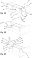
- Fig. 1 to 3 show a piece of seating furniture 10, which is designed as a sofa and has two headrests 30 constructed according to the invention.
- the sofa design is purely exemplary. A design as an armchair with only one headrest is also possible.
- the piece of seating furniture 10 has a base 12 for stationary or, in the case of an armchair, rotatable installation.
- a backrest 16 is provided behind a seat 14, the backrest being designed to be Fig. 1 to 3 from a rear wall 16A and back cushions 16B. An integrated design without separate back cushions 16B is also possible.
- Recesses or depressions 17 are provided in the rear wall 16A to accommodate the headrests 30 when they are in an unused stowed position. From this stowed position, the headrests can be transferred separately into a use position, as the sequence of Fig. 1 to 3 shows.
- the headrests are displaced by means of two first guide plates 44 and two second guide plates 46.
- the specific design of the guide plates 44, 46 and the driving of the guide plates will be explained below.
- the first guide tabs 44 form the outer guide tabs, which are pivotally connected to side surfaces 36.
- the second guide tabs 46 in contrast, form inwardly offset guide tabs, the articulation of which on the headrest 30 takes place in an interior region of the headrest 30 and is therefore not visible from the outside.
- the guide tabs 44, 46 are spaced apart from one another, preferably by approximately 20 mm to 30 mm, in order to avoid the risk of something, in particular a person's finger, becoming trapped between the guide tabs 44, 46.
- Figures 2A to 4D illustrate the mechanism by which the headrest 30 is guided and driven.
- Fig. 2A and 2B the headrest 30 in its stowed position according to the Fig. 1A .
- the Fig. 4A and 4B show the headrest 30 in the use position according to the Fig. 1C .
- the Fig. 3A and 3B illustrate an intermediate state that is similar to that of Fig. 1B corresponds.
- each headrest comprises two first guide tabs 44 and two second guide tabs 46.
- the two guide tabs 44, 46 are pivotally mounted on the backrest 16, with the respective pivot axes 44A, 46A located within the rear wall 16A and thus not visible from the outside. Attachment to the backrest 16 is achieved by means of a fitting plate (not specified in more detail), which may be attached to an internal frame of the piece of furniture.
- the two pivot axes 44A and 46A are vertically offset from one another.
- the distance and relative orientation of the pivot axes 44A and 46A to one another corresponds to the distance and orientation of the pivot axes 44B, 46B, about which the guide tabs 44, 46 are pivotally mounted on the headrest.
- the distance between the two pivot axes 44A, 44B of the first guide tab 44 corresponds to the distance between the two pivot axes 46A, 46B of the second guide tab.
- the pivot axes 44A, 44B, 46A, 46B are thus arranged in a parallelogram configuration. This achieves the parallel displacement explained above.
- Both guide tabs 44, 46 have a rearwardly sloping orientation. This means that the pivot axes 44B, 46B are each arranged below the pivot axes 44A, 44B.
- the guide tabs 44, 46 pivot when the headrest is transferred into the use position according to Fig. 4B by approximately 135°. This allows the headrest 30 to initially be raised largely vertically and then displaced forward over an upper end surface 22 of the backrest 16, so that in the use position it assumes a substantially flush arrangement relative to a backrest support surface, thus enabling a normal sitting position with the head leaning back.
- an electric motor 80 does not act directly on one of the guide tabs.
- an electric motor 80 is provided to first actuate a drive lever 60, which then in turn drives the guide bracket 46.
- the drive lever 60 like the guide brackets 44, 46, is pivotably connected to the backrest or the fitting plate thereon about a pivot axis 60A.
- a linearly movable output member 82 of the electric motor 80 is pivotally connected to the drive lever 60 about a pivot axis 82A. If the output member 82 is extended, the drive lever 60 pivots. As can be seen from the sequence of Fig. 2 to 4 As can be seen, the drive lever pivots by about 90°.
- the pivoting movement of the drive lever 60 is used to drive the guide plate 46.
- the drive lever 60 has a guide track in the form of an elongated hole 62.
- a guide roller 47 is guided in this elongated hole 62 and is rotatably attached to the guide plate 46.
- Fig. 2B The position of the cam roller 47 is indicated by a reference symbol. However, the cam roller 47 itself is not visible here, as it is concealed by the connecting tab 70, which will be described below.
- the intermediate position is problematic with a pure parallelogram, as the system cannot absorb forces perpendicular to the imaginary line crossed by all four pivot axes. Thus, in the case of the headrest, it cannot absorb forces acting on the headrest from the front. Even if the angle is not 0°, but below 20°, stability is noticeably limited.
- the fitting has the already mentioned connecting bracket 70.
- the pivot axes 70A, 70B are offset in the intermediate position mentioned by at least 20 mm and in this case by more than 40 mm relative to an imaginary connecting line between the pivot axes 44A, 44B, 46A, 46B.
- the continued movement therefore takes place safely beyond this intermediate position until the state of Fig. 4A and 4B and the use position of the headrest 30 achieved here.
- the headrest is now aligned with the front contact surface of the backrest and is suitable for safely and stably transferring the forces acting on it to the guide tabs and via them into the backrest.
Landscapes
- Chair Legs, Seat Parts, And Backrests (AREA)
Priority Applications (1)
| Application Number | Priority Date | Filing Date | Title |
|---|---|---|---|
| EP23206046.7A EP4544962A1 (fr) | 2023-10-26 | 2023-10-26 | Meuble d'assise |
Applications Claiming Priority (1)
| Application Number | Priority Date | Filing Date | Title |
|---|---|---|---|
| EP23206046.7A EP4544962A1 (fr) | 2023-10-26 | 2023-10-26 | Meuble d'assise |
Publications (1)
| Publication Number | Publication Date |
|---|---|
| EP4544962A1 true EP4544962A1 (fr) | 2025-04-30 |
Family
ID=88558466
Family Applications (1)
| Application Number | Title | Priority Date | Filing Date |
|---|---|---|---|
| EP23206046.7A Pending EP4544962A1 (fr) | 2023-10-26 | 2023-10-26 | Meuble d'assise |
Country Status (1)
| Country | Link |
|---|---|
| EP (1) | EP4544962A1 (fr) |
Citations (2)
| Publication number | Priority date | Publication date | Assignee | Title |
|---|---|---|---|---|
| DE202007018353U1 (de) * | 2007-04-20 | 2008-06-12 | Hukla Möbel GmbH | Sitzmöbel |
| DE202011102686U1 (de) * | 2011-07-05 | 2011-11-29 | Stanzwerk Wetter Sichelschmidt Gmbh & Co. Kg | Kombinations-Sitzmöbel |
-
2023
- 2023-10-26 EP EP23206046.7A patent/EP4544962A1/fr active Pending
Patent Citations (2)
| Publication number | Priority date | Publication date | Assignee | Title |
|---|---|---|---|---|
| DE202007018353U1 (de) * | 2007-04-20 | 2008-06-12 | Hukla Möbel GmbH | Sitzmöbel |
| DE202011102686U1 (de) * | 2011-07-05 | 2011-11-29 | Stanzwerk Wetter Sichelschmidt Gmbh & Co. Kg | Kombinations-Sitzmöbel |
Similar Documents
| Publication | Publication Date | Title |
|---|---|---|
| EP2084992B1 (fr) | Siège et sa monture | |
| DE102008060641B4 (de) | Sitzeinrichtung mit einer einstellbaren Kopfstützeneinrichtung | |
| EP1396213B1 (fr) | Mécanisme synchronisé pour chaises de bureau | |
| EP2801293B1 (fr) | Elément de siège et sa garniture | |
| EP2609834B1 (fr) | Elément de siège et système d'armature associé | |
| EP3965617B1 (fr) | Siège comprenant une fonction wallaway à double moteur | |
| EP2403761B1 (fr) | Siège de passager d'avion | |
| DE19620872A1 (de) | Fahrzeugsitz mit in Höhe und Länge verstellbarer Sitzfläche | |
| EP3500137B1 (fr) | Element de siege | |
| EP2777433A1 (fr) | Elément de siège et système d'armature associé | |
| DE102006002823A1 (de) | Fahrzeugsitz mit Höhenverstellbereich und Absenkposition | |
| DE102009037162B4 (de) | Sitzmöbelstück | |
| WO2005080127A1 (fr) | Siege de vehicule, notamment pour une automobile, comprenant un dossier rabattable et une base d'assise rabattable et procede correspondant | |
| WO2018077822A1 (fr) | Système d'appuie-tête muni d'un premier et d'un second élément levier pivotant pour le réglage d'un corps d'appuie-tête | |
| EP1632152A2 (fr) | Meuble d'assise | |
| EP4544962A1 (fr) | Meuble d'assise | |
| EP2994017B1 (fr) | Mécanique synchrone | |
| EP4585104A1 (fr) | Meuble d'assise | |
| WO2025149152A1 (fr) | Article de meuble d'assise et accessoire de meuble associé | |
| EP3253255B1 (fr) | Mecanisme synchrone | |
| EP4374741B1 (fr) | Meuble d'assise | |
| DE102007028241B4 (de) | Vorrichtung zur Blockierung einer Gleitschienen Verriegelung für einen Sitz | |
| EP4445798A1 (fr) | Meuble d'assise et ferrure de meuble associée | |
| EP1516564B1 (fr) | Meuble d'assise et/ou de couchage ajustable | |
| EP4470422A1 (fr) | Meuble d'assise et ferrure associée |
Legal Events
| Date | Code | Title | Description |
|---|---|---|---|
| PUAI | Public reference made under article 153(3) epc to a published international application that has entered the european phase |
Free format text: ORIGINAL CODE: 0009012 |
|
| STAA | Information on the status of an ep patent application or granted ep patent |
Free format text: STATUS: THE APPLICATION HAS BEEN PUBLISHED |
|
| AK | Designated contracting states |
Kind code of ref document: A1 Designated state(s): AL AT BE BG CH CY CZ DE DK EE ES FI FR GB GR HR HU IE IS IT LI LT LU LV MC ME MK MT NL NO PL PT RO RS SE SI SK SM TR |
|
| STAA | Information on the status of an ep patent application or granted ep patent |
Free format text: STATUS: REQUEST FOR EXAMINATION WAS MADE |
|
| 17P | Request for examination filed |
Effective date: 20251029 |
|
| STAA | Information on the status of an ep patent application or granted ep patent |
Free format text: STATUS: THE APPLICATION HAS BEEN WITHDRAWN |