EP2084992B1 - Siège et sa monture - Google Patents
Siège et sa monture Download PDFInfo
- Publication number
- EP2084992B1 EP2084992B1 EP08005448A EP08005448A EP2084992B1 EP 2084992 B1 EP2084992 B1 EP 2084992B1 EP 08005448 A EP08005448 A EP 08005448A EP 08005448 A EP08005448 A EP 08005448A EP 2084992 B1 EP2084992 B1 EP 2084992B1
- Authority
- EP
- European Patent Office
- Prior art keywords
- segment
- item
- seating furniture
- leg
- main
- Prior art date
- Legal status (The legal status is an assumption and is not a legal conclusion. Google has not performed a legal analysis and makes no representation as to the accuracy of the status listed.)
- Not-in-force
Links
Images



Classifications
-
- A—HUMAN NECESSITIES
- A47—FURNITURE; DOMESTIC ARTICLES OR APPLIANCES; COFFEE MILLS; SPICE MILLS; SUCTION CLEANERS IN GENERAL
- A47C—CHAIRS; SOFAS; BEDS
- A47C7/00—Parts, details, or accessories of chairs or stools
- A47C7/50—Supports for the feet or the legs
- A47C7/506—Supports for the feet or the legs of adjustable type
- A47C7/5066—Supports for the feet or the legs of adjustable type by rotation
-
- A—HUMAN NECESSITIES
- A47—FURNITURE; DOMESTIC ARTICLES OR APPLIANCES; COFFEE MILLS; SPICE MILLS; SUCTION CLEANERS IN GENERAL
- A47C—CHAIRS; SOFAS; BEDS
- A47C7/00—Parts, details, or accessories of chairs or stools
- A47C7/50—Supports for the feet or the legs
- A47C7/506—Supports for the feet or the legs of adjustable type
Definitions
- the invention relates to a piece of seating furniture according to the preamble of claim 1.
- a relevant in the context of the invention piece of furniture is from the DE 20104534 U1 known.
- This piece of furniture has a plate-like trained support segment for the legs of a user, which can be swung out of its unused starting position below a seat by means of a so-called scissor mechanism and is then arranged in the swung-out state approximately at the height of the seat.
- This support segment is tilted by about 90 ° from the vertical to the horizontal.
- a disadvantage of this configuration is that the scissors mechanism used is complicated and prone and beyond interfering in the extended state of the support segment to a considerable extent the aesthetic impression of the piece of furniture.
- a seat is known in which a seat facing the first support portion is pivotable about a common pivot axis relative to the seat surface.
- a second support region remote from the seat surface adjoins the first support region, which is closer to the seat surface, and which is pivotable relative to the first support section about a further pivot axis.
- the first support section is approximately vertical in the unused state and approximately horizontally aligned in the used state.
- a disadvantage of this embodiment is that the realization with an immediate pivoting of the support portion relative to the seat only with relatively thin support sections with only low padding thickness can be realized because the first support section is unused or not very limited under the seat displaced in the unused state.
- Seating furniture is also known from the prior art, which have a fold-out support surface for the legs of the seated person, wherein this support surface is realized via a parallelogram mechanism.
- the support surfaces are therefore aligned approximately horizontally both in the congested state and in the functional state.
- the disadvantage of this is that in this case the padding thickness is limited to the support sections and that the corresponding connection lever which connect the seat with the extendable support section, are necessarily provided laterally adjacent to the support surface or break the support surface of the support section. Both are considered aesthetically disadvantageous.
- a support section which is aligned horizontally both in the congestion state and in the functional state, by appropriate design of the lever is directed to pivot by appropriate design of the lever in the transition from the congestion state to the functional state in an intermediate state about a horizontal pivot axis to ensure that the support section can be passed without collision on a main section with seat.
- a passenger seat which has a leg rest and a contrast movable footrest.
- the legrest is movable relative to a seat surface, wherein a positive guidance is realized by a double lever design.
- a chair which has a leg rest, which is arranged in a stowage position under a seat and opposite to this can be moved forward in a functional position.
- the seat and the leg rest are hinged together via a coupling lever.
- the object of the invention is to develop a generic piece of seating furniture to the effect that even heavily padded leg segments can be used and / or that the passage between congestion and functional state realizing mechanism is better hidden than in the known from the prior art seating furniture pieces.
- This design according to the invention is based on the basic idea of the invention that the leg segment is brought out of its stowage position under the main segment into its functional position in front of the leg segment with a superimposed movement.
- a particularly advantageous embodiment of this basic idea provides that in this case the path of movement of the pivot axis fixedly provided on the leg segment passes through an intermediate lowering in an intermediate position before reaching the functional position.
- the movement path preferably corresponds to a circular path segment.
- the link provided in accordance with this invention is movable with respect to a rotational degree of freedom with respect to the main segment or a base frame on which the main segment rests.
- the leg segment in turn is movable relative to the intermediate segment with respect to a further degree of rotational freedom.
- these two degrees of freedom make it possible to design the transitional movement between the stowage position and the functional position of the leg segment in such a way that even with a comparatively thick embossment of the leg segment, this can be guided past the main segment without collision and can be arranged in its pivoted position in front of the main segment.
- the two pivot axes which always remain at a constant distance from each other through the connecting member, are formed parallel to each other. It is also possible to use a plurality of connecting members whose first and second pivot axes coincide in each case.
- the seating furniture has a preferably upholstered seating area, with the seat cushion or the seat cushion as the main segment in the Meaning of the invention is understood.
- This main segment may be formed stationary, so that it is not movable to an external reference system, such as a floor on which the piece of furniture stands.
- the main segment may also be movable relative to this reference frame and a base frame fixed in this reference frame, this flexibility preferably being limited to a slight pivoting, displacement or superimposed sliding and pivoting movement of the main segment relative to the base frame.
- the main segment extends substantially in a horizontal plane, which applies at least to the seat surface.
- a horizontal extension is understood to mean that the seat surface deviates on average by no more than 25 ° from the horizontal.
- the floor under the piece of furniture is used as the reference system when speaking of the horizontal or the vertical.
- a leg segment is understood a part of the seating furniture piece according to the invention, which has at least one support surface and any kind of hinge means, which ensure the pivotability about the second pivot axis.
- the substantially horizontal orientation of the support surface of the leg segment in the functional position is to be understood so that the support surface deviates on average by no more than 30 ° from a horizontal.
- the support surface is tilted in the stowage position.
- the tilt angle between stowed position and functional position is preferably between 70 ° and 180 °. It is particularly advantageous if the support surface is aligned substantially vertically in the congested state, this means that a resulting surface normal on the support surface by a maximum of 10 ° relative to the horizontal facing upwards or by a maximum of 30 ° relative to the horizontal downwards.
- the connecting member is a rigid component, which is designed for pivotable articulation on the main segment or the base frame on the one hand and the leg segment on the other hand. As rigid while a component is considered, which ensures a constant distance between the first and second pivot axis.
- the connecting means has pivot means, such as hinge arrangements, which define the first and second pivot axes. Axles in the sense of this invention are understood to mean axes of rotation in a non-figurative sense. An axis therefore only describes the relative mobility about an imaginary stationary axis of rotation. All known from the prior art for this purpose, suitable machine elements such as bolts, axle sections, Welzlagerorganizen and the like are included.
- leg segment is arranged in its functional position in front of the main segment and is displaced in the transfer to its stowed position relative to the horizontal to the rear.
- leading edge of the main segment in the sense of this invention is understood to mean the end edge or end surface of the main segment that points to the knees.
- the second pivot axis between the connecting member and the leg segment is preferably not arranged in the functional position of the leg segment below the main segment, in particular not below the seat surface of the main segment.
- the second pivot axis in the stowage position of the leg segment is preferably arranged below the main segment, but at least under the seat of the main segment to allow a position of the leg segment in the stowed position, wherein the leg segment at least predominantly disposed below the main segment and / or its seating surface is.
- the second pivot axis is spaced rearwardly at least by a distance from the leading edge of the main segment, which corresponds to half the thickness of the leg segment.
- the second pivot axis In the functional position of the leg segment, the second pivot axis is arranged in the horizontal in front of the first pivot axis. It is considered particularly advantageous if in the stowed position, in contrast, the second pivot axis is arranged with respect to a horizontal behind the first pivot axis. The result of this is that during the transition from the stowed position into the functional position in the vertical, an intermediate lowering of the second pivot axis is achieved if, when pivoting about the first pivot axis, it is arranged directly below the first pivot axis. This lowering is advantageous because it allows particularly easy to ensure collision freedom of the leg segment and the main segment in the transfer of the leg segment in the functional position.
- the angle between a vertical and the main extension direction of the connecting member is in the stowage position preferably between 0 and 30 °, wherein the main extension direction of the connecting member is understood to be a direction that runs along a connecting line of the first and second pivot axis. It is particularly advantageous if the leg segment can be pivoted between its stowed position and its functional position by an angle between 60 ° and 150 °, preferably between 75 ° and 120 °.
- the pivot axis is preferably arranged in the foremost quarter of the main segment, in particular in a range between 0 cm and 25 cm from the front edge, arranged.
- the first pivot axis is provided in the lower third or the lower half of the main segment or even arranged below the main segment. This position of the first pivot axis has been found to be particularly advantageous in order to allow a collision-free mobility of the leg segment while a stable link.
- first pivot axis is provided in the region of a frame of the main segment or of the base frame since a particularly simple, stable and reliable possibility exists in the region of this frame to mount corresponding hinge means which make the first pivot axis available.
- hinge means are preferably mounted on the rear side or the underside of a provided on the front of the main segment support of the frame or the frame.
- the connecting member has a bent or curved shape.
- a bent or curved shape is given if along the main extension direction of the connecting member, ie along a connecting line of the first and the second pivot axis, at least in sections, a free space is provided, which is off the course of the connecting member.
- the curved or cranked shape has the advantage that it allows an arrangement of the connecting member in the stowage position, wherein the leg segment is at least partially disposed in the region of the main extension direction of the connecting member.
- the link runs around the leg segment around.
- the curved shape In the functional position of the leg segment, the curved shape has the advantage that, when the connecting member is attached to a frame part of the main segment such that the first pivot axis lies on the back side of a frame section, it allows the connecting member to extend forwards around this frame section Area in front of the main segment protrudes.
- the bend or offset is preferably such that the respective extension directions of the connecting member in the region of the Schenk axes form an angle between 90 ° and 120 °.
- positive guidance means are provided by which each relative position of the connecting member to the main segment or to the base frame is assigned a defined relative position of the connecting member to the leg segment.
- a mechanical coupling is achieved by the fact that the production of a certain condition with respect to the relative position of the link to the base frame or the main segment automatically leads to a resulting therefrom relative position of the link to the leg segment and / or vice versa.
- This has the advantage that, for example, electrical actuation can be achieved in a simple manner via only one electric motor, which directly influences, for example, the relative position of the connecting member to the main segment and thereby indirectly influences the relative position of the connecting member relative to the leg segment.
- Such a forced guiding means can be achieved for example by a rigid positive guide member, which at the main segment or a base frame of the piece of seating furniture to a third to the main segment or to the base frame of the piece of furniture stationary pivot axis is pivotally articulated and which is pivotally articulated on the leg segment to a fourth leg segment stationary Schenkachse.
- the positive guide member is accordingly like the connecting member on the one hand pivotally articulated on the main segment or the base frame and on the other hand pivotally mounted on the leg segment.
- the third and the fourth pivot axis are provided parallel to the first and second pivot axis and spaced therefrom. Since the connecting member and the positive guide member are equivalent in terms of their rigid design and their articulation, their naming is arbitrary.
- the second and / or the fourth pivot axis is formed by a hinge means, which is provided on a boom which extends from a bottom of the leg segment in the functional position of the leg segment downwards.
- This boom allows a particularly simple design of the second and / or fourth pivot axis, since it can be avoided by them that these pivot axes must be provided on a pad portion of the leg segment.
- this is due to the two spaced-apart required pivot axes, the second and the fourth pivot axis of advantage.
- the connecting member is pivoted at the transition between the stowed position and the functional position by an angle between 95 "and 150 ° and the positive guide member at the transition between the stowed position and the functional position pivoted at an angle between 130 ° and 180 ° becomes.
- These angle data in each case relate to the angle enclosed by the respective end positions, wherein in the transition meanwhile also larger angles are conceivable.
- an angle between 115 ° and 135 ° is considered to be particularly advantageous.
- an angle between 140 ° and 170 ° is considered to be particularly advantageous.
- the distances between the first and second pivot axis, between the third and fourth pivot axis, between the first and second pivot axis and between the third and fourth pivot axis due to the respective common linkage on the main segment, the leg segment, the connecting member and the positive guide member are immutable.
- the spacing between the third pivot axis and the fourth pivot axis is greater by a factor of 1.5 to 1.9 than the spacing of the first pivot axis from the third pivot axis
- the spacing between the first pivot axis and the second pivot axis Swivel axis by a factor of 2.9 to 3.3 is greater than the spacing of the first pivot axis of the third pivot axis
- the spacing between the second and the fourth pivot axis by a factor of 2.4 to 2.8 is greater than the spacing of the first Pivot axis of the third pivot axis.
- the first, second, third and fourth pivot axis are arranged such that the extension direction of the connecting member and the extension direction of the positive guide member at the transition from the stowed position into the functional position of the leg segment always include an angle> 15 °.
- extent direction In this case, the direction of an imaginary straight line between the respective pivot axes of the links is considered.
- a backrest segment which is pivotable relative to the main segment about a backrest axis, wherein the backrest segment is operatively coupled to the leg segment by means of coupling means that each relative position of the backrest segment to the main segment or the base frame a relative position of the leg segment to the main segment or base frame assigned.
- This coupling of the position of the backrest to the position of the leg segment makes it possible to effect by reclining a transfer of the leg segment in the functional position.
- the coupling means are designed so that they can be blocked by means of a manually operable handle to prevent accidental transfer of the leg segment in the functional position.
- the blocking can also take place via a design in which allow only from a predetermined minimum body pressure movement of the leg segment.
- the active coupling between the backrest segment and the leg segment can also take place indirectly via a slider which influences the movement of the leg segment by sliding or rolling on a control track positively coupled to the leg segment.
- a slider which influences the movement of the leg segment by sliding or rolling on a control track positively coupled to the leg segment. The operation of such a slider will be explained below.
- At least two rigid control members are provided, each having a first Anlenkabêt which is variable in position by means of each of an electric motor, and with a respective second articulation section on the leg segment and / or on a rigid connecting member between the main segment and leg segment and / or are articulated on a translationally movable carriage.
- These control members make it possible to provide the motors in a rear region of the seat piece of furniture, preferably below the main segment, and to influence the relative position of the leg segment to the main segment by a substantially translatory displacement of the control members.
- a rotary member which is designed to be rotatable about a relative to the main segment or to a base frame of the furniture stationary Drehorganachse.
- at least one rigid control member is provided, which is articulated with a respective first hinge portion on the rotary member and with a respective second hinge portion on the leg segment and / or on a rigid connecting member between the main segment and leg segment and / or on a translationally movable slide and / or a Auxiliary link is articulated for indirect movement of the leg segment.
- At least two rigid control members are provided.
- Dregangan is a component, which is characterized in that it is rotatable about the Drehorganachse, which is stationary to the base frame and / or the main segment. Furthermore, the rotary member is fixedly connected to the radially spaced from the Drehorganachse Anlenkabites. Particularly simple embodiments of the rotary member provide that this is designed as a rotatable disc or angle lever.
- the control member or the control members are characterized in that they each have two hinge portions which are rigidly interconnected.
- the control members are linkages, in particular metal rods, at both ends of which the articulation sections are provided.
- the first hinge sections are articulated on the rotary member, wherein the articulation point on the rotary member is stationary to the Drehorgan.
- this articulation point can be changed by a rotation of the rotary member, the Drehorganachse relative to the main segment.
- the control members can be used for different purposes, wherein in each case by the movement of the first Anlenkabterrorisms a movement of the second Anlenkabterrorisms is caused, thereby indirectly causing a movement of the component on which the second Anlenkabterrorism is provided.
- the type of movement of the first Anlenkabitess and thus indirectly also the second Anlenkabterrorisms depends on the angular position of the articulation point of the respective Anlenkabsacrificings and the distance of the Anlenkddlings from the Drehorganachse.
- a variant of the rotary member provides that the Anlenkabites are not fixedly provided on the rotary member, but guided by guide tracks on the rotary member are designed radially deflectable.
- a rotation of the control element leads to the displacement of the articulation point, which is preferably additionally guided in a guide segment with a main segment-fixed guide track, inwards or outwards.
- both control members are articulated with their respective second hinge portion on the leg segment.
- the mechanical system in which the leg segment has two degrees of freedom through the first and second pivot axes or else through the pivot axis and the translation means assumes a statically determined state.
- the orientation of the link results from the mechanical certainty of the situation the leg segment whose position is completely determined by the two control members and the connecting member.
- a first control member may be articulated with its second articulation section on the connecting member and a second control member may be articulated with its second articulation section on the leg segment.
- the static definiteness of the position of the link results from the fact that the only one degree of freedom of the connecting member relative to the main segment or the base frame deleted by the first control member. The position of the connecting member thus results completely from the position of the first control member.
- the degrees of freedom of the leg segment are reduced to initially one degree of freedom, namely the pivotability about the second pivot axis.
- this degree of freedom is also eliminated due to the defined position of the second control member.
- a single control member is sufficient for moving the leg segment.
- the relative movement is operatively coupled to the leg segment, for example by means of a later explained yet slider system with the relative movement of the leg segment to the main segment.
- the single control member is articulated on the end segment or on an auxiliary member of the slide system.
- the Drehorganachse is aligned approximately vertically. Under an approximately vertical orientation is understood to mean an orientation, according to which the Drehorganachse includes with a vertical angle of 30 ° maximum.
- This design of the Dregangans with a rotation about a vertical axis allows a particularly space-saving arrangement of the rotary member.
- the rotary member which is preferably flat and approximately disc-shaped, can be provided while retaining the structure of a piece of furniture not specifically intended for such a rotary member, below its main segment.
- the rotary member and an optionally provided for driving the Dregangans drive train are easily arranged so that they can not be seen in a proper installation of the piece of seating furniture.
- the rotary member is operatively coupled to an electric motor, which is designed to rotate the rotary member about the Drehorganachse.
- the electric motor may be a conventional electric motor having a rotatable output shaft which rotates the rotary member, for example by means of a gear connection.
- a linear actuator is considered, which has a translationally driven actuator rod, which in turn can be pivoted similar to the control members pivotally mounted on the rotary member.
- the rotary member and the electric motor are formed as a common integral unit, said integral unit has connecting portions for attachment to the main segment and / or a base frame of the seating furniture piece.
- This integral unit is advantageous in terms of assembly since it can already be completed in the course of a pre-assembly.
- such a design also allows parts of seating furniture to be used both for seating pieces of furniture according to the invention and for pieces of seating furniture without a leg segment, since the required Adjustment of the main segment in terms of a piece of seating furniture according to the invention is reduced to a minimum.
- the rotary member can also be operatively coupled with a manually operable handle, which is designed to rotate the rotary member about a Drehorganachse.
- a manually operable handle which is designed to rotate the rotary member about a Drehorganachse.
- a manual operation is also present, in particular, when the actuation takes place via the user leaning back and the resulting application of force to a backrest.
- the handle can also be designed for manual actuation, for example by a shaft is provided on a rotary member with horizontal Drehorganachse on the rotary member, on which the rotary member is fixed.
- This shaft can then be pivoted together with the rotary member by means of an actuating lever provided thereon, wherein the actuating lever is preferably arranged laterally next to the main segment and is pivotable about the Drehorganachse.
- a translation is provided.
- This translation makes it possible, on the one hand, to effect the rotation of the main body with a relatively weak electric motor or a handle which can be actuated particularly smoothly.
- the translation can also be used to provide the manually operable handle pivotable about a different pivot axis than the Drehorganachse of the rotary member.
- the rotary member in a rotational position in which the leg segment is arranged in its functional position, and / or in a rotational position in which the leg segment is arranged in its stowed position abuts against a rotational movement at least indirectly limiting stop.
- a stop protects the mechanics of the piece of seating furniture, as over-rotation of the rotary member is prevented.
- the rotational stop cooperates directly with the rotary member, that is to say in such a way that the rotary member comes to bear directly against this stop in a rotational end position.
- the stop may also be provided at any other point within a drive train, which serves to drive the rotary member.
- the stop is preferably arranged beyond a dead center, at which the direction of movement of a control member connected to the rotary member at least with respect to the main movement direction reverses. This ensures that a pressurization brings the stop in function, without the stop is an obstacle in a movement between the functional state and congestion.
- the rotary member and the first control member and / or the second control member are designed and arranged such that in the functional position of the leg segment a pressure force acting on the first or second control member momentarily impacts the rotary member against the stop. This ensures that the pressure force on the control members, which is caused by the weight of the leg segment and in particular by the weight applied by the legs of a user, is reliably introduced into the appropriately designed rotation stop.
- a backrest segment is provided, which is pivotable relative to the main segment and a backrest axis.
- the backrest segment is operatively coupled by means of coupling means with the rotary member to the effect that each relative position of the backrest segment to the main segment or a base frame is associated with a rotational position of the rotary member.
- this can be achieved in a blockable by blocking means preferably way that a user moves by leaning back the leg segment.
- This movement is according to this development result of the fact that initially by the movement of the backrest, the rotary member is rotated, for example by means of a simple backrest control member which is articulated on the one hand on the backrest and on the other hand articulated on the rotary member. The rotation of the rotary member then results in movement of the leg segment in the manner described above.
- the piece of seating furniture on an end segment, on the upper side a support surface is provided, wherein the end segment relative to the leg segment between a stowage position and a functional position is relatively movable and wherein it is arranged in its functional position in front of the front edge of the leg segment.
- the end segment serves as the leg segment and the support of the legs. Depending on the size of the leg segment and the end segment, the end segment serves above all as a support for the lower legs and / or the feet of a person sitting on the seat piece.
- the end segment is preferably pivotable about an end segment pivot axis relative to the leg segment, wherein the end segment pivot axis is preferably fixed relative to the end segment and relative to the leg segment.
- This is a special simple design of the linkage.
- This structure results in a chain-like arrangement in which the end segment connects to the leg segment and the leg segment is pivotable relative to the main segment.
- the Endsegmentschwenkachse is preferably provided with respect to the end segment of arms, which are fixedly connected to a cushion part of the end segment.
- the end segment pivot axis which is likewise fixed to the leg segment, is preferably arranged on the underside of the leg segment.
- the end segment is pivoted in its stowed position relative to the leg segment approximately at an angle between 50 ° and 130 ° and / or arranged approximately parallel to the main segment.
- the specified angles refer to the orientation of the seat and / or the bearing surfaces.
- a slider system is provided according to the invention with a slider which is operatively coupled to the end segment via a rigid auxiliary member and which forms a first control portion for cooperating with a first control track whose position is forcibly coupled to the position of the leg segment.
- a transfer of the leg segment and the end segment can be achieved in the respective functional position by a single control member which is articulated on the slider itself, on the auxiliary member or end segment.
- the movement of the leg segment relative to the main segment is achieved via the first control section and a first control track.
- the stationary on Auxiliary member provided first control portion is forcibly guided for this purpose, which can be done for example by a second control track or a linkage of the auxiliary member via an intermediate member on the main segment.
- This positive control of the control section causes a defined movement path in a movement of the auxiliary member by means of the single control member.
- This movement path of the control section causes the relative movement of the leg segment relative to the main segment with a shaping of the first control track adapted thereto.
- the movements of the leg segment and the end segment can be made easily independent of each other by the design of the first control track, so that it is possible, the end segment relative to the leg segment in the stowed position or one of them only slightly different position hold until the leg segment has reached its functional position.
- Particularly advantageous is an approximately L-shaped configuration of the first control track.
- first control track and the slider are adapted to one another in such a way that during the transition of the leg segment and the end segment from the stowed position into the functional position in a first movement phase, the leg segment is pivoted by at least 70 ° in the direction of the functional position relative to the main segment , while the end segment is pivoted relative to the leg segment by a maximum of 50 ° in the direction of the functional position, and in a second phase of movement, the leg segment and the end segment each reach their functional position.
- the main segment is pivoted in the first phase by at least 80 ° or even 90 °
- the end segment is pivoted relative to the leg segment only by a maximum of 40 ° or even only 30 °.
- the multiphase movement realized by the first control track is ideal for moving the leg segment and the end segment into the functional state without collision from the jam state under the main segment, since the first phase can be used to overcome the particularly critical movement section in which the leg segment is pivoted about 45 ° relative to its stowed position. If the end segment is still approximately in its stowed position in this section relative to the leg segment, placement of the end segment on the floor under the piece of furniture can be prevented.
- the first control track is preferably provided on the positive guide member, on the connecting member or on the leg segment, that is to say firmly connected to a respective element. It is also possible to provide the control track in or on the rotary member. In the simplest case, the first control track may be an edge of the corresponding component, along which the first control section slides when force is applied to the auxiliary member or the end segment or rolls off as a roller in an embodiment of the first control section. However, the control track can also be designed as a closed gate or slot.
- the above-mentioned forced operation of the first control section serves to define the movement path of the first control section. It can be realized in different ways.
- a second control section is provided on the auxiliary member, which is movable along a second control track, wherein the second control track is preferably provided on the connecting member or on the positive guide member.
- the second control section may also be identical to the first control section and slide along the first and the second control track during a movement of the auxiliary member simultaneously or unroll.
- the auxiliary member can be articulated by means of a pivotally connected to the auxiliary member intermediate member on the main segment or a base frame of the chair.
- first control track is provided directly on the leg segment or a stationary component and provided the second control track on the connecting member.
- first control track on the positive guide member and the second control track is provided on the connecting member.
- a first end segment control member is provided on the rotary member that is articulated with a first Anlenkabêt on the rotary member and that is operatively coupled to the end segment such that a movement of the rotary member by means of the further control member causes a relative movement of the end segment relative to the leg segment
- the end segment control member may be the only control member on the rotary member.
- two or three spaced-apart first hinge portions of two or three rigid control members are arranged on the rotary member, which are preferably each spaced from each other.
- the first end segment control member causes movement of the end segment by its displacement. For this purpose, it can be hinged in the simplest case with a second Anschabsacrificing directly on the end segment.
- the articulation of the first Anlenkabroughe on the rotary member is preferably designed such that the first Anlenkabroughe the control members at least partially articulated in different angular positions to the Drehorganachse on the rotary member and / or are articulated at different distances to the Drehorganachse on Drehorgan.
- the angular position and the distance the influence of a rotation of the rotary member on the various control members can be influenced individually and depending on the function.
- each control member is to be moved to a great extent or to a small extent.
- a rotation of the rotary member by a defined angle then leads to only a slight movement of a control member, when the main extension direction of the control member with an imaginary connecting line between articulation point and Drehorganachse includes a small angle.
- a particularly strong effect is achieved by the identically defined angle when the main extension axis of the respective control member with the imaginary connecting line forms an angle of about 90 °.
- the distance from the rotation axis is suitable to the effect over the entire rotational movement of the rotary member in proportion reduce or reinforce.
- control members in the same angular position, but with different distances to the Drehorganachse on the rotary member which causes the more inwardly articulated control member is moved over the entire movement to a lesser extent than the externally articulated control member.
- the so varying movement of the control members can be particularly advantageous be used to control panning operations, in particular the pivoting operation of the leg segment.
- a connecting line between the Drehorganachse and the first articulation point of the first and / or second control member with a main extension direction of the respective control member forms an angle of not more than 20 ° when the leg segment is in its functional position.
- a connecting line between the Drehorganachse and the first articulation point of the third control member with a main extension direction of the third control member forms an angle between 60 and 120 °, when the leg segment is in its functional position.
- An angle between 60 ° and 120 °, in particular an angle of about 90 ° causes the transition from the functional state to the jam state, a rotation of the rotary member initially leads to a particularly rapid relative movement of the end segment relative to the leg segment.
- the end segment can be pivoted early during the transition phase in the congestion state of the piece of furniture relative to the leg segment and then proceed with only minor relative movement together with the leg segment in the stowage position of the leg segment and thus under the main segment.
- the main extension direction of a control member is considered a direction which is defined by the two articulation points of the control member.
- the first end segment control member is pivotally connected with its second Anlenkabsacrificing to a second Endsegment-control member which is articulated with a first Anlenkabsacrificing on the first end segment control member and a second Anlenkabsacrificing on the end segment.
- the rotary member is connected to the end segment via the first and second end segment control member, wherein these two control members are mutually pivotable.
- the pivotability between the further control member can be realized by means of a pivot joint with a defined axis or by means of a three-dimensionally acting ball joint or mechanically equivalent machine elements.
- the first end segment control member is preferably guided via a guide means, in particular via a guide means in the manner of an eyelet fixed to the main segment, on a base frame of the piece of furniture or on the leg segment or positively driven in dependence of the relative position of the leg segment to the main segment.
- a guide means in particular via a guide means in the manner of an eyelet fixed to the main segment, on a base frame of the piece of furniture or on the leg segment or positively driven in dependence of the relative position of the leg segment to the main segment.
- the guide means is preferably designed to be rotatable about a vertical axis or provided with a guide opening which is sufficiently large that the first end segment control member also varies in the case of an articulation on the rotary member Alignment can be performed slidably.
- a secondary tumbler or an angle lever which is mounted on the main segment or the leg segment movable, in particular pivotable, and on which the first and the second end segment control member are articulated.
- the pivotability of the first and second Endsegment-control member against each other has the particularly advantageous effect that takes place largely dependent on the pivoting angle decoupling.
- a rotation of the rotary member and thus a translational movement of the first end segment control member at the transition from the congestion state to the functional state initially no or almost no translational movement of the second end segment control member result.
- the piece of seating furniture on a base frame wherein the main segment is designed to be movable relative to the base frame.
- this mobility has the additional advantage that by a slight pivotability and / or displaceability of the main segment to the rear a collision-free passage the leg segment on the main segment is particularly easy to implement.
- the invention further relates to a fitting for a chair according to claim 38.
- Fittings according to the invention are preferably designed such that they are arranged centrally relative to a transverse direction of the furniture and are used individually and not in pairs. Due to their construction with comparatively few axes of rotation such use and the associated design of the piece of furniture is possible with only one fitting.
- this boom sections are provided, which also allow the introduction laterally applied forces in the fitting reliable.
- the various members and linkage of the fitting are preferably formed at least partially closed hollow profiles.
- a fitting according to the invention preferably occupies only a portion of the width of the main segment and / or of the leg segment of 30% on a piece of furniture according to the invention, so that it is unobtrusively arranged in the middle. From usual perspectives, the fitting is therefore hardly visible even in the functional state.
- the fittings according to the invention allow a particularly simple modular construction of a piece of seating furniture, which is formed in the manner described above.
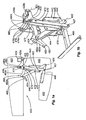
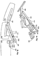
- FIGS. 1 and 1a to 1h show an embodiment of a piece of furniture designed as a piece of upholstered furniture 410 according to the invention, of which only the main segment 420 is shown with top side seat, the leg segment 440 and the end segment 460 and the relative movement of these segments 420, 440, 460 provided mechanism.
- Other components of the piece of furniture are not shown. These components, not shown, comprise a base frame on which the main segment 420 rests in a stationary manner, armrests on both sides of the main segment 420 and a backrest on the end of the main segment 420 facing away from the leg and end segments 440, 460.
- Fig. 1a to 1h illustrated positions include sectional representations 1a, 1c, 1e, 1g of the seat piece of furniture and perspective views 1b, 1d, 1f, 1h of the mechanics.
- the mechanism is largely mirror-inverted. Components that are thereby present in duplicate are each referred to below in the singular, in which case both components are meant.
- the segments of this embodiment 420, 440, 460 are arranged in a chain behind one another, said mechanism being provided for coupling the segments and their movement.
- the mechanism is fixed by screwing to a square hollow profile 428, which is part of a base frame of the seating piece 410.
- a flange block 428a is fixed, to which a connecting member 480 and a positive guide member 482 are pivotally connected about mutually parallel first and second pivot axes 401, 403.
- the connecting member 480 and the positive guide member 482 are also each pivotally mounted to the leg segment 440 about also parallel to each other third and fourth pivot axes 402, 404.
- a fastening element 443 formed by an L-shaped profile 445 and a rod-shaped extension 444 immovably connected thereto is provided on the underside of the leg segment 440.
- This fastener 443 is bolted to a wooden plate 41, which forms the base for the padding of the leg segment 440.
- the second pivot axis 402 is formed by an axle pin which is provided on the L-shaped profile 445.
- the fourth pivot axis 404 is formed by an axle pin disposed at the distal end of the boom 444.
- a roller member 476 is provided which has an inner main roller 476a and an outer minor roller 476b of smaller diameter, which are rotatably mounted on the auxiliary member 470 about a common roller pivot axis 408.
- the axis of rotation 408 is aligned parallel to the auxiliary member pivot axis 407.
- the roller unit 476 abuts both the connecting member 480 and the positive guide member 482.
- a guide track 480b designed as a curved elongated hole is provided in the connecting member 480, which guide groove extends approximately in the extension direction of the connecting member 480.
- the positive guide 482 a first guide track 483 is provided, which comprises a first guide track section 483a and a second guide track section 483b.
- the inner roller 476a of the roller unit 476 is associated with the first guide track 483.
- the outer roller 476b of the reel unit 476 is associated with the second guide track 480b.
- roller unit 476 Through the roller unit 476 and the guide tracks 480b, 483, there is an effective coupling between the members 480, 482 for moving the leg segment 440 and the auxiliary member 470 for moving the end segment 460 and the leg segment 440.
- the described system can be controlled via only the already mentioned single control member 492, which acts on the articulation point 472 of the auxiliary members 470.
- the pivot point 472 is controlled by this control member 492 in the direction of in the FIG. 1a shown arrow 474 force. This is done via the in Fig. 1 shown linear actuator 412.
- This Kraftbeetzung leads starting from the state of Fig. 1a, 1b in that the leg segment 440 and the end segment 460 are transferred from their respective stowed state to their respective functional state, which in the Figures 1g and 1h is shown.
- the leg segment 440 is pivoted downwards by about 90 ° relative to the functional state.
- the end segment 460 is also pivoted about the leg segment 440 by about 90 ° and thus pivoted about 180 ° relative to its functional position.
- the reel unit 476 is arranged in this initial state at the end pointing to the third pivot axis 403 of the guide track portion 483a of the first guide track 483 and is supported on this guide track 483, so that the end segment 460 can not fall further.
- the roller unit 476 is in the initial state of FIGS.
- the shape of the first guide track portion 483a of the guide track 483 ensures that the roller unit 476 until reaching the intermediate state of the FIGS. 1e and 1f remains in said end portion of the second guide tracks 480b. Since the position of the roller unit 476 in the second guide track 480b simultaneously determines the relative position of the end segment 460 to the leg segment 440, this relative position likewise remains largely unchanged. This allows the transition from the starting position of the FIGS. 1a and 1b to the intermediate position of FIGS. 1e and 1f a collision between the end segment 460 and that not shown in the figures Avoid floor. This is further supported by the fact that the leg segment 440 in the transition to its functional position in the meantime at the state of FIGS. 1e, 1f is raised beyond its end position.
- the roller 476a on the first guide track 483 has reached the boundary between the first guide track section 483a and the second guide track section 483b, thus completing a first movement phase dominated in the relative movement between the main segment 420 and the leg segment 440.
- the second movement phase of the movement of the end segment 460 begins. Since the movement limiting effect of the first guide track portion 483a with respect to the relative position of the end segment 460 to the leg segment 440 is no longer present in this second phase, the reel unit 476 may terminate the end portion of the second guide track 480b leave and be moved towards the opposite end. As in the state of FIGS.
- seat piece of furniture allows it by the construction of its mechanics, with only one control member 492 the complete movement from the stowed position of the leg segment 440 and the end segment 460 to perform their functional position.
- Acting as a slider roller unit 476 is used in conjunction with the first function track 483 to move in the first movement phase, the leg segment 440, while a relative movement of the end segment 460 to the leg segment 440 is largely blocked. The end of this blocking is achieved when the reel unit 476 exceeds the boundary area between the guide track portions 483a and 483b, since from this point on, movement of the reel unit 476 in the second guide tracks 480b is no longer limited by the first guide track 483.
Landscapes
- Chairs For Special Purposes, Such As Reclining Chairs (AREA)
- Hinges (AREA)
- Special Chairs (AREA)
- Mattresses And Other Support Structures For Chairs And Beds (AREA)
- Carriages For Children, Sleds, And Other Hand-Operated Vehicles (AREA)
Claims (38)
- Meuble d'assise (410), en particulier meuble d'assise rembourré, avec- un segment principal (420) s'étendant essentiellement à l'horizontale, sur la face supérieure duquel est prévue une surface d'assise, et- un segment pour les jambes (440), sur la face supérieure duquel est prévue une surface d'appui,
sachant que- le segment pour les jambes (440) peut être déplacé par rapport au segment principal (420) entre une position de rangement et une position fonctionnelle, ledit segment étantet que- disposé, dans sa position fonctionnelle, devant un bord avant du segment principal (420) et orienté de telle manière que la surface d'appui s'étend essentiellement à l'horizontale, et- disposé, dans sa position de rangement, au moins en partie sous le segment principal (420) et incliné par rapport à la position fonctionnelle,- le segment pour les jambes (440) est fixé au segment principal (420) au moyen d'un élément de connexion rigide (480), l'élément de connexion (480) étantcaractérisé en ce- articulé sur le segment principal (420) ou sur un châssis de base du meuble d'assise de manière à pivoter autour d'un premier axe de pivotement (401) fixe par rapport au segment principal (420) ou au châssis de base du meuble d'assise, et- articulé sur le segment pour les jambes (440) de manière à pivoter autour d'un deuxième axe de pivotement (402) fixe par rapport au segment pour les jambes (440),- que sont prévus des moyens de guidage forcé (482) grâce auxquels une position relative définie de l'élément de connexion (480) par rapport au segment pour les jambes (440) est associée à chaque position relative de l'élément de connexion (480) par rapport au segment principal (420) ou au châssis de base,- qu'est prévu un segment d'extrémité (460) sur la face supérieure duquel est prévue une surface d'appui, sachant que le segment d'extrémité (460) peut être déplacé par rapport au segment pour les jambes (440) entre une position de rangement et une position fonctionnelle, et qu'il est disposé, dans sa position fonctionnelle, devant le bord avant du segment pour les jambes (440), et- qu'est prévu un système coulissant avec un coulisseau (476),- qui est couplé fonctionnellement au segment d'extrémité (460) par l'intermédiaire d'un élément auxiliaire (470) rigide et- qui est conçu comme une première section de commande (476, 476a) pour fonctionner en interaction avec une première piste de commande (483), dont la position est obligatoirement couplée à la position du segment pour les jambes (440). - Meuble d'assise (410) selon la revendication 1,
caractérisé en ce
que le deuxième axe de pivotement (402) est, en position de rangement, disposé derrière le premier axe de pivotement (401) par rapport à une ligne horizontale. - Meuble d'assise (410) selon la revendication 1 ou 2,
caractérisé en ce
que le segment pour les jambes (440) peut être pivoté d'un angle de 60° à 150°, de préférence de 75° à 120° entre sa position de rangement et sa position fonctionnelle. - Meuble d'assise (410) selon l'une des revendications précédentes,
caractérisé en ce- que le premier axe de pivotement (401) est prévu à l'horizontale dans la zone du bord avant du segment principal (420) et/ou- que le premier axe de pivotement (401) est prévu à la verticale dans la zone de la hauteur de la face inférieure du segment principal (420). - Meuble d'assise (410) selon l'une des revendications précédentes,
caractérisé en ce
que le premier axe de pivotement (401) est défini par un moyen de charnière qui est fixé sur le cadre (428) du segment principal (420) ou du châssis de base du meuble. - Meuble d'assise (410) selon l'une des revendications précédentes,
caractérisé en ce
que l'élément de connexion (480) présente une forme contrecoudée ou courbée. - Meuble d'assise (410) selon l'une des revendications précédentes,
caractérisé en ce
qu'est prévu un moyen de guidage forcé (482), qui- est articulé sur le segment principal (420) ou sur un châssis de base du meuble d'assise de manière à pivoter autour d'un troisième axe de pivotement (403) fixe par rapport au segment principal (420) ou au châssis de base du meuble d'assise, et qui- est articulé sur le segment pour les jambes (440) de manière à pivoter autour d'un quatrième axe de pivotement (404) fixe par rapport au segment pour les jambes (440). - Meuble d'assise (410) selon l'une des revendications précédentes,
caractérisé en ce
que le deuxième et/ou le quatrième axe de pivotement (404) est formé par un moyen de charnière, qui est prévu sur un bras (444) qui, en position fonctionnelle, s'étend vers le bas depuis une face inférieure du segment pour les jambes (440). - Meuble d'assise selon l'une des revendications 7 et 8,
caractérisé en ce- que le troisième axe de pivotement (403) est disposé derrière le premier axe de pivotement (401),- que l'élément de connexion (480) est basculé lors du passage de la position de rangement à la position fonctionnelle d'un angle compris entre 95° et 150°, et- que le moyen de guidage forcé (482) est basculé lors du passage de la position de rangement à la position fonctionnelle d'un angle compris entre 130° et 180°. - Meuble d'assise selon l'une des revendications 7 à 9
caractérisé en ce- que l'écartement entre le troisième axe de pivotement (403) et le quatrième axe de pivotement (404) est supérieur d'un facteur de 1,5 à 1,9 à l'écartement du premier axe de pivotement (401) par rapport au troisième axe de pivotement (403),- que l'écartement entre le premier axe de pivotement (401) et le deuxième axe de pivotement (402) est supérieur d'un facteur de 2,9 à 3,3 à l'écartement du premier axe de pivotement (401) par rapport au troisième axe de pivotement (403), et- que l'écartement entre le deuxième axe de pivotement (402) et le quatrième axe de pivotement (404) est supérieur d'un facteur de 2,4 à 2,8 à l'écartement du premier axe de pivotement (401) par rapport au troisième axe de pivotement (403). - Meuble d'assise selon l'une des revendications 7 à 10,
caractérisé en ce
que les premier, deuxième, troisième et quatrième axes de pivotement (401, 402, 403, 404) sont disposés de telle manière que la direction d'extension de l'élément de connexion (480) et la direction d'extension du moyen de guidage forcé (482) incluent toujours un angle > 15° lors du passage de la position de rangement à la position fonctionnelle du segment pour les jambes (440). - Meuble d'assise selon l'une des revendications précédentes,
caractérisé par
un segment de dossier, lequel peut être pivoté autour d'un axe de dossier par rapport au segment principal, sachant que le segment de dossier est fonctionnellement couplé au segment pour les jambes par l'intermédiaire de moyens de couplage, qu'une position relative du segment pour les jambes par rapport au segment principal ou au châssis de base est associée à chaque position relative du segment de dossier par rapport au segment principal ou au châssis de base. - Meuble d'assise selon l'une des revendications précédentes,
caractérisé en ce
que sont prévus au moins deux membres de commande rigides qui présentent respectivement une première section d'articulation dont la position peut être modifiée au moyen d'un moteur électrique respectif, et qui sont articulés sur le segment pour les jambes avec respectivement une deuxième section d'articulation, et/ou sur un élément de connexion rigide entre le segment principal et le segment pour les jambes, et/ou sur un glissoir mobile en translation. - Meuble d'assise selon l'une des revendications précédentes,
caractérisé en ce- qu'est prévu un organe rotatif qui est conçu de manière à pouvoir tourner autour d'un axe d'organe rotatif fixe par rapport au segment principal ou à un châssis de base du meuble,- qu'est prévu au moins un membre de commande rigide qui est articulé sur l'organe rotatif par une première section d'articulation, et qui est articulé au moyen d'une deuxième section d'articulation sur le segment pour les jambes, et/ou sur un élément de connexion rigide entre le segment principal et le segment pour les jambes, et/ou sur un glissoir mobile en translation, et/ou sur un élément auxiliaire pour le mouvement indirect du segment pour les jambes. - Dispositif selon la revendication 14,
caractérisé en ce
que sont prévus au moins deux membres de commande rigides. - Meuble d'assise selon la revendication 15,
caractérisé en ce
que les deux membres de commande sont articulés sur le segment pour les jambes par leur deuxième section d'articulation respective. - Meuble d'assise selon la revendication 16,
caractérisé en ce- qu'un premier membre de commande est articulé sur l'élément de connexion par sa deuxième section d'articulation, et- qu'un deuxième membre de commande est articulé sur le segment pour les jambes par sa deuxième section d'articulation. - Meuble d'assise selon l'une des revendications 14 à 17,
caractérisé en ce- que l'axe de l'organe rotatif est orienté approximativement de manière verticale. - Meuble d'assise selon l'une des revendications 14 à 18,
caractérisé en ce
que l'organe rotatif est disposé au-dessous de la surface d'assise du segment principal. - Meuble d'assise selon l'une des revendications 14 à 19,
caractérisé en ce
que l'organe rotatif est fonctionnellement couplé à un électromoteur conçu pour la rotation de l'organe rotatif autour de l'axe de l'organe rotatif. - Meuble d'assise selon la revendication 20,
caractérisé en ce
que l'organe rotatif et l'électromoteur sont conçus sous forme de composant commun intégral, sachant que ce composant intégral présente des sections de connexion pour la fixation sur le segment principal et/ou un châssis de base du meuble d'assise. - Meuble d'assise selon l'une des revendications 14 à 21,
caractérisé en ce
que l'organe rotatif est fonctionnellement couplé à une manette pouvant être actionnée manuellement qui est conçue pour la rotation de l'organe rotatif autour de l'axe de l'organe rotatif. - Meuble d'assise selon l'une des revendications 14 à 22,
caractérisé en ce
que l'organe rotatif s'appuie contre une butée limitant au moins indirectement le mouvement de rotation, dans une position de rotation dans laquelle le segment pour les jambes est disposé dans sa position fonctionnelle, et/ou dans une position de rotation dans laquelle le segment pour les jambes est disposé dans sa position de rangement. - Meuble d'assise selon la revendication 23,
caractérisé en ce
que l'organe rotatif et le premier membre de commande et/ou le deuxième membre de commande sont conçus et disposés de telle manière que, dans la position fonctionnelle du segment pour les jambes, une force de pression agissant sur le premier ou le deuxième membre de commande appuie l'organe rotatif par un couple de torsion contre la butée . - Meuble d'assise selon l'une des revendications 14 à 24,
caractérisé par
un segment de dossier, lequel peut être pivoté autour d'un axe de dossier par rapport au segment principal, sachant que le segment de dossier est fonctionnellement couplé avec l'organe rotatif par l'intermédiaire de moyens de couplage de sorte qu'une position de rotation de l'organe rotatif est associée à chaque position relative du segment de dossier par rapport au segment principal ou un châssis de base. - Meuble d'assise (410) selon l'une des revendications précédentes,
caractérisé en ce
que le segment d'extrémité (460) est conçu de manière à pivoter autour d'un axe du segment d'extrémité (406) par rapport au segment pour les jambes (440), sachant que l'axe du segment d'extrémité (406) est fixe par rapport au segment d'extrémité (460) et au segment pour les jambes (440). - Meuble d'assise (410) selon l'une des revendications précédentes,
caractérisé en ce
que le segment d'extrémité (460) est, dans sa position de rangement, pivoté par rapport au segment pour les jambes (440) d'environ un angle de 50° à 130° et/ou est disposé approximativement parallèlement au segment principal (420). - Meuble d'assise (410) selon l'une des revendications précédentes,
caractérisé en ce
que la première piste de commande (483) et le coulisseau (476, 476a) sont adaptés de telle manière l'un à l'autre que, lors du passage du segment pour les jambes (440) et du segment d'extrémité (460) de la position de rangement à la position fonctionnelle,- le segment pour les jambes (440) est, dans une première phase du mouvement, pivoté par rapport au segment principal (420) d'au moins 70° dans le sens de la position fonctionnelle, alors que le segment d'extrémité (460) est pivoté d'au maximum 50° par rapport au segment pour les jambes (440) dans le sens de la position fonctionnelle, et- le segment pour les jambes (440) et le segment d'extrémité (460) atteignent respectivement leur position fonctionnelle dans une seconde phase du mouvement. - Meuble d'assise (410) selon l'une des revendications précédentes,
caractérisé en ce
que la première piste de commande (483) est prévue sur le moyen de guidage forcé (482), sur l'élément de connexion ou sur le segment pour les jambes. - Meuble d'assise (410) selon l'une des revendications précédentes,
caractérisé en ce
que l'élément auxiliaire (470) présente une deuxième section de commande (476, 476b) mobile le long d'une deuxième piste de commande (480b), sachant que la deuxième piste de commande (480b) est prévue de préférence sur l'élément de connexion (480) ou sur le moyen de guidage forcé. - Meuble d'assise selon l'une des revendications précédentes,
caractérisé en ce
que l'élément auxiliaire est articulé sur le segment principal ou un châssis de base du meuble d'assise au moyen d'un élément intermédiaire relié de manière pivotante à l'élément auxiliaire. - Meuble d'assise selon l'une des revendications précédentes,
caractérisé en ce
qu'est prévu sur l'organe rotatif un premier membre de commande rigide de segment d'extrémité qui est articulé sur l'organe rotatif par une première section d'articulation et qui est fonctionnellement couplé au segment d'extrémité de telle sorte qu'un mouvement de l'organe rotatif provoque un mouvement relatif du segment d'extrémité par rapport au segment pour les jambes. - Meuble d'assise selon l'une des revendications 14 à 32,
caractérisé en ce
que les premières sections d'articulation des membres de commande sont au moins en partie- articulées sur l'organe rotatif en diverses positions angulaires par rapport à l'axe de l'organe rotatif et/ou- articulées sur l'organe rotatif à diverses distances par rapport à l'axe de l'organe rotatif. - Meuble d'assise selon l'une des revendications précédentes,
caractérisé en ce
que, dans la position fonctionnelle du segment pour les jambes,- une ligne de liaison entre l'axe de l'organe rotatif et un premier point d'articulation du premier membre de commande inclut avec une direction principale d'extension du premier membre de commande un angle ne dépassant pas 20°,- une ligne de liaison entre l'axe de l'organe rotatif et un premier point d'articulation du deuxième membre de commande inclut avec une direction principale d'extension du deuxième membre de commande un angle ne dépassant pas 20°, et/ou- une ligne de liaison entre l'axe de l'organe rotatif et un premier point d'articulation du premier membre de commande du segment d'extrémité inclut avec une direction principale d'extension du premier membre de commande du segment d'extrémité un angle compris entre 60° et 120°. - Meuble d'assise selon l'une des revendications 32 à 34,
caractérisé en ce
que le premier membre de commande du segment d'extrémité est relié par sa deuxième section d'articulation à un deuxième membre de commande du segment d'extrémité (93; 193; 293; 393), lequel est articulé sur le premier membre de commande du segment d'extrémité (92; 192; 292; 392) par une première section d'articulation et sur le segment d'extrémité (60; 160; 260; 360) par une deuxième section d'articulation. - Meuble d'assise selon l'une des revendications 32 à 35,
caractérisé en ce
qu'est prévu un moyen de guidage qui est fixe par rapport au segment principal ou à un châssis de base ou au segment pour les jambes, ou est conduit par force en fonction de la position relative du segment pour les jambes par rapport au segment principal, sachant que le premier membre de commande du segment d'extrémité est monté sur ce moyen de guidage de manière à pouvoir être déplacé. - Meuble d'assise selon l'une des revendications précédentes,
caractérisé par
un châssis de base, sachant que le segment principal est conçu de manière mobile par rapport au châssis de base. - Ferrure pour un meuble d'assise selon l'une des revendications précédentes, sachant que- la ferrure présente des premiers moyens de fixation pour la fixation sur un segment principal ou un châssis de base d'un meuble d'assise et des seconds moyens de fixation pour la fixation sur un segment pour les jambes d'un meuble d'assise, et que- le second moyen de fixation pour la fixation du segment pour les jambes peut être déplacé par rapport au premier moyen de fixation pour la fixation du segment principal entre une position de rangement et une position fonctionnelle, si bien que le segment pour les jambeset sachant que- est, dans sa position fonctionnelle, disposé devant un bord avant du segment principal et orienté de telle manière que la surface d'appui s'étend essentiellement à l'horizontale, et- est, dans sa position de rangement, disposé au moins en partie sous le segment principal et incliné par rapport à la position fonctionnelle
la ferrure présente un élément de connexion rigide, sachant que l'élément de connexion rigide- est articulé sur la première section de fixation de manière à pivoter autour d'un premier axe de pivotement fixe par rapport à la première section de fixation, et que- est articulé sur la deuxième section de fixation de manière à pivoter autour d'un deuxième axe de pivotement fixe par rapport à la deuxième section de fixation,
caractérisée en ce- que sont prévus des moyens de guidage forcé grâce auxquels une position relative définie de l'élément de connexion par rapport au deuxième moyen de fixation pour la fixation du segment pour les jambes est associée à chaque position relative de l'élément de connexion par rapport au premier moyen de fixation pour la fixation du segment principal ou par rapport au châssis de base,- que la ferrure est conçue pour la mise en place d'un segment d'extrémité, de sorte que le segment d'extrémité peut être déplacé par rapport au moyen de fixation pour la fixation du segment pour les jambes entre une position de rangement et une position fonctionnelle, et de sorte que le segment d'extrémité est disposé, dans sa position fonctionnelle, devant le bord avant du segment pour les jambes, et- qu'est prévu un système coulissant avec un coulisseau,- lequel est fonctionnellement couplé avec le segment d'extrémité par l'intermédiaire d'un élément auxiliaire rigide, et- qui est conçu comme première section de commande pour fonctionner en interaction avec une première piste de commande dont la position est obligatoirement couplée à la position du moyen de fixation pour la fixation du segment pour les jambes.
Priority Applications (8)
| Application Number | Priority Date | Filing Date | Title |
|---|---|---|---|
| BRPI0907768-5A BRPI0907768A2 (pt) | 2008-02-04 | 2009-02-04 | Poltrona e guarnição |
| RU2010135415/12A RU2010135415A (ru) | 2008-02-04 | 2009-02-04 | Предмет мебели для сидения и соединительный элемент для этого предмета мебели |
| AU2009211864A AU2009211864A1 (en) | 2008-02-04 | 2009-02-04 | Piece of furniture for sitting on, and mounting therefor |
| PCT/EP2009/000747 WO2009098040A2 (fr) | 2008-02-04 | 2009-02-04 | Meuble d'assise et ferrure pour celui-ci |
| CN2009801118313A CN101983023A (zh) | 2008-02-04 | 2009-02-04 | 坐具和用于该坐具的配件 |
| JP2010545397A JP2011510769A (ja) | 2008-02-04 | 2009-02-04 | 座家具およびその金具 |
| US12/735,650 US20110043005A1 (en) | 2008-02-04 | 2009-02-04 | Piece of seating furniture and fitting for the same |
| CA2714036A CA2714036A1 (fr) | 2008-02-04 | 2009-02-04 | Meuble d'assise et ferrure pour celui-ci |
Applications Claiming Priority (1)
| Application Number | Priority Date | Filing Date | Title |
|---|---|---|---|
| DE102008009234A DE102008009234A1 (de) | 2008-02-04 | 2008-02-04 | Sitzmöbelstück und Beschlag hierfür |
Publications (3)
| Publication Number | Publication Date |
|---|---|
| EP2084992A2 EP2084992A2 (fr) | 2009-08-05 |
| EP2084992A3 EP2084992A3 (fr) | 2010-04-07 |
| EP2084992B1 true EP2084992B1 (fr) | 2012-11-14 |
Family
ID=40674610
Family Applications (1)
| Application Number | Title | Priority Date | Filing Date |
|---|---|---|---|
| EP08005448A Not-in-force EP2084992B1 (fr) | 2008-02-04 | 2008-03-25 | Siège et sa monture |
Country Status (10)
| Country | Link |
|---|---|
| US (1) | US20110043005A1 (fr) |
| EP (1) | EP2084992B1 (fr) |
| JP (1) | JP2011510769A (fr) |
| CN (1) | CN101983023A (fr) |
| AU (1) | AU2009211864A1 (fr) |
| BR (1) | BRPI0907768A2 (fr) |
| CA (1) | CA2714036A1 (fr) |
| DE (1) | DE102008009234A1 (fr) |
| RU (1) | RU2010135415A (fr) |
| WO (1) | WO2009098040A2 (fr) |
Families Citing this family (26)
| Publication number | Priority date | Publication date | Assignee | Title |
|---|---|---|---|---|
| JP5573382B2 (ja) | 2010-06-08 | 2014-08-20 | トヨタ紡織株式会社 | クッション長可変シートのオットマン装置 |
| WO2012165463A1 (fr) * | 2011-06-03 | 2012-12-06 | 株式会社岡村製作所 | Structure pour attacher un élément facultatif à un socle de siège |
| US8985694B2 (en) | 2011-12-28 | 2015-03-24 | Kintec-Solution Gmbh | Item of seating furniture and fitting therefor |
| DK2609834T3 (da) | 2011-12-28 | 2014-09-15 | Kintec Solution Gmbh | Siddemøbel-enhed og beslagsystem hertil |
| WO2014027774A1 (fr) * | 2012-08-17 | 2014-02-20 | Jang Myung Su | Bac à shampooing présentant un siège |
| GB2506665A (en) * | 2012-10-05 | 2014-04-09 | Careflex Ltd | A leg rest with a moving axis of rotation |
| EP2801293B1 (fr) | 2013-05-10 | 2015-12-30 | Kintec Solution GmbH | Elément de siège et sa garniture |
| GB2515545B (en) * | 2013-06-27 | 2016-01-13 | Wan Yu Li | A chair having a foldable leg rest |
| US10604923B2 (en) * | 2014-02-17 | 2020-03-31 | Coway Co., Ltd. | Nozzle assembly and bidet device including same |
| CN104323617B (zh) * | 2014-06-30 | 2017-11-17 | 敏华家具制造(惠州)有限公司 | 沙发 |
| GB201712186D0 (en) * | 2017-07-28 | 2017-09-13 | Motus Mech Ltd | Adjustable furniture |
| US12575682B2 (en) | 2015-03-11 | 2026-03-17 | Motus Mechanics Ltd. | Adjustable furniture |
| EP3192398B1 (fr) * | 2016-01-15 | 2019-12-11 | himolla Polstermöbel GmbH | Couchette/siège |
| US10638847B2 (en) | 2016-03-11 | 2020-05-05 | Innotec Motion GmbH | Footrest chassis for attachment to a seating furniture chassis |
| DE102016106477A1 (de) * | 2016-04-08 | 2017-10-12 | himolla Polstermöbel GmbH | Sitz-/liegemöbel |
| PL3284370T3 (pl) | 2016-08-16 | 2019-09-30 | Beheermaatschappij Vermeulen Beesd B.V. | Okucie do mebla do siedzenia i mebel do siedzenia z takim okuciem |
| CN114052432B (zh) * | 2020-07-30 | 2025-04-11 | 顾家家居股份有限公司 | 一种腿部支撑机构及设有该机构的沙发伸展装置 |
| US11832726B2 (en) * | 2021-05-26 | 2023-12-05 | Ultra-Mek, Inc. | Seating unit with extendable footrest |
| DE102022120164A1 (de) * | 2022-06-13 | 2023-12-14 | Adient Us Llc | Unterschenkelstützvorrichtung für einen fahrzeugsitz sowie fahrzeugsitz |
| CN116035378B (zh) * | 2022-09-16 | 2026-05-12 | 锐迈科技股份有限公司 | 一种腿部居中式支架结构及座椅支架 |
| PL4374741T3 (pl) * | 2022-11-24 | 2026-05-04 | Vermeulen Beheer En Management B.V. | Mebel do siedzenia |
| EP4445798A1 (fr) | 2023-04-14 | 2024-10-16 | Vel Vega - Design e Tecnologia Ind. Unip. Lda. | Meuble d'assise et ferrure de meuble associée |
| DE102023002486A1 (de) | 2023-06-20 | 2024-12-24 | Mercedes-Benz Group AG | Sitzkissentiefeneinstellung in Verbindung mit einer Wadenstütze |
| DE102023119835A1 (de) * | 2023-07-26 | 2025-01-30 | Bayerische Motoren Werke Aktiengesellschaft | Beinauflagesystem für einen Fahrzeugsitz |
| JP7808647B1 (ja) * | 2024-08-13 | 2026-01-29 | 徹 春井 | 座部の形状が変形する作業用椅子 |
| CN121341033B (zh) * | 2025-12-18 | 2026-03-27 | 深圳斯诺凡科技有限公司 | 一种四向气动腿托机构及控制方法、座椅 |
Citations (2)
| Publication number | Priority date | Publication date | Assignee | Title |
|---|---|---|---|---|
| DE3718645C2 (de) * | 1986-08-22 | 1996-07-11 | Appeltshauser Georg Dipl Ing F | Sitzmöbel |
| DE20104534U1 (de) * | 2001-03-16 | 2001-05-31 | Elastoform Polstermöbelwerke Gebr. Brinkel GmbH & Co KG, 47228 Duisburg | Sitzmöbel mit verstellbarer Beinauflage |
Family Cites Families (3)
| Publication number | Priority date | Publication date | Assignee | Title |
|---|---|---|---|---|
| NO903182D0 (no) * | 1990-07-17 | 1990-07-17 | Mobilitet As | Anordning ved fotskammel. |
| DE29501078U1 (de) * | 1995-01-13 | 1995-04-13 | Frank, Wolfgang, 71540 Murrhardt | Sitzmöbel mit in Gebrauchsstellung bringbarem Fußteil |
| DE102005001877A1 (de) * | 2005-01-14 | 2006-07-27 | Deon Ag | Möbel, insbesondere Sitzmöbel |
-
2008
- 2008-02-04 DE DE102008009234A patent/DE102008009234A1/de not_active Withdrawn
- 2008-03-25 EP EP08005448A patent/EP2084992B1/fr not_active Not-in-force
-
2009
- 2009-02-04 WO PCT/EP2009/000747 patent/WO2009098040A2/fr not_active Ceased
- 2009-02-04 CA CA2714036A patent/CA2714036A1/fr not_active Abandoned
- 2009-02-04 CN CN2009801118313A patent/CN101983023A/zh active Pending
- 2009-02-04 RU RU2010135415/12A patent/RU2010135415A/ru not_active Application Discontinuation
- 2009-02-04 BR BRPI0907768-5A patent/BRPI0907768A2/pt not_active IP Right Cessation
- 2009-02-04 JP JP2010545397A patent/JP2011510769A/ja active Pending
- 2009-02-04 AU AU2009211864A patent/AU2009211864A1/en not_active Abandoned
- 2009-02-04 US US12/735,650 patent/US20110043005A1/en not_active Abandoned
Patent Citations (2)
| Publication number | Priority date | Publication date | Assignee | Title |
|---|---|---|---|---|
| DE3718645C2 (de) * | 1986-08-22 | 1996-07-11 | Appeltshauser Georg Dipl Ing F | Sitzmöbel |
| DE20104534U1 (de) * | 2001-03-16 | 2001-05-31 | Elastoform Polstermöbelwerke Gebr. Brinkel GmbH & Co KG, 47228 Duisburg | Sitzmöbel mit verstellbarer Beinauflage |
Also Published As
| Publication number | Publication date |
|---|---|
| WO2009098040A2 (fr) | 2009-08-13 |
| BRPI0907768A2 (pt) | 2015-07-14 |
| RU2010135415A (ru) | 2012-03-20 |
| DE102008009234A1 (de) | 2009-08-06 |
| CA2714036A1 (fr) | 2009-08-13 |
| JP2011510769A (ja) | 2011-04-07 |
| CN101983023A (zh) | 2011-03-02 |
| AU2009211864A1 (en) | 2009-08-13 |
| EP2084992A2 (fr) | 2009-08-05 |
| EP2084992A3 (fr) | 2010-04-07 |
| US20110043005A1 (en) | 2011-02-24 |
| WO2009098040A3 (fr) | 2010-05-27 |
Similar Documents
| Publication | Publication Date | Title |
|---|---|---|
| EP2084992A2 (fr) | Elément de siège et sa garniture | |
| DE2459908C3 (de) | Ausziehvorrichtung für eine Fußstütze bei einem Lehnsessel | |
| EP2609834B1 (fr) | Elément de siège et système d'armature associé | |
| EP3965617B1 (fr) | Siège comprenant une fonction wallaway à double moteur | |
| EP2801293B1 (fr) | Elément de siège et sa garniture | |
| DE102018101721A1 (de) | Sitzmöbel mit höhenverstellbarem Kopfteil | |
| EP1911371A1 (fr) | Meuble d'assise, en particulier chaise de bureau | |
| DE10215028A1 (de) | Sitz, insbesondere Fluggastsitz | |
| EP2777433A1 (fr) | Elément de siège et système d'armature associé | |
| EP3500136B1 (fr) | Armature pour un element de siege et element de siege comprenant une telle armature | |
| EP2741634B1 (fr) | Meuble | |
| EP2053941B1 (fr) | Chaise longue/fauteuil convertible | |
| EP3528664B1 (fr) | Dispositif de mécanisme synchrone et chaise en étant équipée | |
| DE102005051236B4 (de) | Sessel | |
| DE202005000574U1 (de) | Sessel | |
| DE102005001877A1 (de) | Möbel, insbesondere Sitzmöbel | |
| DE202016104973U1 (de) | Gelenkhebelsystem für eine ausschwenkbare Fußstütze eines Sitzmöbels | |
| EP2544568B1 (fr) | Meuble et ferrure pour un meuble | |
| EP1754426B1 (fr) | Siège avec repose-jambes extractable | |
| EP4374741B1 (fr) | Meuble d'assise | |
| DE20204147U1 (de) | Sitzmöbel | |
| DE102017120865A1 (de) | Sitzmöbel mit ausschwenkbarer Fusstütze | |
| DE102023000651A1 (de) | Beinauflagebeschlag für ein Sitz-/Liegemöbel oder einen entsprechenden Funktionsablauf | |
| EP4544962A1 (fr) | Meuble d'assise | |
| EP4585104A1 (fr) | Meuble d'assise |
Legal Events
| Date | Code | Title | Description |
|---|---|---|---|
| PUAI | Public reference made under article 153(3) epc to a published international application that has entered the european phase |
Free format text: ORIGINAL CODE: 0009012 |
|
| AK | Designated contracting states |
Kind code of ref document: A2 Designated state(s): AT BE BG CH CY CZ DE DK EE ES FI FR GB GR HR HU IE IS IT LI LT LU LV MC MT NL NO PL PT RO SE SI SK TR |
|
| AX | Request for extension of the european patent |
Extension state: AL BA MK RS |
|
| RIC1 | Information provided on ipc code assigned before grant |
Ipc: A47C 1/034 20060101ALI20091126BHEP Ipc: A47C 7/50 20060101AFI20091126BHEP |
|
| PUAL | Search report despatched |
Free format text: ORIGINAL CODE: 0009013 |
|
| AK | Designated contracting states |
Kind code of ref document: A3 Designated state(s): AT BE BG CH CY CZ DE DK EE ES FI FR GB GR HR HU IE IS IT LI LT LU LV MC MT NL NO PL PT RO SE SI SK TR |
|
| AX | Request for extension of the european patent |
Extension state: AL BA MK RS |
|
| 17P | Request for examination filed |
Effective date: 20100921 |
|
| 17Q | First examination report despatched |
Effective date: 20101019 |
|
| RAP1 | Party data changed (applicant data changed or rights of an application transferred) |
Owner name: KINTEC SOLUTION GMBH |
|
| AKX | Designation fees paid |
Designated state(s): AT BE BG CH CY CZ DE DK EE ES FI FR GB GR HR HU IE IS IT LI LT LU LV MC MT NL NO PL PT RO SE SI SK TR |
|
| GRAP | Despatch of communication of intention to grant a patent |
Free format text: ORIGINAL CODE: EPIDOSNIGR1 |
|
| RTI1 | Title (correction) |
Free format text: SEATING FURNITURE AND MOUNTING FOR SAME |
|
| GRAS | Grant fee paid |
Free format text: ORIGINAL CODE: EPIDOSNIGR3 |
|
| GRAP | Despatch of communication of intention to grant a patent |
Free format text: ORIGINAL CODE: EPIDOSNIGR1 |
|
| RIN1 | Information on inventor provided before grant (corrected) |
Inventor name: FISCHER, MATTHIAS, DIPL.-DES. |
|
| GRAA | (expected) grant |
Free format text: ORIGINAL CODE: 0009210 |
|
| AK | Designated contracting states |
Kind code of ref document: B1 Designated state(s): AT BE BG CH CY CZ DE DK EE ES FI FR GB GR HR HU IE IS IT LI LT LU LV MC MT NL NO PL PT RO SE SI SK TR |
|
| REG | Reference to a national code |
Ref country code: GB Ref legal event code: FG4D Free format text: NOT ENGLISH |
|
| REG | Reference to a national code |
Ref country code: CH Ref legal event code: EP Ref country code: AT Ref legal event code: REF Ref document number: 583498 Country of ref document: AT Kind code of ref document: T Effective date: 20121115 |
|
| REG | Reference to a national code |
Ref country code: IE Ref legal event code: FG4D Free format text: LANGUAGE OF EP DOCUMENT: GERMAN |
|
| REG | Reference to a national code |
Ref country code: DE Ref legal event code: R096 Ref document number: 502008008622 Country of ref document: DE Effective date: 20130110 |
|
| REG | Reference to a national code |
Ref country code: NL Ref legal event code: VDEP Effective date: 20121114 |
|
| REG | Reference to a national code |
Ref country code: LT Ref legal event code: MG4D |
|
| PG25 | Lapsed in a contracting state [announced via postgrant information from national office to epo] |
Ref country code: SE Free format text: LAPSE BECAUSE OF FAILURE TO SUBMIT A TRANSLATION OF THE DESCRIPTION OR TO PAY THE FEE WITHIN THE PRESCRIBED TIME-LIMIT Effective date: 20121114 Ref country code: NO Free format text: LAPSE BECAUSE OF FAILURE TO SUBMIT A TRANSLATION OF THE DESCRIPTION OR TO PAY THE FEE WITHIN THE PRESCRIBED TIME-LIMIT Effective date: 20130214 Ref country code: ES Free format text: LAPSE BECAUSE OF FAILURE TO SUBMIT A TRANSLATION OF THE DESCRIPTION OR TO PAY THE FEE WITHIN THE PRESCRIBED TIME-LIMIT Effective date: 20130225 Ref country code: LT Free format text: LAPSE BECAUSE OF FAILURE TO SUBMIT A TRANSLATION OF THE DESCRIPTION OR TO PAY THE FEE WITHIN THE PRESCRIBED TIME-LIMIT Effective date: 20121114 Ref country code: FI Free format text: LAPSE BECAUSE OF FAILURE TO SUBMIT A TRANSLATION OF THE DESCRIPTION OR TO PAY THE FEE WITHIN THE PRESCRIBED TIME-LIMIT Effective date: 20121114 Ref country code: HR Free format text: LAPSE BECAUSE OF FAILURE TO SUBMIT A TRANSLATION OF THE DESCRIPTION OR TO PAY THE FEE WITHIN THE PRESCRIBED TIME-LIMIT Effective date: 20121114 |
|
| PG25 | Lapsed in a contracting state [announced via postgrant information from national office to epo] |
Ref country code: CY Free format text: LAPSE BECAUSE OF FAILURE TO SUBMIT A TRANSLATION OF THE DESCRIPTION OR TO PAY THE FEE WITHIN THE PRESCRIBED TIME-LIMIT Effective date: 20121114 Ref country code: PT Free format text: LAPSE BECAUSE OF FAILURE TO SUBMIT A TRANSLATION OF THE DESCRIPTION OR TO PAY THE FEE WITHIN THE PRESCRIBED TIME-LIMIT Effective date: 20130314 Ref country code: GR Free format text: LAPSE BECAUSE OF FAILURE TO SUBMIT A TRANSLATION OF THE DESCRIPTION OR TO PAY THE FEE WITHIN THE PRESCRIBED TIME-LIMIT Effective date: 20130215 Ref country code: SI Free format text: LAPSE BECAUSE OF FAILURE TO SUBMIT A TRANSLATION OF THE DESCRIPTION OR TO PAY THE FEE WITHIN THE PRESCRIBED TIME-LIMIT Effective date: 20121114 Ref country code: PL Free format text: LAPSE BECAUSE OF FAILURE TO SUBMIT A TRANSLATION OF THE DESCRIPTION OR TO PAY THE FEE WITHIN THE PRESCRIBED TIME-LIMIT Effective date: 20121114 Ref country code: LV Free format text: LAPSE BECAUSE OF FAILURE TO SUBMIT A TRANSLATION OF THE DESCRIPTION OR TO PAY THE FEE WITHIN THE PRESCRIBED TIME-LIMIT Effective date: 20121114 |
|
| PG25 | Lapsed in a contracting state [announced via postgrant information from national office to epo] |
Ref country code: BG Free format text: LAPSE BECAUSE OF FAILURE TO SUBMIT A TRANSLATION OF THE DESCRIPTION OR TO PAY THE FEE WITHIN THE PRESCRIBED TIME-LIMIT Effective date: 20130214 Ref country code: SK Free format text: LAPSE BECAUSE OF FAILURE TO SUBMIT A TRANSLATION OF THE DESCRIPTION OR TO PAY THE FEE WITHIN THE PRESCRIBED TIME-LIMIT Effective date: 20121114 Ref country code: EE Free format text: LAPSE BECAUSE OF FAILURE TO SUBMIT A TRANSLATION OF THE DESCRIPTION OR TO PAY THE FEE WITHIN THE PRESCRIBED TIME-LIMIT Effective date: 20121114 Ref country code: CZ Free format text: LAPSE BECAUSE OF FAILURE TO SUBMIT A TRANSLATION OF THE DESCRIPTION OR TO PAY THE FEE WITHIN THE PRESCRIBED TIME-LIMIT Effective date: 20121114 Ref country code: DK Free format text: LAPSE BECAUSE OF FAILURE TO SUBMIT A TRANSLATION OF THE DESCRIPTION OR TO PAY THE FEE WITHIN THE PRESCRIBED TIME-LIMIT Effective date: 20121114 |
|
| PG25 | Lapsed in a contracting state [announced via postgrant information from national office to epo] |
Ref country code: IT Free format text: LAPSE BECAUSE OF FAILURE TO SUBMIT A TRANSLATION OF THE DESCRIPTION OR TO PAY THE FEE WITHIN THE PRESCRIBED TIME-LIMIT Effective date: 20121114 Ref country code: RO Free format text: LAPSE BECAUSE OF FAILURE TO SUBMIT A TRANSLATION OF THE DESCRIPTION OR TO PAY THE FEE WITHIN THE PRESCRIBED TIME-LIMIT Effective date: 20121114 Ref country code: NL Free format text: LAPSE BECAUSE OF FAILURE TO SUBMIT A TRANSLATION OF THE DESCRIPTION OR TO PAY THE FEE WITHIN THE PRESCRIBED TIME-LIMIT Effective date: 20121114 |
|
| PLBE | No opposition filed within time limit |
Free format text: ORIGINAL CODE: 0009261 |
|
| STAA | Information on the status of an ep patent application or granted ep patent |
Free format text: STATUS: NO OPPOSITION FILED WITHIN TIME LIMIT |
|
| BERE | Be: lapsed |
Owner name: KINTEC-SOLUTION G.M.B.H. Effective date: 20130331 |
|
| 26N | No opposition filed |
Effective date: 20130815 |
|
| PG25 | Lapsed in a contracting state [announced via postgrant information from national office to epo] |
Ref country code: MC Free format text: LAPSE BECAUSE OF NON-PAYMENT OF DUE FEES Effective date: 20130331 |
|
| REG | Reference to a national code |
Ref country code: CH Ref legal event code: PL |
|
| REG | Reference to a national code |
Ref country code: DE Ref legal event code: R097 Ref document number: 502008008622 Country of ref document: DE Effective date: 20130815 |
|
| REG | Reference to a national code |
Ref country code: IE Ref legal event code: MM4A |
|
| PG25 | Lapsed in a contracting state [announced via postgrant information from national office to epo] |
Ref country code: LI Free format text: LAPSE BECAUSE OF NON-PAYMENT OF DUE FEES Effective date: 20130331 Ref country code: IE Free format text: LAPSE BECAUSE OF NON-PAYMENT OF DUE FEES Effective date: 20130325 Ref country code: BE Free format text: LAPSE BECAUSE OF NON-PAYMENT OF DUE FEES Effective date: 20130331 Ref country code: CH Free format text: LAPSE BECAUSE OF NON-PAYMENT OF DUE FEES Effective date: 20130331 |
|
| REG | Reference to a national code |
Ref country code: AT Ref legal event code: MM01 Ref document number: 583498 Country of ref document: AT Kind code of ref document: T Effective date: 20130325 |
|
| PG25 | Lapsed in a contracting state [announced via postgrant information from national office to epo] |
Ref country code: MT Free format text: LAPSE BECAUSE OF FAILURE TO SUBMIT A TRANSLATION OF THE DESCRIPTION OR TO PAY THE FEE WITHIN THE PRESCRIBED TIME-LIMIT Effective date: 20121114 |
|
| PG25 | Lapsed in a contracting state [announced via postgrant information from national office to epo] |
Ref country code: AT Free format text: LAPSE BECAUSE OF NON-PAYMENT OF DUE FEES Effective date: 20130325 |
|
| PG25 | Lapsed in a contracting state [announced via postgrant information from national office to epo] |
Ref country code: TR Free format text: LAPSE BECAUSE OF FAILURE TO SUBMIT A TRANSLATION OF THE DESCRIPTION OR TO PAY THE FEE WITHIN THE PRESCRIBED TIME-LIMIT Effective date: 20121114 |
|
| PG25 | Lapsed in a contracting state [announced via postgrant information from national office to epo] |
Ref country code: LU Free format text: LAPSE BECAUSE OF NON-PAYMENT OF DUE FEES Effective date: 20130325 Ref country code: HU Free format text: LAPSE BECAUSE OF FAILURE TO SUBMIT A TRANSLATION OF THE DESCRIPTION OR TO PAY THE FEE WITHIN THE PRESCRIBED TIME-LIMIT; INVALID AB INITIO Effective date: 20080325 |
|
| REG | Reference to a national code |
Ref country code: DE Ref legal event code: R082 Ref document number: 502008008622 Country of ref document: DE Representative=s name: PATENTANWALTSKANZLEI CARTAGENA PARTNERSCHAFTSG, DE Ref country code: DE Ref legal event code: R082 Ref document number: 502008008622 Country of ref document: DE Representative=s name: KRAUS & WEISERT PATENTANWAELTE PARTGMBB, DE |
|
| REG | Reference to a national code |
Ref country code: FR Ref legal event code: PLFP Year of fee payment: 9 |
|
| PG25 | Lapsed in a contracting state [announced via postgrant information from national office to epo] |
Ref country code: IS Free format text: LAPSE BECAUSE OF FAILURE TO SUBMIT A TRANSLATION OF THE DESCRIPTION OR TO PAY THE FEE WITHIN THE PRESCRIBED TIME-LIMIT Effective date: 20121114 |
|
| REG | Reference to a national code |
Ref country code: FR Ref legal event code: PLFP Year of fee payment: 10 |
|
| REG | Reference to a national code |
Ref country code: DE Ref legal event code: R082 Ref document number: 502008008622 Country of ref document: DE Representative=s name: KRAUS & WEISERT PATENTANWAELTE PARTGMBB, DE |
|
| REG | Reference to a national code |
Ref country code: FR Ref legal event code: PLFP Year of fee payment: 11 |
|
| PGFP | Annual fee paid to national office [announced via postgrant information from national office to epo] |
Ref country code: GB Payment date: 20200318 Year of fee payment: 13 Ref country code: DE Payment date: 20200310 Year of fee payment: 13 |
|
| PGFP | Annual fee paid to national office [announced via postgrant information from national office to epo] |
Ref country code: FR Payment date: 20200214 Year of fee payment: 13 |
|
| REG | Reference to a national code |
Ref country code: DE Ref legal event code: R119 Ref document number: 502008008622 Country of ref document: DE |
|
| GBPC | Gb: european patent ceased through non-payment of renewal fee |
Effective date: 20210325 |
|
| PG25 | Lapsed in a contracting state [announced via postgrant information from national office to epo] |
Ref country code: DE Free format text: LAPSE BECAUSE OF NON-PAYMENT OF DUE FEES Effective date: 20211001 Ref country code: FR Free format text: LAPSE BECAUSE OF NON-PAYMENT OF DUE FEES Effective date: 20210331 Ref country code: GB Free format text: LAPSE BECAUSE OF NON-PAYMENT OF DUE FEES Effective date: 20210325 |