EP4552982A1 - Dispositif de fixation amovible de charge utile à un support et support pour fixer de manière amovible une charge utile - Google Patents
Dispositif de fixation amovible de charge utile à un support et support pour fixer de manière amovible une charge utile Download PDFInfo
- Publication number
- EP4552982A1 EP4552982A1 EP23208989.6A EP23208989A EP4552982A1 EP 4552982 A1 EP4552982 A1 EP 4552982A1 EP 23208989 A EP23208989 A EP 23208989A EP 4552982 A1 EP4552982 A1 EP 4552982A1
- Authority
- EP
- European Patent Office
- Prior art keywords
- locking
- mounting base
- locking bolt
- coupling ring
- carrier
- Prior art date
- Legal status (The legal status is an assumption and is not a legal conclusion. Google has not performed a legal analysis and makes no representation as to the accuracy of the status listed.)
- Pending
Links
Images


Classifications
-
- B—PERFORMING OPERATIONS; TRANSPORTING
- B64—AIRCRAFT; AVIATION; COSMONAUTICS
- B64G—COSMONAUTICS; VEHICLES OR EQUIPMENT THEREFOR
- B64G1/00—Cosmonautic vehicles
- B64G1/22—Parts of, or equipment specially adapted for fitting in or to, cosmonautic vehicles
- B64G1/64—Systems for coupling or separating cosmonautic vehicles or parts thereof, e.g. docking arrangements
- B64G1/645—Separators
-
- B—PERFORMING OPERATIONS; TRANSPORTING
- B64—AIRCRAFT; AVIATION; COSMONAUTICS
- B64G—COSMONAUTICS; VEHICLES OR EQUIPMENT THEREFOR
- B64G1/00—Cosmonautic vehicles
- B64G1/22—Parts of, or equipment specially adapted for fitting in or to, cosmonautic vehicles
- B64G1/64—Systems for coupling or separating cosmonautic vehicles or parts thereof, e.g. docking arrangements
- B64G1/641—Interstage or payload connectors
Definitions
- the invention relates to a device for releasably fastening payload to a carrier and to a carrier for releasably fastening payload.
- Such devices and carriers are used in spaceflight to transport payloads, such as satellites, into a specific orbit, and then detach and release them there.
- the payload can be coupled to the carrier by several such devices.
- a release mechanism is actuated, causing the devices to release the payload.
- the device according to the invention serves for the releasable fastening of payload to a carrier and comprises a locking unit having a locking mechanism movable between a locking position and a release position, and a mounting base with a locking bolt provided at least in sections with parallel grooves, wherein the locking mechanism has a plurality of pivoting bolts which, in the locking position, lock the locking bolt in the region of the grooves.
- the device according to the invention comprises Device a trigger element that can only be moved translationally and is coupled to the swivel bolts.
- the locking unit can be permanently coupled to the carrier, while the mounting base is permanently mounted to the payload.
- the locking mechanism When the locking mechanism is in the locked position and the pivoting bolts lock the locking pin in the grooves, the payload is thus coupled to the carrier.
- the locking mechanism When triggered by the trigger element coupled to the pivoting bolts, the locking mechanism moves to the release position, where the pivoting bolts release the locking pin, thus decoupled from the locking unit and the mounting base, and thus the carrier and the payload.
- the grooves can, for example, extend circumferentially around a central axis of the locking bolt, so that a plane of extension of the respective grooves is oriented perpendicular to the central axis of the locking bolt.
- the grooves each have a recess adjacent to two ribs extending circumferentially, in particular parallel to the recess.
- the pivot bolts can have a section with a corresponding structure, i.e., in particular, they can also be provided with ribs and adjacent grooves, so that the corresponding structures of the pivot bolts and the locking bolt can engage with each other in the locking position, whereby the locking bolt is locked by the locking mechanism.
- the ribs of the pivot bolts engage with the grooves of the locking bolt, and vice versa.
- the trigger element can be coupled to the swivel bolts via a coupling ring that can only be moved in translation, whereby the directions of movement of the trigger element and the coupling ring can be orthogonal to each other.
- the translational movement of the coupling ring can be converted into a pivoting movement of the swivel bolts via the coupling with the swivel bolts in either The locking position or the release position can be implemented.
- the movement of the trigger element is converted into an orthogonal movement of the coupling ring, so that a translational movement of the trigger element results in a pivoting movement of the swivel bolt.
- the coupling ring is designed as a ring-shaped body, which can be closed in particular in its circumferential direction.
- the coupling ring can be approximately polygonal, rounded, or even circular on its inner and/or outer circumference.
- the coupling ring can also be arranged in a ring receptacle of the locking unit, the inner circumferential surface of which can be designed to be at least partially complementary to the outer circumferential surface of the coupling ring, so that the ring receptacle forms a guide for the translational movement of the coupling ring and prevents tilting or rotational movements of the coupling ring.
- the coupling ring can be connected to each swivel bolt via a pivot lever hinged at both ends, so that the translational movement of the coupling ring causes a pivoting movement of the pivot lever, moving the locking mechanism between the locked and released positions.
- the pivot lever can be designed as a rigid body, and the articulation at both ends can be achieved via pivot joints.
- a central axis of the pivot levers can be oriented orthogonally to the central axis of the locking bolt in the locked position. This causes the respective pivot lever to clamp the respective pivot bolt against the locking bolt, and an initial opening movement of the pivot bolts would run orthogonally to the central axis of the pivot levers, so that the pivot levers serve as toggle levers that block any opening movement of the pivot bolts as long as the coupling ring does not move. As a result, the pivot levers reliably hold the pivot bolts in the locked position.
- the coupling ring can be provided with engagement elements that engage in a slotted guide of the trigger element in order to cause a movement of the coupling ring orthogonal to the trigger element when the trigger element moves.
- the engagement elements can be approximately cylindrical and fastened to the coupling ring.
- the slotted guide can be formed, for example, by slot-like grooves on an inner circumferential surface of the trigger element, into which the engagement elements each protrude.
- the slotted guide can be at least partially oriented in a direction that has a component in the direction of the translational movement of the trigger element and a component in the direction of the translational movement of the coupling ring, i.e., the slotted guide can extend obliquely to the displacement direction of the trigger element.
- the coupling ring can be preloaded in the locked position toward the release position to apply an opening impulse to the coupling ring in the event of a triggering action and to overcome any frictional forces that may occur.
- the coupling ring can be provided with spring elements, particularly compression springs, which are tensioned in the locked position and support the coupling ring against a housing of the locking unit or against a bolt attached to the housing or screwed to the housing.
- the locking mechanism has a guide rail formed by at least one guide rail.
- the locking bolt can be movably connected to the mounting base.
- the locking bolt can rest with its head on the mounting base and protrude with its shaft through a hole in the mounting base, but without being fixed to the mounting base in a translational or rotational manner.
- the mounting base can have a preloading mechanism with which the locking bolt can be preloaded in the locking position relative to the mounting base. This allows a firm and, in particular, play-free Connection between mounting base and locking unit, and thus between payload and carrier, must be established.
- the pretensioning mechanism can have a wedge arrangement, which in particular comprises two wedges, one of which is movable transversely to the central axis of the locking bolt and the other exclusively parallel to the central axis of the locking bolt.
- the wedge movable transversely to the central axis can be adjustable in its position transversely to the central axis, for example by means of an adjusting screw.
- the wedge can slide under the wedge movable exclusively parallel to the central axis of the locking bolt, which is thereby moved parallel to the central axis and pretensions the locking bolt, for example by engaging the head of the locking bolt and thereby exerting a force on the locking bolt in a direction away from the locking unit.
- the wedge In order to define the mobility of the wedge, which is movable exclusively parallel to the central axis of the locking bolt, the wedge can be held in its position by a pin fastened to the mounting base and penetrating the wedge and/or its shape can be adapted to a corresponding recess in the mounting base, so that the wedge is arranged at least partially in a form-fitting manner in the recess.
- the mounting base and the locking unit can have complementary and, in particular, conical centering surfaces, wherein a separating layer can be provided between the centering surfaces. It is also possible for the conical shape of the centering surfaces or of one of the two centering surfaces to be formed by the separating layer itself.
- the separating layer can be positively connected to the locking unit or the mounting base.
- the separating layer can be designed as a conical ring that can be pressed over an overhanging edge of the locking unit or the mounting base.
- the separating layer can be firmly bonded, for example by adhesive bonding, to the centering surface of the mounting base. and/or the centering surface of the locking unit.
- the centering surfaces enable defined and play-free centering of the mounting base and the locking unit relative to each other. Furthermore, the separating layer can prevent unwanted material friction between the mounting base and the locking unit, even leading to friction welding effects, which would complicate or even prevent the release of the mounting base with the payload. Suitable materials for the separating layer include thermoplastics.
- the locking bolt In the release position, the locking bolt can be axially movable in the mounting base against the force of a spring.
- the spring can be used to prevent any undefined and unwanted movements of the locking bolt in the release position, especially after the mounting base and locking unit have been separated.
- the trigger element can be designed as a frame guided by the locking unit. Furthermore, the trigger element can be preloaded against the locking unit by appropriate springs, such as compression springs, in the direction of the release position.
- the carrier according to the invention serves for the releasable attachment of payloads and comprises several devices according to the invention of the type described above, whose locking units are mounted on the carrier, and a rotatably mounted synchronizer ring that is mechanically connected to all trigger elements to simultaneously displace them and thereby move the locking mechanism of all devices from the locked position to the release position.
- a rotatably mounted synchronizer ring that is mechanically connected to all trigger elements to simultaneously displace them and thereby move the locking mechanism of all devices from the locked position to the release position.
- the release elements can be coupled to the synchronizer ring with a certain amount of play.
- the release elements can have a slotted hole for a release pin connected to the synchronizer ring. If release occurs via the synchronizer ring, an impulse is initially generated during an idle stroke (movement within the elongated hole) before the release pin strikes the release element, thereby displacing the release element. This can, in particular, prevent potential friction-related disruptions to the release process by overcoming such friction due to the previously generated impulse.
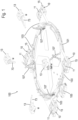
- Fig. 1 shows a carrier 100 for releasably attaching payload, such as a satellite, wherein devices 10 for releasably attaching the payload to the carrier 100 are mounted on the carrier 100.
- devices 10 for releasably attaching the payload to the carrier 100 are mounted on the carrier 100.
- four devices 10 are present.
- the devices 10 each have a locking unit 11, a mounting base 13, each shown in an exploded view removed from the locking unit 11, and a trigger element 15.
- the locking units 11 are each fixedly mounted on the carrier 100, whereas the mounting bases 13 can be fixedly connected to a payload (not shown), such as a satellite.
- the carrier 100 has a synchronizer ring 101, which is preloaded and rotatably mounted and mechanically connected to the trigger elements 15 of the devices 10 via trigger rods 103, so that a rotation of the synchronizer ring 101 causes a simultaneous displacement of all trigger elements 15.
- the rotation of the synchronizer ring 101 is initiated by controlling a trigger unit 105.
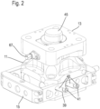
- Fig. 2 to 6 show an example of one of the devices 10 in several views.
- the mounting base 13 and the locking unit 11 are centered relative to each other via a conical centering 55, wherein a separating layer 57 can be provided between the two components, which prevents friction welding effects between the mounting base 13 and the locking unit 11.
- the separating layer 57 is positively and firmly connected to the locking unit 11 and forms the conical centering surface of the locking unit 11.
- the positive connection is achieved by the separating layer 57 being designed as a conical ring that is pressed over an overhanging edge of the locking unit 11.
- a material connection is conceivable, for example by gluing the separating layer 57 to the locking unit 11.
- the mounting base 13 comprises a locking bolt 17 having a head 19, a locking portion 21, and a support portion 23.
- the locking bolt 17 rests with its head 19 on a preloading mechanism having a wedge arrangement 63, 65 and is preloaded against the wedge arrangement 63, 65 by a compression spring 43, which rests at its other spring end against a closure cap 45 firmly attached to the mounting base 13.
- the compression spring 43 serves to prevent uncontrolled movements of the locking bolt 17 in a release position of a locking mechanism, which will be described in more detail below. In the release position, however, the locking bolt 17 is axially movable in the mounting base 13 against the force of the compression spring 43.
- the compression spring 43 designed as a helical spring in the present example, can also be replaced by other springs, such as a flat spring, in a generally known manner.
- the support section 23 of the locking bolt 17 is located on the shaft of the locking bolt 17 between the two ends and is provided with a local circumferential thickening in order to reduce the play between the support section 23 and the mounting base 13 and thus to ensure the hold of the locking bolt 17 through a corresponding bore. 25 of the mounting base 13 in the region of the support section 23.
- the locking section 21, which is arranged in the region of the locking bolt 17 extending into the locking unit 11, is provided with parallel grooves 27 extending around the central axis of the locking bolt 17, so that the grooves 27 extend within planes oriented at right angles to the central axis of the locking bolt 17.
- Each groove 27 comprises a circumferential radial recess, which is surrounded by two adjacent ribs 29 extending parallel to the recess.
- the locking unit 11 has the previously mentioned locking mechanism with a plurality of, in this example, four pivoting bolts 31.
- the pivoting bolts 31 each have an engagement portion 33, which is formed in the opposite direction to the locking portion 21 and has grooves and ribs corresponding to the grooves 27 and ribs 29 of the locking bolt 17.
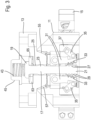
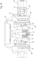
- the locking mechanism is located between a Fig. 4 shown locking position and one shown for example in Fig. 3 shown release position.
- the pivot bolts 31 are pivotally mounted on the locking unit 11.
- an end section of a rigid pivot lever 35 is rotatably mounted on each pivot bolt 31, the other end section of which is rotatably mounted on a coupling ring 37.
- the coupling ring 37 is movable parallel and coaxially to the central axis of the locking bolt 17, but is received radially and circumferentially in a form-fitting manner in a ring receptacle of the locking unit 11, see in particular Fig. 5 .
- the pivot bolts 31 are pivoted about their pivot axis. If the coupling ring 37 is in the upper position, as in Fig. 3 shown, the locking mechanism is in the release position in which the engagement portions 33 of the pivot bolts 31 are not engaged with the locking portion 21 are engaged. However, if the coupling ring 37 is in the lower position, as in Fig. 4 As shown, the locking mechanism is in the locking position, in which the engagement portions 33 of the pivot bolts 31 are engaged with the locking portion 21, so that the pivot bolts 31 lock the locking bolt 17. As Fig. 4 can be removed, in this state the central axes of the pivot levers 35 are oriented orthogonally to the central axis of the locking bolt 17, so that the respective pivot lever 35 blocks an opening movement of the respective pivot bolt 31.
- the head 19 of the locking bolt 17 rests on the preloading mechanism comprising the wedge arrangement 63, 65, by which the locking bolt 17 can be preloaded in the locked position relative to the mounting base 13.
- the wedge arrangement 63, 65 comprises a first wedge 63, which is movable exclusively transversely to the central axis of the locking bolt 17, and a second wedge 65, which is movable exclusively parallel to the central axis of the locking bolt 17.
- both wedges 63, 65 are approximately U-shaped or provided with a recess to pass through the locking bolt 17, wherein in particular the recess of the first wedge 63, which is movable transversely to the central axis of the locking bolt 17, is elongated to enable mobility.
- the pretensioning mechanism can be used to pretension the locking bolt 17 in the release direction, i.e. in the direction away from the locking unit 11, and thus establish a rigid and play-free connection between the payload and the carrier 100, wherein the locking bolt 17 is free from any transverse forces and is only braced in the longitudinal direction, since the head 19 of the locking bolt 17 is only in contact with the second wedge 65 but not with the first wedge 63 (cf. Fig. 7 ).
- a slotted guide 39 in the form of recesses is formed on the two opposite frame parts, which are guided on the locking unit 11.
- the direction of extension of the slotted guide 39 has a component in the direction of movement of the trigger element 15 relative to the locking unit 11 and a component in the direction of movement of the coupling ring 37.
- Engagement elements 41 engage in the slotted guide 39, which are firmly connected to the coupling ring 37 and are connected by means of grooves extending parallel to the direction of movement of the coupling ring 37, but in Fig. 2 through elongated holes in the housing of the locking unit 11, which are covered by the trigger element 15.
- the engagement elements 41 are brought into contact with the Link 39 relative to the engagement elements 41 from the Fig. 2 and 4 shown position into the Fig. 3 shown position.
- the movement of the coupling ring 37 is therefore orthogonal to the movement of the triggering element 15. Due to the movement of the coupling ring 37, the locking mechanism with the pivoting latches 31 is moved from the locking position to the release position. As a result, the mounting base 13 mounted on the payload is released from the locking unit 11 mounted on the carrier 100.
- the direction of extension of the link 39 has a component in the direction of movement of the triggering element 15 relative to the locking unit 11 and a component in the direction of movement of the coupling ring 37.
- the link 39 has starting sections 40 in which the link 39 extends exclusively in the direction of movement of the triggering element 15 relative to the locking unit 11 in order to block any unwanted displacement of the coupling ring 37.
- the release movement of the coupling ring 37 is further supported by a pretensioning device which is Fig. 10 is shown.
- the coupling ring 37 is provided with spring elements designed as compression springs 59, which are pretensioned in the locking position towards the release position and support the coupling ring 37 against a screw bolt 61 screwed to the housing of the locking unit 11.
- release occurs due to a rotation of the synchronizer ring 101 and the mechanically connected release rods 103.
- the release rods 103 are each provided at their end facing each device 10 with a release pin (not shown in the figures), which is guided through an opening 49 provided in a connecting tongue 47 of the release element 15.
- the opening 49 is designed here as an elongated hole, so that a play-affected coupling of the release element 15 to the synchronizer ring 101 is present.
- the release rod 103 and thus the release pin can therefore initially perform an idle stroke. and thereby build up a triggering impulse before the trigger pin hits the material of the connecting tongue 47. This avoids any inhibition caused by friction during the triggering process or can be overcome more easily.
- the release force of the release pin acting on the connecting tongue 47 initiates the displacement of the release element 15, which is additionally supported by compression springs 51, which act on the locking unit 11 on the one hand and on the release element 15 on the other.
- the compression springs 51 are guided around the guide pins 53.
- the mounting bases 13 are provided with cross members 73, the ends of which rest on pre-tensioned release levers 107 before release. Upon release, the release levers 107 relax as shown in Fig. 1 and thereby eject the payload with the mounting bases 13 attached thereto from the carrier 100 in order to release the payload into space.
- a detailed description of the structural design and the exact functioning of such ejection levers 107 is provided in the WO 2021/089167 A1 disclosed, the contents of which are expressly incorporated by reference into the subject matter of the present application.
Landscapes
- Engineering & Computer Science (AREA)
- Remote Sensing (AREA)
- Aviation & Aerospace Engineering (AREA)
- Connection Of Plates (AREA)
- Mutual Connection Of Rods And Tubes (AREA)
- Mounting Components In General For Electric Apparatus (AREA)
Priority Applications (4)
| Application Number | Priority Date | Filing Date | Title |
|---|---|---|---|
| EP23208989.6A EP4552982A1 (fr) | 2023-11-10 | 2023-11-10 | Dispositif de fixation amovible de charge utile à un support et support pour fixer de manière amovible une charge utile |
| PCT/EP2024/081276 WO2025099030A1 (fr) | 2023-11-10 | 2024-11-06 | Dispositif pour fixer de manière amovible une charge utile sur un support, et support de fixation amovible de charge utile |
| AU2024377712A AU2024377712A1 (en) | 2023-11-10 | 2024-11-06 | Device for detachably fastening payload to a carrier, and carrier for detachably fastening payload |
| ARP240103043A AR134374A1 (es) | 2023-11-10 | 2024-11-07 | Dispositivo para la fijación separable de carga útil a un soporte y soporte para la fijación separable de carga útil |
Applications Claiming Priority (1)
| Application Number | Priority Date | Filing Date | Title |
|---|---|---|---|
| EP23208989.6A EP4552982A1 (fr) | 2023-11-10 | 2023-11-10 | Dispositif de fixation amovible de charge utile à un support et support pour fixer de manière amovible une charge utile |
Publications (1)
| Publication Number | Publication Date |
|---|---|
| EP4552982A1 true EP4552982A1 (fr) | 2025-05-14 |
Family
ID=88778750
Family Applications (1)
| Application Number | Title | Priority Date | Filing Date |
|---|---|---|---|
| EP23208989.6A Pending EP4552982A1 (fr) | 2023-11-10 | 2023-11-10 | Dispositif de fixation amovible de charge utile à un support et support pour fixer de manière amovible une charge utile |
Country Status (4)
| Country | Link |
|---|---|
| EP (1) | EP4552982A1 (fr) |
| AR (1) | AR134374A1 (fr) |
| AU (1) | AU2024377712A1 (fr) |
| WO (1) | WO2025099030A1 (fr) |
Citations (5)
| Publication number | Priority date | Publication date | Assignee | Title |
|---|---|---|---|---|
| US4682804A (en) * | 1984-04-23 | 1987-07-28 | Trw Inc. | Releasable coupling assembly |
| US5123794A (en) * | 1990-04-25 | 1992-06-23 | Aerospatiale Societe Nationale Industrielle | Connecting mechanism which can be rapidly unlocked and usable on space vehicles |
| US20210123465A1 (en) * | 2020-03-30 | 2021-04-29 | Harbin Institute Of Technology | Connection and Separation Device Driven by Memory Alloy Wires |
| WO2021089167A1 (fr) | 2019-11-07 | 2021-05-14 | Exolaunch Gmbh | Système de séparation pour satellite |
| US20210339891A1 (en) * | 2018-10-19 | 2021-11-04 | Ruag Space Ab | Separation device for a spacecraft |
-
2023
- 2023-11-10 EP EP23208989.6A patent/EP4552982A1/fr active Pending
-
2024
- 2024-11-06 WO PCT/EP2024/081276 patent/WO2025099030A1/fr active Pending
- 2024-11-06 AU AU2024377712A patent/AU2024377712A1/en active Pending
- 2024-11-07 AR ARP240103043A patent/AR134374A1/es unknown
Patent Citations (5)
| Publication number | Priority date | Publication date | Assignee | Title |
|---|---|---|---|---|
| US4682804A (en) * | 1984-04-23 | 1987-07-28 | Trw Inc. | Releasable coupling assembly |
| US5123794A (en) * | 1990-04-25 | 1992-06-23 | Aerospatiale Societe Nationale Industrielle | Connecting mechanism which can be rapidly unlocked and usable on space vehicles |
| US20210339891A1 (en) * | 2018-10-19 | 2021-11-04 | Ruag Space Ab | Separation device for a spacecraft |
| WO2021089167A1 (fr) | 2019-11-07 | 2021-05-14 | Exolaunch Gmbh | Système de séparation pour satellite |
| US20210123465A1 (en) * | 2020-03-30 | 2021-04-29 | Harbin Institute Of Technology | Connection and Separation Device Driven by Memory Alloy Wires |
Also Published As
| Publication number | Publication date |
|---|---|
| AU2024377712A1 (en) | 2026-05-14 |
| AR134374A1 (es) | 2026-01-14 |
| WO2025099030A1 (fr) | 2025-05-15 |
Similar Documents
| Publication | Publication Date | Title |
|---|---|---|
| DE4439644C2 (de) | Verriegelungssystem für Beschläge von Fahrzeugsitzen mit freischwenkbarer Rückenlehne | |
| EP2713061B1 (fr) | Fermeture et système d'habillage pour celle-ci | |
| EP4290038B1 (fr) | Charnière destinée à relier de manière amovible et pivotante une aile à une partie de base | |
| EP3021974A1 (fr) | Centrifugeuse | |
| EP1984590B1 (fr) | Dispositif de fixation serrable | |
| EP2683577B1 (fr) | Dispositif de déverrouillage | |
| DE102015014368A1 (de) | Klappflügel für einen Flugkörper sowie einen Flugkörper mit mindestens einem daran angeordneten Klappflügel | |
| DE10033093B4 (de) | Vorrichtung zum lösbaren verbinden rotationssystemmetrischer Bauteile | |
| EP1809441B1 (fr) | Dispositif de serrage et de prehension, en particulier pince lineaire ou centrale | |
| DE69722026T2 (de) | Endstück einer hülle für einen bowdenzug | |
| EP3807012B1 (fr) | Centrifugeuse | |
| EP4200532B1 (fr) | Dispositif tendeur pour tendre des moyens de tension tels que des chaînes, des sangles, des cordes ou similaires | |
| WO2025099030A1 (fr) | Dispositif pour fixer de manière amovible une charge utile sur un support, et support de fixation amovible de charge utile | |
| DE102019102768B4 (de) | Drehverschluss | |
| DE102018123734B4 (de) | Vorrichtung, System und Verfahren zum Sichern einer Last in einem Fahrzeug | |
| DE4109902C2 (fr) | ||
| EP1888280A1 (fr) | Liaison entre deux parties d'outil | |
| EP2577072B1 (fr) | Ensemble de fixation | |
| DE3205133C2 (fr) | ||
| DE102022114784B3 (de) | Fitting und System aufweisend ein Fitting und eine Schiene | |
| EP4242115B1 (fr) | Unité d'éjection | |
| EP1932719A1 (fr) | Dispositif de retenue pour tronçons de bagages | |
| EP3868636A1 (fr) | Trottinette | |
| EP3795269A1 (fr) | Dispositif de fixation permettant de fixer un outil d'usinage à une machine-outil, agencement d'outils, chargeur d'outils et procédé de fonctionnement d'une machine-outil | |
| EP1522357B1 (fr) | Dispositif de fermeture pour des électrodes |
Legal Events
| Date | Code | Title | Description |
|---|---|---|---|
| PUAI | Public reference made under article 153(3) epc to a published international application that has entered the european phase |
Free format text: ORIGINAL CODE: 0009012 |
|
| STAA | Information on the status of an ep patent application or granted ep patent |
Free format text: STATUS: THE APPLICATION HAS BEEN PUBLISHED |
|
| AK | Designated contracting states |
Kind code of ref document: A1 Designated state(s): AL AT BE BG CH CY CZ DE DK EE ES FI FR GB GR HR HU IE IS IT LI LT LU LV MC ME MK MT NL NO PL PT RO RS SE SI SK SM TR |
|
| STAA | Information on the status of an ep patent application or granted ep patent |
Free format text: STATUS: REQUEST FOR EXAMINATION WAS MADE |
|
| 17P | Request for examination filed |
Effective date: 20251110 |